|
|
|
Recent progress on excitation and manipulation of spin-waves in spin Hall nano-oscillators |
| Liyuan Li(李丽媛)1, Lina Chen(陈丽娜)1,2, †, Ronghua Liu(刘荣华)1,, ‡, and Youwei Du(都有为)1 |
1 National Laboratory of Solid State Microstructures, School of Physics and Collaborative Innovation Center of Advanced Microstructures, Nanjing University, Nanjing 210093, China
2 New Energy Technology Engineering Laboratory of Jiangsu Provence & School of Science, Nanjing University of Posts and Telecommunications, Nanjing 210023, China |
|
|
|
|
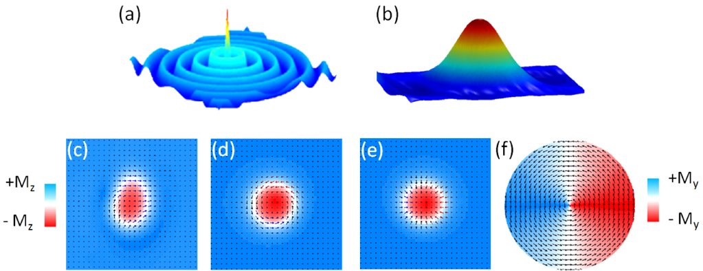
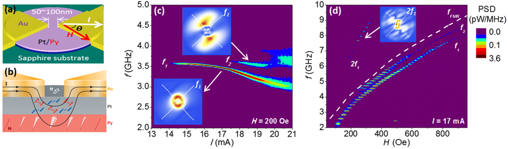
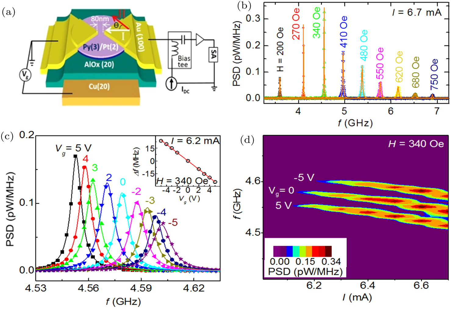
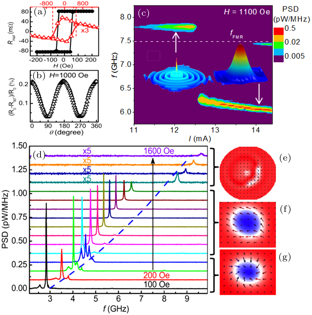
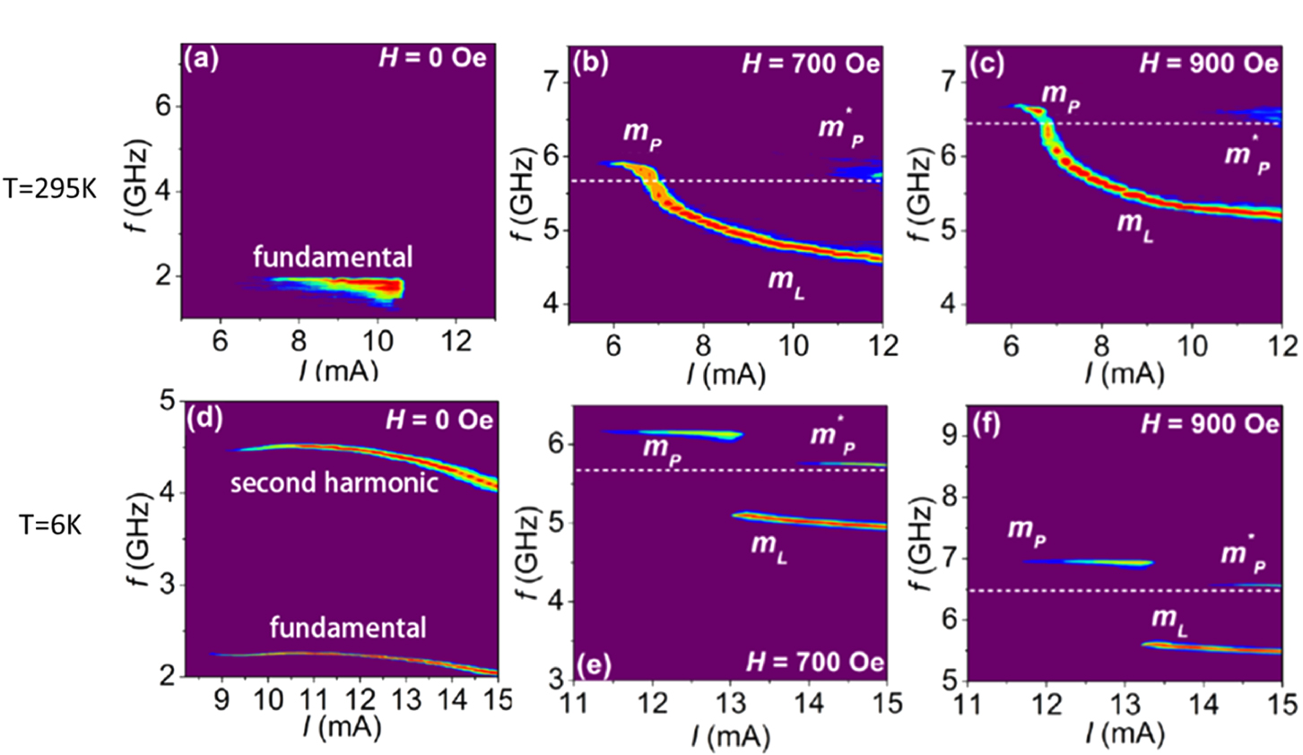
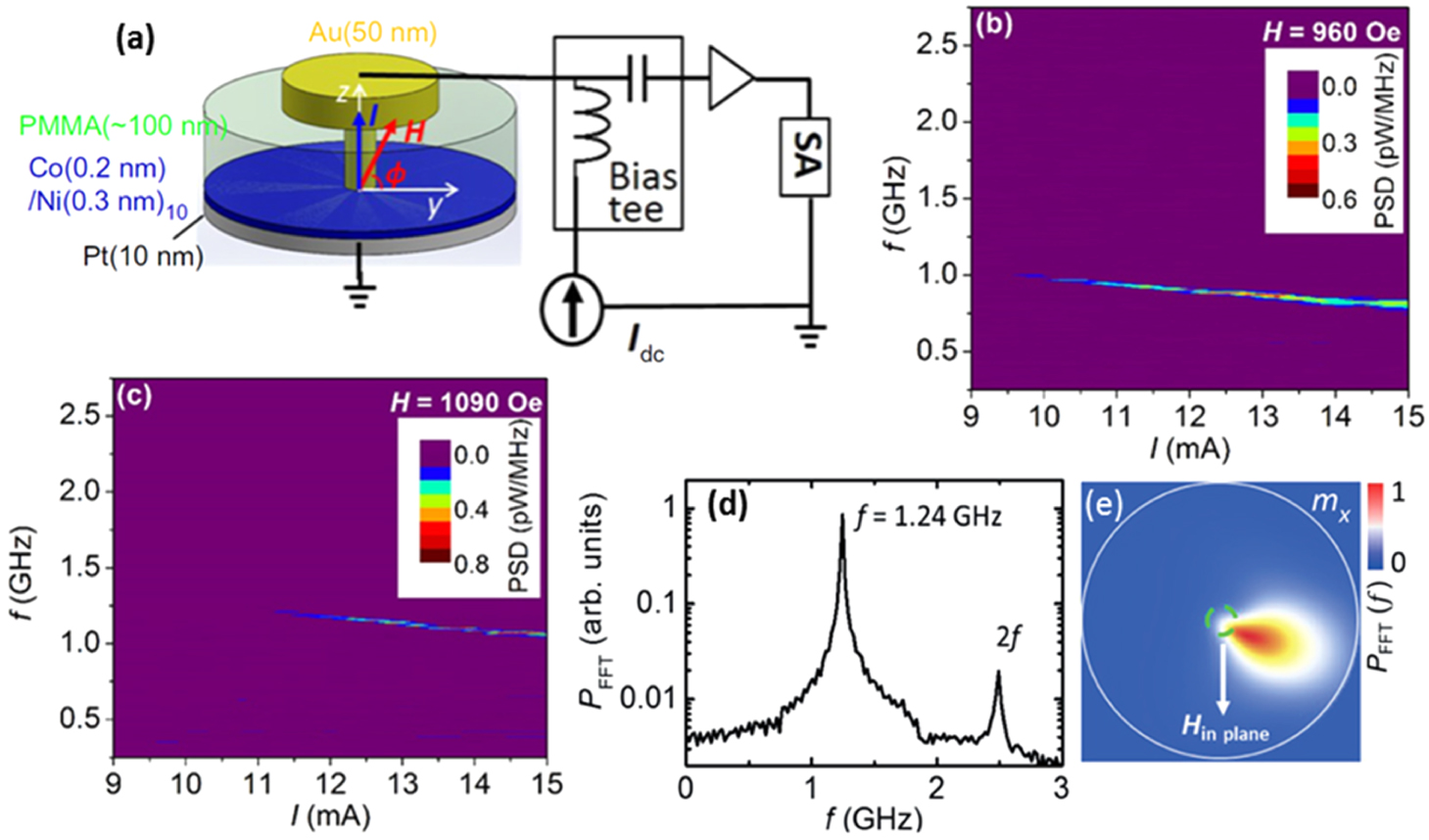
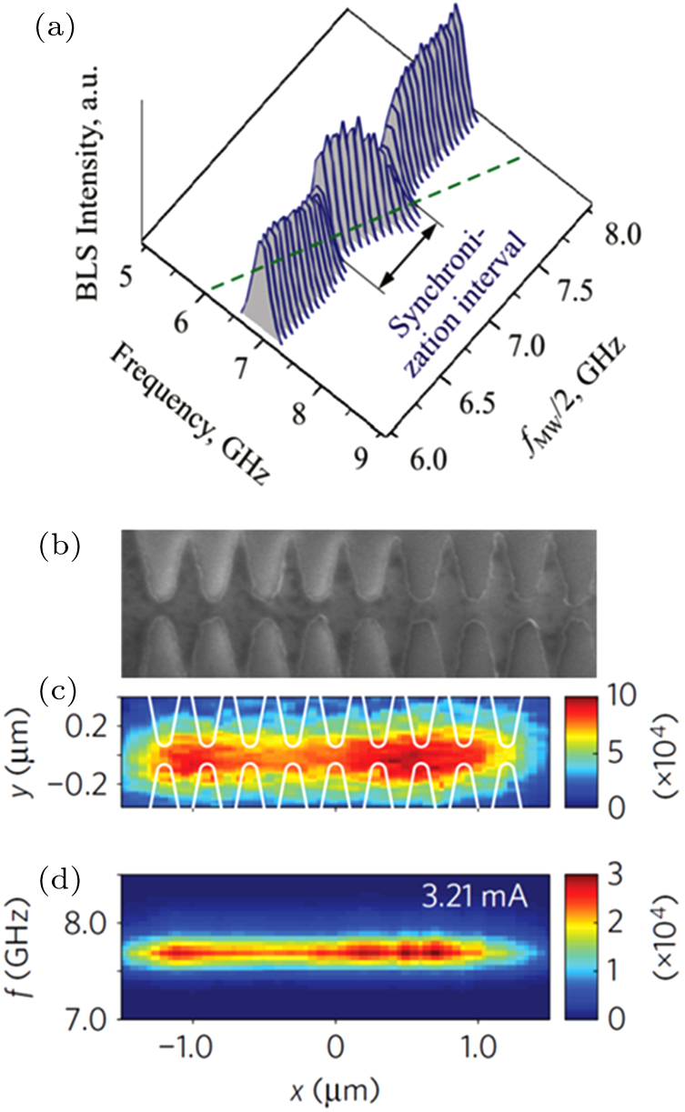
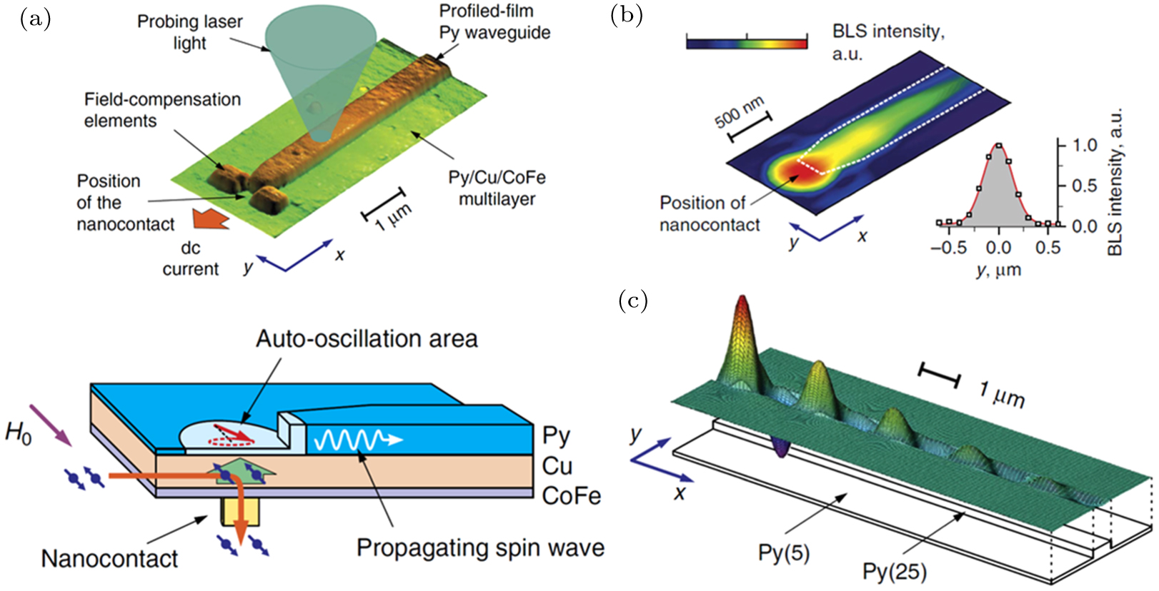
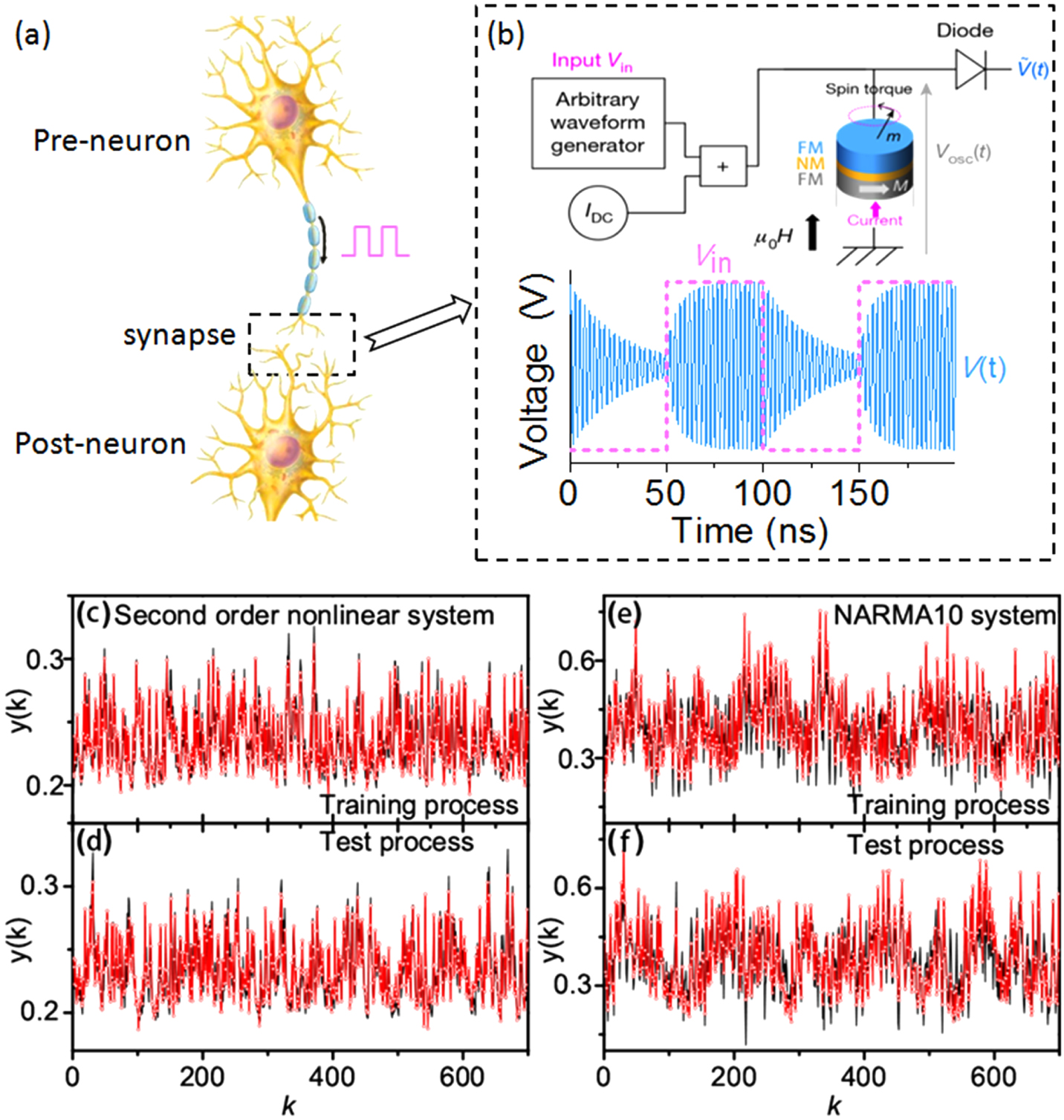
Abstract Spin Hall nano oscillator (SHNO), a new type spintronic nano-device, can electrically excite and control spin waves in both nanoscale magnetic metals and insulators with low damping by the spin current due to spin Hall effect and interfacial Rashba effect. Several spin-wave modes have been excited successfully and investigated substantially in SHNOs based on dozens of different ferromagnetic/nonmagnetic (FM/NM) bilayer systems (e.g., FM = Py, [Co/Ni], Fe, CoFeB, Y3Fe5O12; NM = Pt, Ta, W). Here, we will review recent progress about spin-wave excitation and experimental parameters dependent dynamics in SHNOs. The nanogap SHNOs with in-plane magnetization exhibit a nonlinear self-localized bullet soliton localized at the center of the gap between the electrodes and a secondary high-frequency mode which coexists with the primary bullet mode at higher currents. While in the nanogap SHNOs with out of plane magnetization, besides both nonlinear bullet soliton and propagating spin-wave mode are achieved and controlled by varying the external magnetic field and current, the magnetic bubble skyrmion mode also can be excited at a low in-plane magnetic field. These spin-wave modes show thermal-induced mode hopping behavior at high temperature due to the coupling between the modes mediated by thermal magnon mediated scattering. Moreover, thanks to the perpendicular magnetic anisotropy induced effective field, the single coherent mode also can be achieved without applying an external magnetic field. The strong nonlinear effect of spin waves makes SHNOs easy to achieve synchronization with external microwave signals or mutual synchronization between multiple oscillators which improve the coherence and power of oscillation modes significantly. Spin waves in SHNOs with an external free magnetic layer have a wide range of applications from as a nanoscale signal source of low power consumption magnonic devices to spin-based neuromorphic computing systems in the field of artificial intelligence.
|
Received: 03 July 2020
Revised: 07 August 2020
Accepted manuscript online: 13 August 2020
|
| Fund: the National Key Research and Development Program of China (Grant No. 2016YFA0300803), the National Natural Science Foundation of China (Grant Nos. 11774150, 12074178, and 12004171), the Applied Basic Research Programs of Science and Technology Commission Foundation of Jiangsu Province, China (Grant No. BK20170627), and the Open Research Fund of Jiangsu Provincial Key Laboratory for Nanotechnology. |
|
Corresponding Authors:
†Corresponding author. E-mail: linachen@nju.edu.cn ‡Corresponding author. E-mail: rhliu@nju.edu.cn
|
Cite this article:
Liyuan Li(李丽媛), Lina Chen(陈丽娜), Ronghua Liu(刘荣华), and Youwei Du(都有为) Recent progress on excitation and manipulation of spin-waves in spin Hall nano-oscillators 2020 Chin. Phys. B 29 117102
|
| [1] |
|
| [2] |
|
| [3] |
Liu H, Bedau D, Backes D, Katine J A, Langer J, Kent A D 2010 Appl. Phys. Lett. 97 242510 DOI: 10.1063/1.3527962 |
| [4] |
Choi G M, Moon C H, Min B C, Lee K J, Cahill D G 2015 Nat. Phys. 11 576 DOI: 10.1038/nphys3355 |
| [5] |
|
| [6] |
Chumak A V, Vasyuchka V I, Serga A A, Hillebrands B 2015 Nat. Phys. 11 453 DOI: 10.1038/nphys3347 |
| [7] |
|
| [8] |
Uchida K, Takahashi S, Harii K, Ieda J, Koshibae W, Ando K, Maekawa S, Saitoh E 2008 Nature 455 778 DOI: 10.1038/nature07321 |
| [9] |
Jungwirth T, Wunderlich J, Olejnik K 2012 Nat. Mater. 11 382 DOI: 10.1038/nmat3279 |
| [10] |
|
| [11] |
Chernyshov A, Overby M, Liu X Y, Furdyna J K, Lyanda-Geller Y, Rokhinson L P 2009 Nat. Phys. 5 656 DOI: 10.1038/nphys1362 |
| [12] |
|
| [13] |
|
| [14] |
Feng X Y, Zhang Q H, Zhang H W, Zhang Y, Zhong R, Lu B W, Cao J W, Fan X L 2019 Chin. Phys. B 28 107105 DOI: 10.1088/1674-1056/ab425e |
| [15] |
|
| [16] |
|
| [17] |
|
| [18] |
|
| [19] |
Pi U H, Kim K W, Bae J Y, Lee S C, Cho Y J, Kim K S, Seo S 2010 Appl. Phys. Lett. 97 162507 DOI: 10.1063/1.3502596 |
| [20] |
|
| [21] |
|
| [22] |
|
| [23] |
Madami M, Bonetti S, Consolo G, Tacchi S, Carlotti G, Gubbiotti G, Mancoff F B, Yar M A, Akerman J 2011 Nat. Nanotechnol. 6 635 DOI: 10.1038/nnano.2011.140 |
| [24] |
Dumas R K, Iacocca E, Bonetti S, Sani S R, Mohseni S M, Eklund A, Persson J, Heinonen O, Akerman J 2013 Phys. Rev. Lett. 110 257202 DOI: 10.1103/PhysRevLett.110.257202 |
| [25] |
|
| [26] |
|
| [27] |
Bonetti S, Tiberkevich V, Consolo G, Finocchio G, Muduli P, Mancoff F, Slavin A, Akerman J 2010 Phys. Rev. Lett. 105 217204 DOI: 10.1103/PhysRevLett.95.237201 |
| [28] |
|
| [29] |
|
| [30] |
|
| [31] |
|
| [32] |
|
| [33] |
Mohseni S M, Sani S R, Persson J, Nguyen T N A, Chung S, Pogoryelov Y, Muduli P K, Iacocca E, Eklund A, Dumas R K, Bonetti S, Deac A, Hoefer M A, Akerman J 2013 Science 339 1295 DOI: 10.1038/nmat3459 |
| [34] |
Demidov V E, Urazhdin S, Ulrichs H, Tiberkevich V, Slavin A, Baither D, Schmitz G, Demokritov S O 2012 Nat. Mater. 11 1028 DOI: 10.7498/aps.67.20180906 |
| [35] |
|
| [36] |
|
| [37] |
|
| [38] |
|
| [39] |
Nakamura K, Shimabukuro R, Fujiwara Y, Akiyama T, Ito T, Freeman A J 2009 Phys. Rev. Lett. 102 187201 DOI: 10.1038/nnano.2008.406 |
| [40] |
Maruyama T, Shiota Y, Nozaki T, Ohta K, Toda N, Mizuguchi M, Tulapurkar A A, Shinjo T, Shiraishi M, Mizukami S, Ando Y, Suzuki Y 2009 Nat. Nanotechnol. 4 158 DOI: 10.1038/nmat3130 |
| [41] |
Chiba D, Fukami S, Shimamura K, Ishiwata N, Kobayashi K, Ono T 2011 Nat. Mater. 10 853 DOI: 10.1038/nmat3171 |
| [42] |
|
| [43] |
|
| [44] |
Zheng Z Y, Zhang Y, Zhu D Q, Zhang K, Feng X Q, He Y, Chen L, Zhang Z Z, Liu D J, Zhang Y G, Amiri P K, Zhao W S 2020 Chin. Phys. B 29 078505 DOI: 10.1103/PhysRevLett.68.682 |
| [45] |
|
| [46] |
Mcguire T R, Potter R I 1975 IEEE Transactions on Magnetics 11 1018 DOI: 10.1063/1.3680091 |
| [47] |
Bortolotti P, Dussaux A, Grollier J, Cros V, Fukushima A, Kubota H, Yakushiji K, Yuasa S, Ando K, Fert A 2012 Appl. Phys. Lett. 100 042408 DOI: 10.1063/1.4896634 |
| [48] |
|
| [49] |
|
| [50] |
|
| [51] |
Chen L N, Urazhdin S, Zhou K Y, Du Y W, Liu R H 2020 Phys. Rev. Appl. 13 024034 DOI: 10.1038/ncomms4179 |
| [52] |
Demidov V E, Ulrichs H, Gurevich S V, Demokritov S O, Tiberkevich V S, Slavin A N, Zholud A, Urazhdin S 2014 Nat. Commun. 5 3179 DOI: 10.1038/nphys3927 |
| [53] |
Awad A A, Dürrenfeld P, Houshang A, Dvornik M, Iacocca E, Dumas R K, Åkerman J 2016 Nat. Phys. 13 292 DOI: 10.1038/ncomms15825 |
| [54] |
Lebrun R, Tsunegi S, Bortolotti P, Kubota H, Jenkins A S, Romera M, Yakushiji K, Fukushima A, Grollier J, Yuasa S, Cros V 2017 Nat. Commun. 8 15825 DOI: 10.1063/1.5115183 |
| [55] |
Jiang W C, Chen L N, Zhou K Y, Li L Y, Fu Q W, Du Y W, Liu R H 2019 Appl. Phys. Lett. 115 192403 DOI: 10.1038/srep44772 |
| [56] |
Vodenicarevic D, Locatelli N, Araujo F A, Grollier J, Querlioz D 2017 Scientific Reports 7 44772 DOI: 10.1063/1.4901027 |
| [57] |
Demidov V E, Urazhdin S, Zholud A, Sadovnikov A V, Demokritov S O 2014 Appl. Phys. Lett. 105 172410 DOI: 10.1038/ncomms10446 |
| [58] |
Demidov V E, Urazhdin S, Liu R, Divinskiy B, Telegin A, Demokritov S O 2016 Nat. Commun. 7 10446 DOI: 10.1109/TMAG.2014.2388196 |
| [59] |
|
| [60] |
Zhang Y J, Zheng Q, Zhu X R, Yuan Z, Xia K 2020 Science China-Phys. Mechanics & Astronomy 63 277531 DOI: 10.1063/1.5143382 |
| [61] |
Zheng Q, Zhu X R, Mi Y Y, Yuan Z, Xia K 2020 Aip Adv. 10 025116 DOI: 10.1063/5.0001557 |
| [62] |
|
| [63] |
Furuta T, Fujii K, Nakajima K, Tsunegi S, Kubota H, Suzuki Y, Miwa S 2018 Phys. Rev. Appl. 10 034063 DOI: 10.1126/science.1091277 |
| [64] |
|
| [65] |
|
| [66] |
|
| [67] |
Torrejon J, Riou M, Araujo F A, Tsunegi S, Khalsa G, Querlioz D, Bortolotti P, Cros V, Yakushiji K, Fukushima A, Kubota H, Uasa S Y, Stiles M D, Grollier J 2017 Nature 547 428 DOI: 10.1038/s41467-017-02337-y |
| [68] |
|
| [69] |
Romera M, Talatchian P, Tsunegi S, Araujo F A, Cros V, Bortolotti P, Trastoy J, Yakushiji K, Fukushima A, Kubota H, Yuasa S, Ernoult M, Vodenicarevic D, Hirtzlin T, Locatelli N, Querlioz D, Grollier J 2018 Nature 563 230 DOI: 10.1038/s41565-019-0593-9 |
| [70] |
Zahedinejad M, Awad A A, Muralidhar S, Khymyn R, Fulara H, Mazraati H, Dvornik M, Akerman J 2020 Nat. Nanotechnol. 15 47 DOI: 10.1038/s41928-019-0360-9 |
| [71] |
|
| [72] |
Cai J L, Fang B, Zhang L K, Lv W X, Zhang B S, Zhou T J, Finocchio G, Zeng Z M 2019 Phys. Rev. Appl. 11 034015 DOI: 10.1063/1.5055860 |
| [73] |
Camsari K Y, Sutton B M, Datta S 2019 Appl. Phys. Rev. 6 011305 DOI: 10.1063/1.5055860 |
| [74] |
Zhang S, Luo S J, Xu N, Zou Q M, Song M, Yun J J, Luo Q, Guo Z, Li R F, Tian W C, Li X, Zhou H G, Chen H M, Zhang Y, Yang X F, Jiang W J, Shen K, Hong J M, Yuan Z, Xi L, Xia K, Salahuddin S, Dieny B, You L 2019 Adv. Electron. Mater. 5 1800782 DOI: 10.1002/aelm.201800782 |
| No Suggested Reading articles found! |
|
|
Viewed |
|
|
|
Full text
|
|
|
|
|
Abstract
|
|
|
|
|
Cited |
|
|
|
|
Altmetric
|
|
blogs
Facebook pages
Wikipedia page
Google+ users
|
Online attention
Altmetric calculates a score based on the online attention an article receives. Each coloured thread in the circle represents a different type of online attention. The number in the centre is the Altmetric score. Social media and mainstream news media are the main sources that calculate the score. Reference managers such as Mendeley are also tracked but do not contribute to the score. Older articles often score higher because they have had more time to get noticed. To account for this, Altmetric has included the context data for other articles of a similar age.
View more on Altmetrics
|
|
|