| CONDENSED MATTER: STRUCTURAL, MECHANICAL, AND THERMAL PROPERTIES |
Prev
Next
|
|
|
Plastic deformation mechanism transition of Ti/Ni nanolaminate with pre-existing crack: Molecular dynamics study |
| Meng-Jia Su(宿梦嘉)1, 2, Qiong Deng(邓琼)1, 2, †, Min-Rong An(安敏荣)3,, ‡, and Lan-Ting Liu(刘兰亭)1, 2 |
1 Fundamental Science on Aircraft Structural Mechanics and Strength Laboratory, Northwestern Polytechnical University, Xi’an 710072, China
2 School of Aeronautics, Northwestern Polytechnical University, Xi’an 710072, China
3 College of Materials Science and Engineering, Xi’an Shiyou University, Xi’an 710065, China |
|
|
|
|
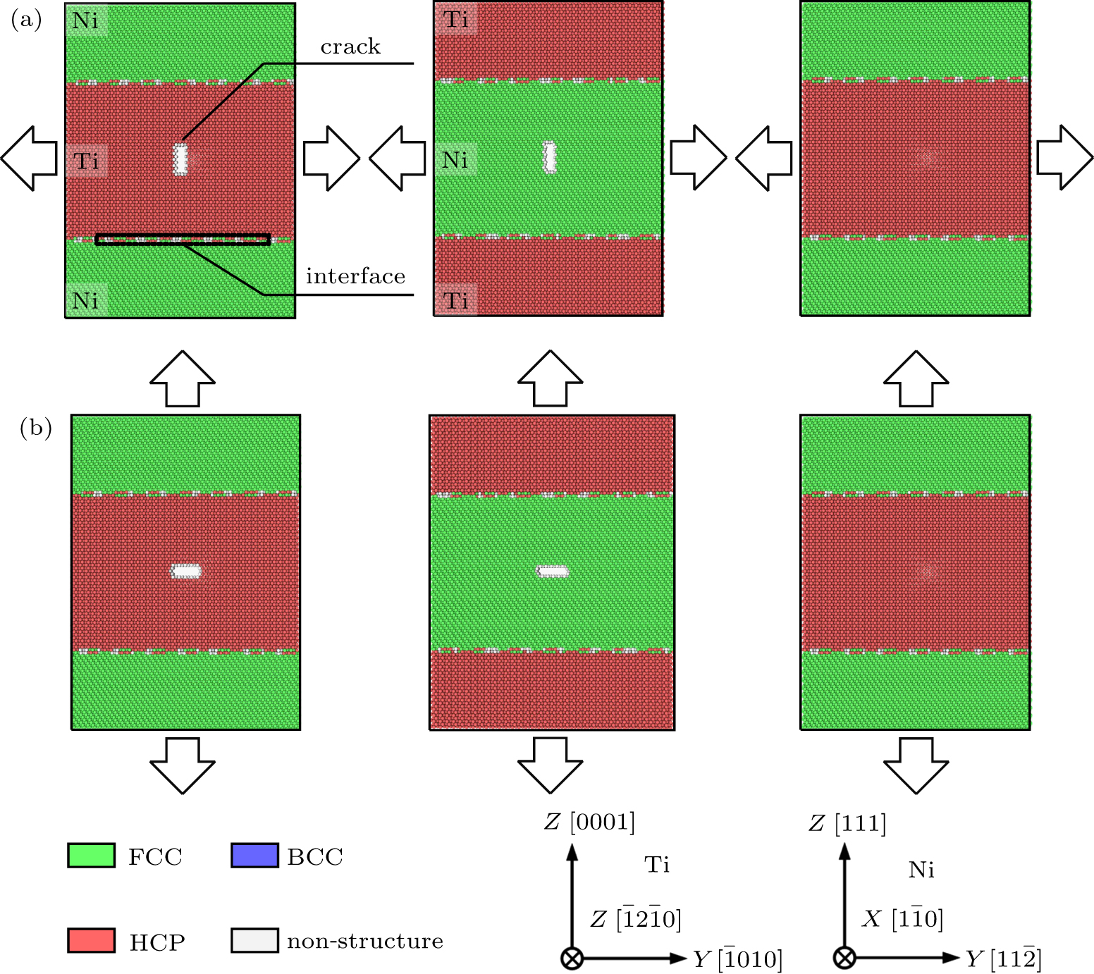
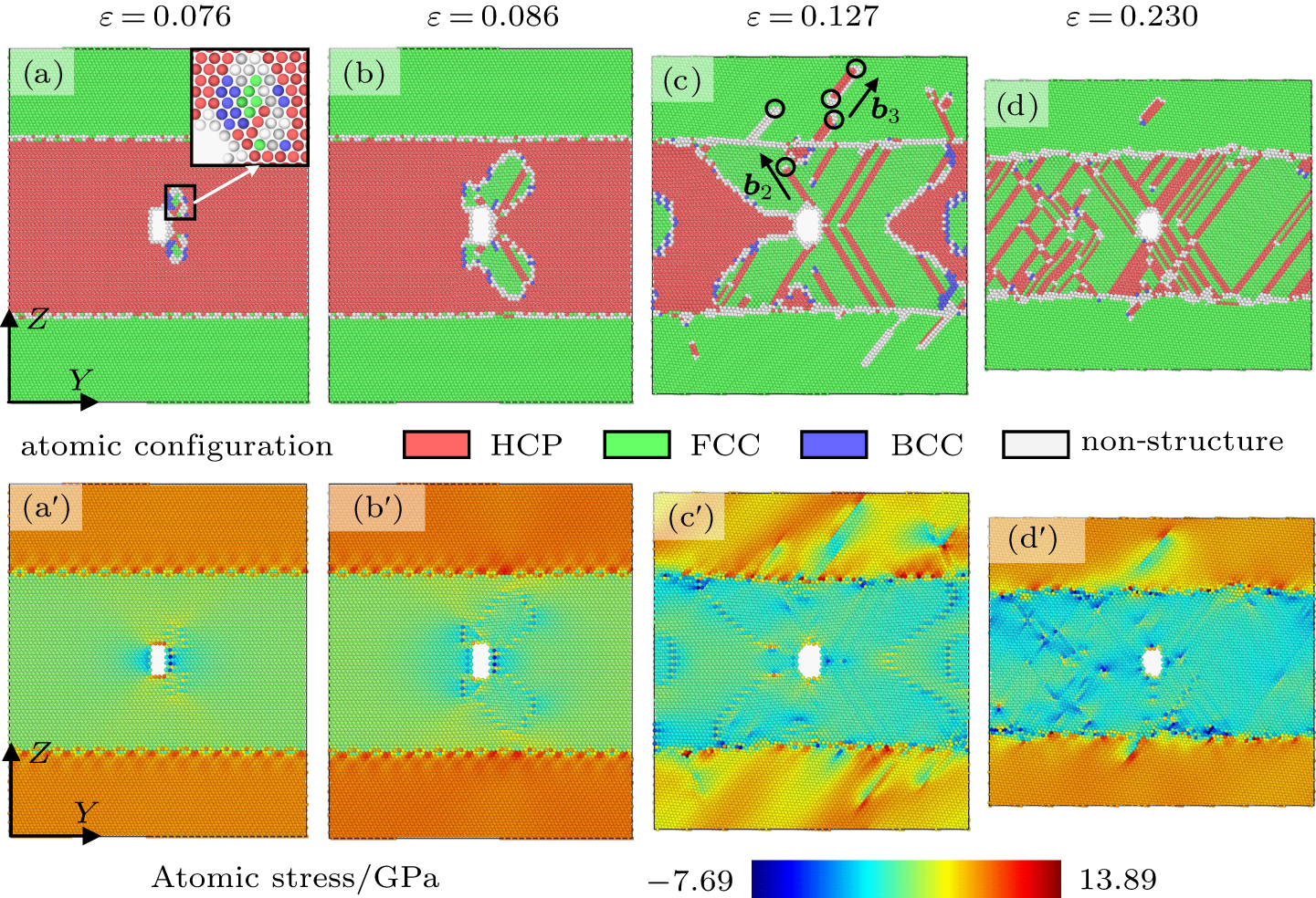
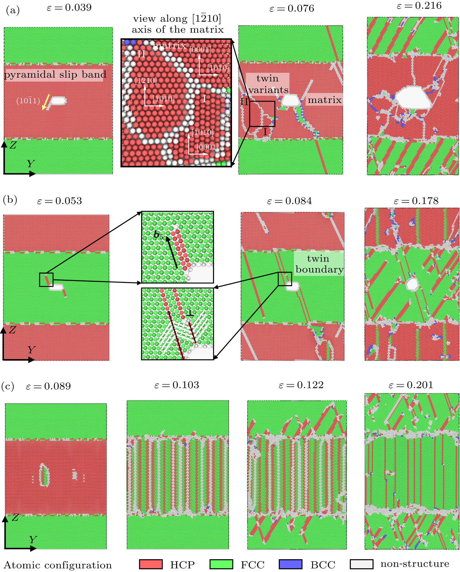
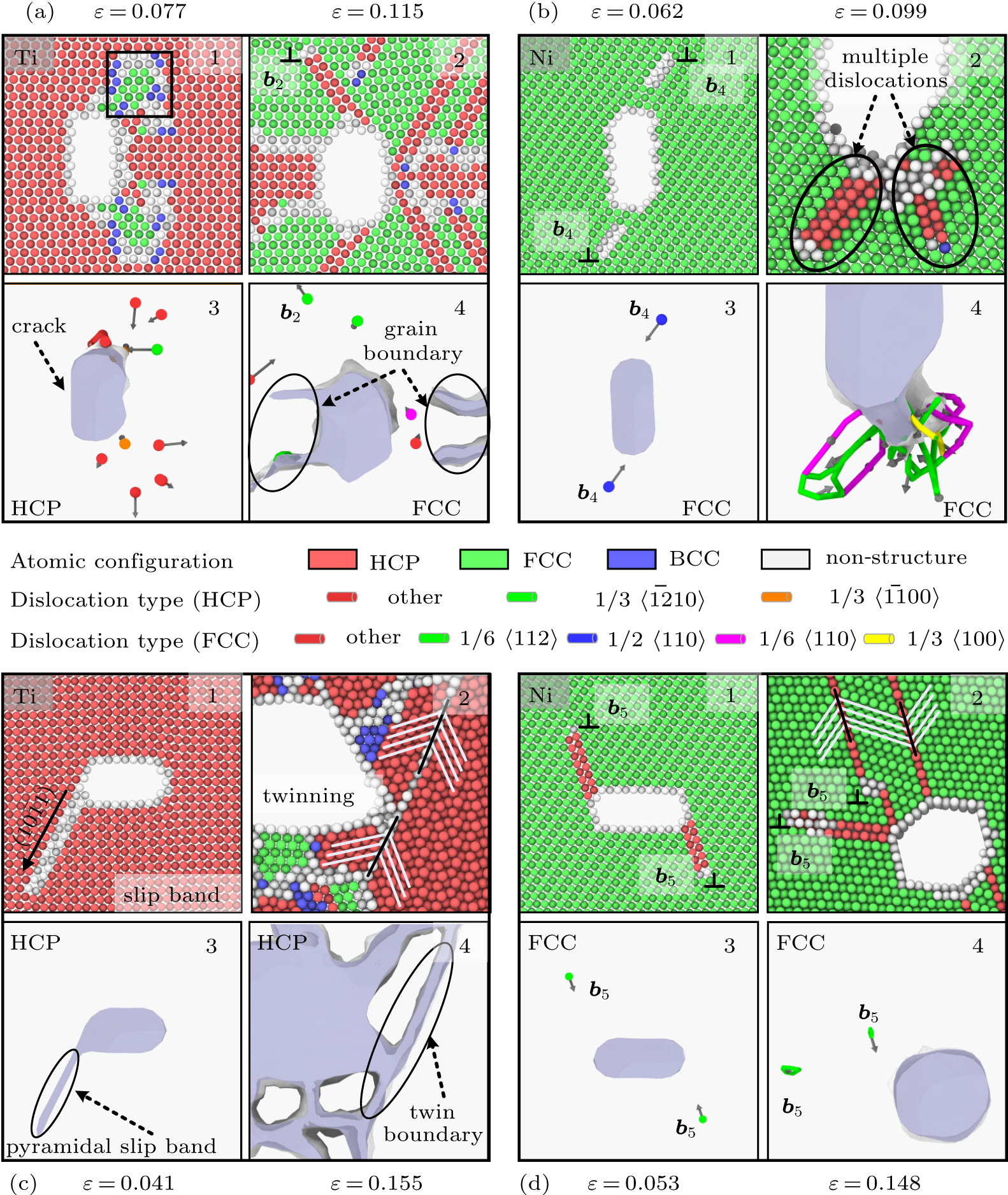
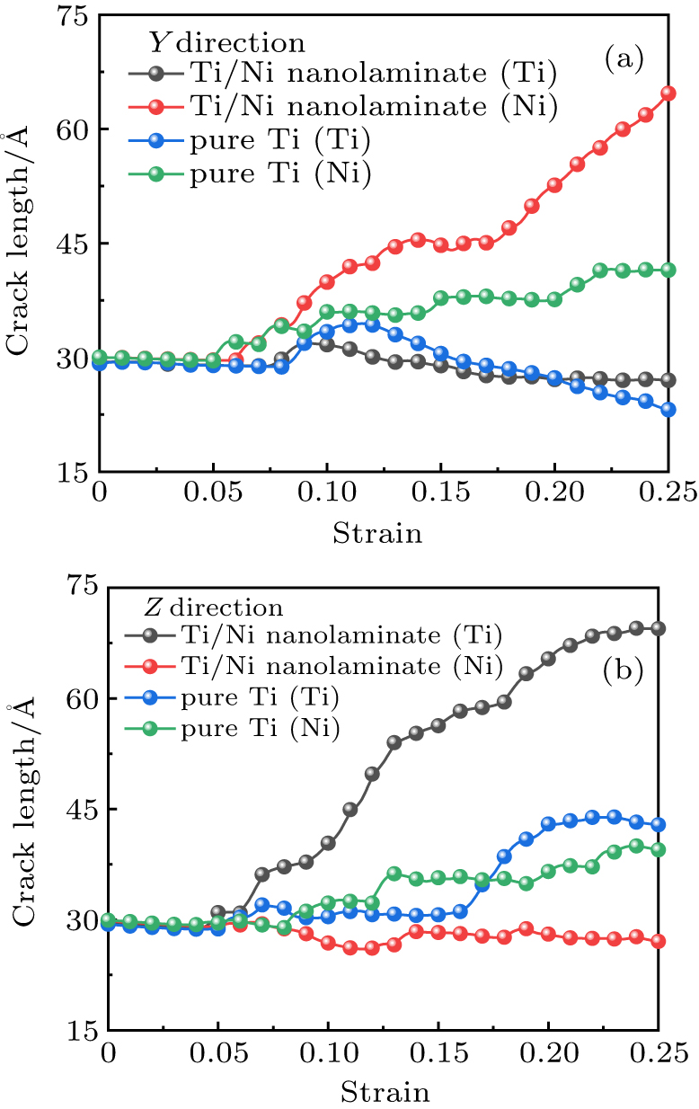
Abstract Tensile behaviors of Ti/Ni nanolaminate with model-I crack are investigated by molecular dynamics simulations. The Ti/Ni nanolaminates with center crack either in Ti layer or in Ni layer under different loading directions are utilized to systematically study the mechanical performance of the cracked material. The results indicate that pre-existing crack dramatically changes the plastic deformation mechanism of the Ti/Ni nanolaminate. Unlike the initial plastic deformation originating from the interface or weak Ti layer of the crack-free samples, the plastic behavior of cracked Ti/Ni nanolaminate first occurs at the crack tip due to the local stress concentration. Subsequent plastic deformation is dominated by the interaction between the crack and interface. The Ti/Ni interface not only impedes the movement of the initial plastic deformation carriers (dislocation, slip band, and deformation twinning) from the crack tip, but also promotes the movement of interfacial dislocations in the tension process. Microstructure evolution analysis further confirms that the plastic deformation mechanism transition is ascribed to the orientation-dependent tensile behavior at the crack tip, which is intrinsically attributed to the anisotropy of the certain crystal structure and loading direction of the cracked Ti/Ni nanolaminate. In addition, by analyzing the effects of different plastic deformation carriers on crack propagation in specific crystal, it can be discovered that the interfacial dislocations moving towards the crack tip can further promote the crack growth.
|
Received: 08 May 2020
Revised: 13 June 2020
Accepted manuscript online: 06 July 2020
|
| Fund: the National Natural Science Foundation of China (Grant No. 11572259), the Program for International Cooperation and Exchanges of Shaanxi Province, China (Grant No. 2016KW-049), the Natural Science Foundation of Shaanxi Province, China (Grant No. 2019JQ-827), and the Scientific Research Program Funded by Shaanxi Provincial Education Department, China (Grant No. 19JK0672). |
|
Corresponding Authors:
†Corresponding author. E-mail: dengqiong24@nwpu.edu.cn ‡Corresponding author. E-mail: amr_lr@126.com
|
Cite this article:
Meng-Jia Su(宿梦嘉), Qiong Deng(邓琼)†, Min-Rong An(安敏荣), and Lan-Ting Liu(刘兰亭) Plastic deformation mechanism transition of Ti/Ni nanolaminate with pre-existing crack: Molecular dynamics study 2020 Chin. Phys. B 29 116201
|
| [1] |
|
| [2] |
Veres T, Cser L, Bodnarchuck V, Ignatovich V, Horvath Z E, Nagy B 2013 Thin Solid Films 540 69 DOI: 10.1016/j.tsf.2013.06.001 |
| [3] |
|
| [4] |
|
| [5] |
|
| [6] |
|
| [7] |
|
| [8] |
|
| [9] |
|
| [10] |
|
| [11] |
|
| [12] |
|
| [13] |
|
| [14] |
Li R, Liu T, Chen X, Chen S C, Fu Y H, Liu L 2018 Acta Phys. Sin. 67 190202 in Chinese DOI: 10.7498/aps.67.20180958 |
| [15] |
|
| [16] |
|
| [17] |
|
| [18] |
|
| [19] |
|
| [20] |
|
| [21] |
|
| [22] |
|
| [23] |
|
| [24] |
An M R, Song H Y, Deng Q, Su M J, Liu M Y 2019 J. Appl. Phys. 125 165307 DOI: 10.1063/1.5085455 |
| [25] |
|
| [26] |
|
| [27] |
|
| [28] |
|
| [29] |
Zhou X W, Wadley H N G, Johnson R A, Larson D J, Tabat N, Cerezo A, Petford-long A K, Smith G D W, Clifton P H, Martens R L, Kelly T F 2001 Acta Mater. 49 4005 DOI: 10.1016/S1359-6454(01)00287-7 |
| [30] |
|
| [31] |
|
| [32] |
|
| [33] |
|
| [34] |
|
| [35] |
|
| [36] |
|
| [37] |
|
| [38] |
|
| [39] |
|
| [40] |
|
| [41] |
|
| [42] |
|
| [43] |
|
| [44] |
|
| [45] |
|
| [46] |
Yamakov V I, Warner D H, Zamora R J, Saether E, Curtin W A, Glaessgen E H 2014 J. Mech. Phys. Solids 65 35 DOI: 10.1016/j.jmps.2013.12.009 |
| [47] |
|
| No Suggested Reading articles found! |
|
|
Viewed |
|
|
|
Full text
|
|
|
|
|
Abstract
|
|
|
|
|
Cited |
|
|
|
|
Altmetric
|
|
blogs
Facebook pages
Wikipedia page
Google+ users
|
Online attention
Altmetric calculates a score based on the online attention an article receives. Each coloured thread in the circle represents a different type of online attention. The number in the centre is the Altmetric score. Social media and mainstream news media are the main sources that calculate the score. Reference managers such as Mendeley are also tracked but do not contribute to the score. Older articles often score higher because they have had more time to get noticed. To account for this, Altmetric has included the context data for other articles of a similar age.
View more on Altmetrics
|
|
|