|
|
|
Nonlinear dynamics in non-volatile locally-active memristor for periodic and chaotic oscillations |
| Wen-Yu Gu(谷文玉), Guang-Yi Wang(王光义)†, Yu-Jiao Dong(董玉姣), and Jia-Jie Ying(应佳捷) |
| Institute of Modern Circuits and Intelligent Information, Hangzhou Dianzi University, Hangzhou 310018, China |
|
|
|
|
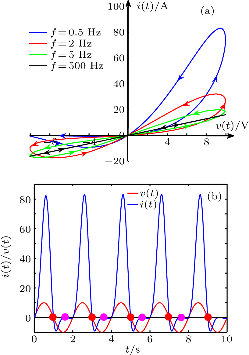
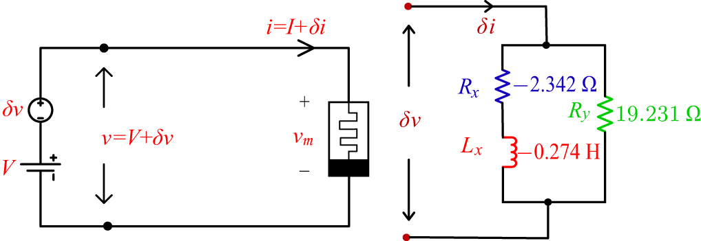
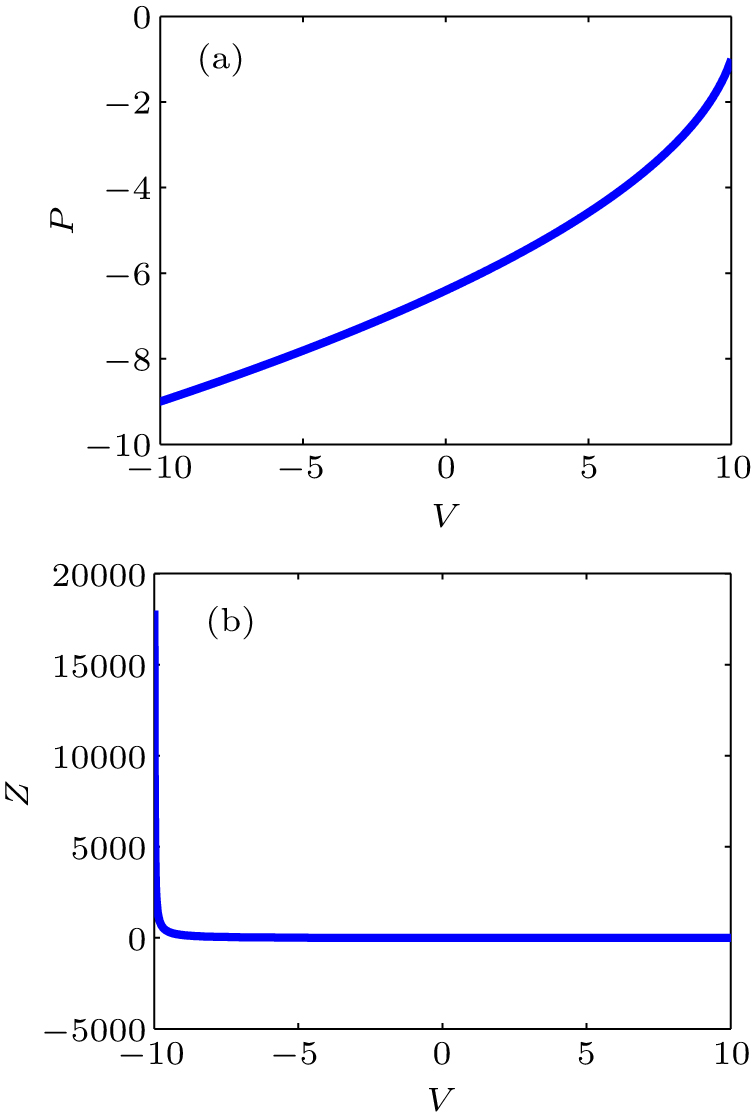
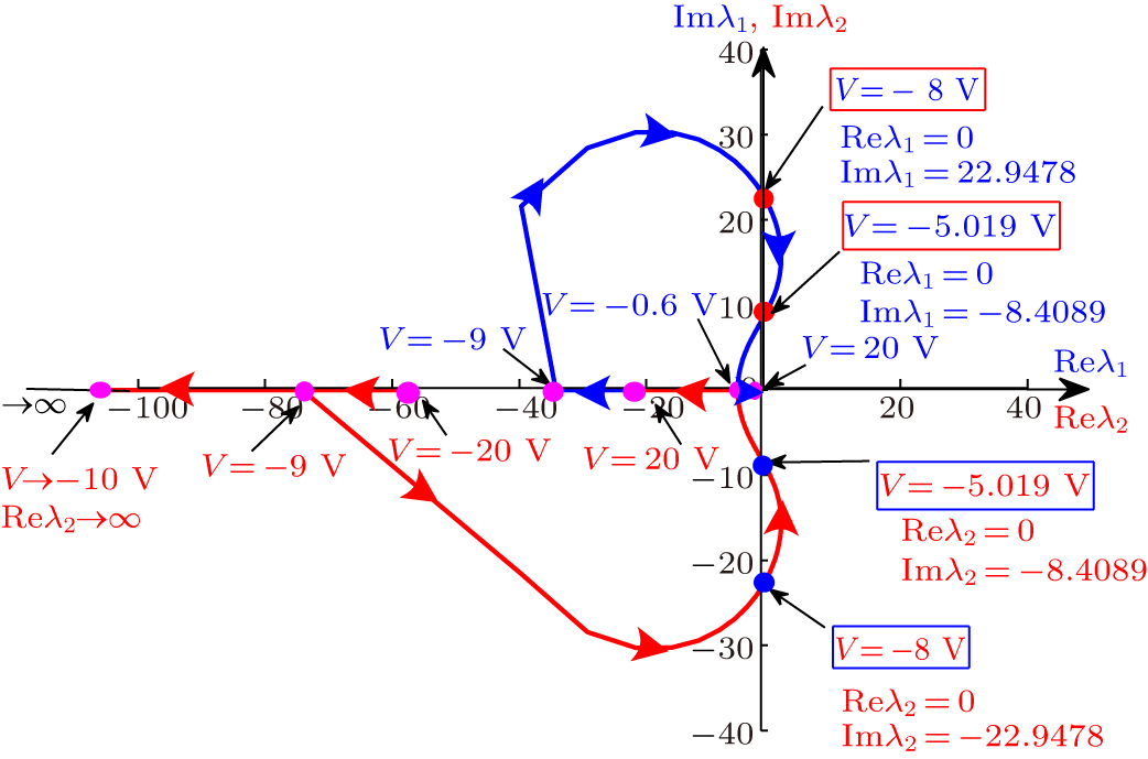
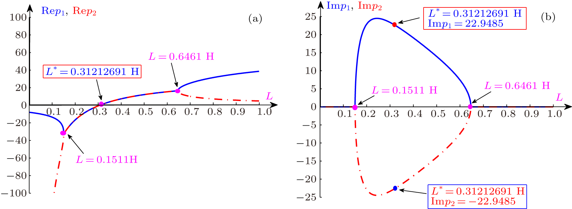
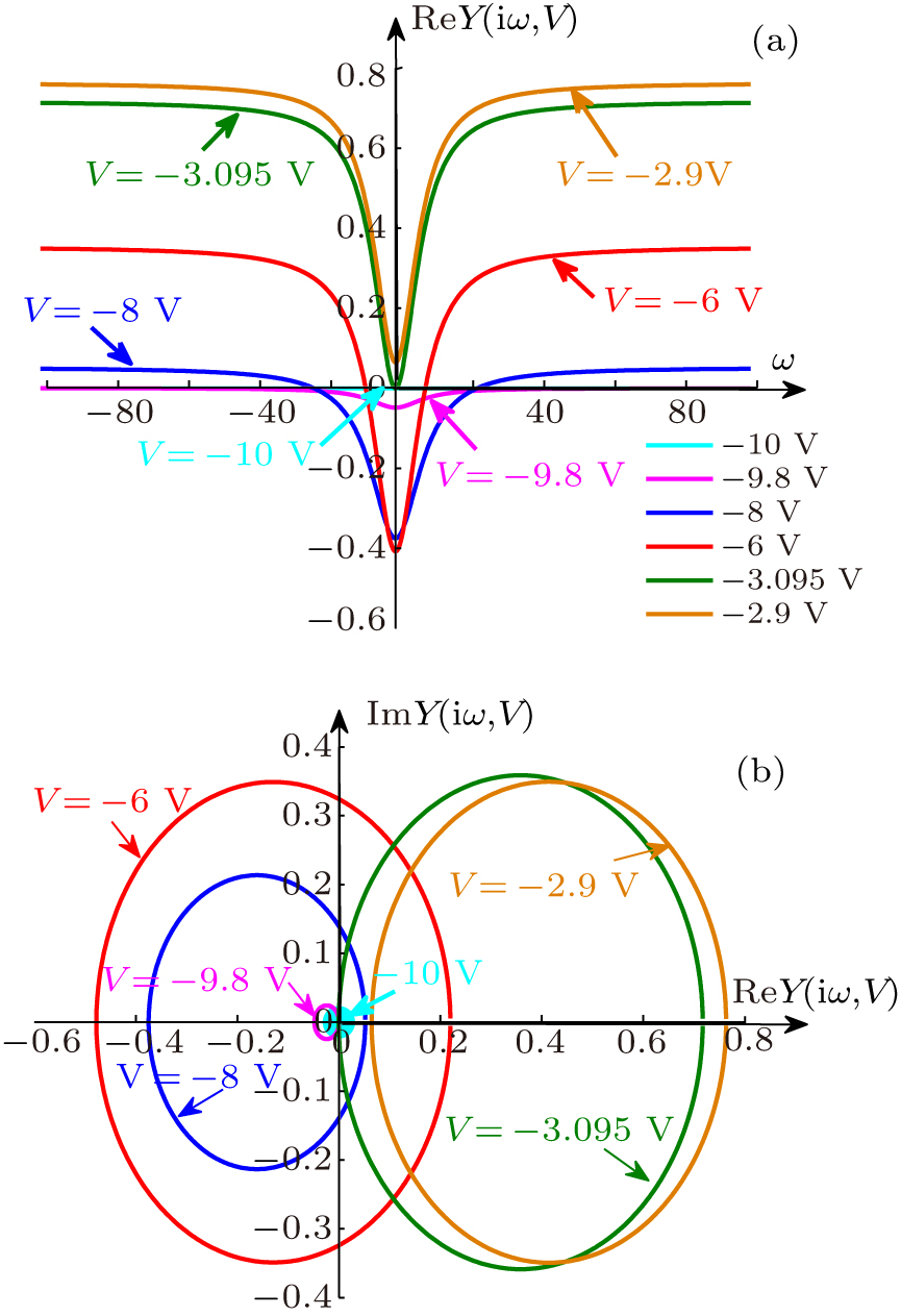
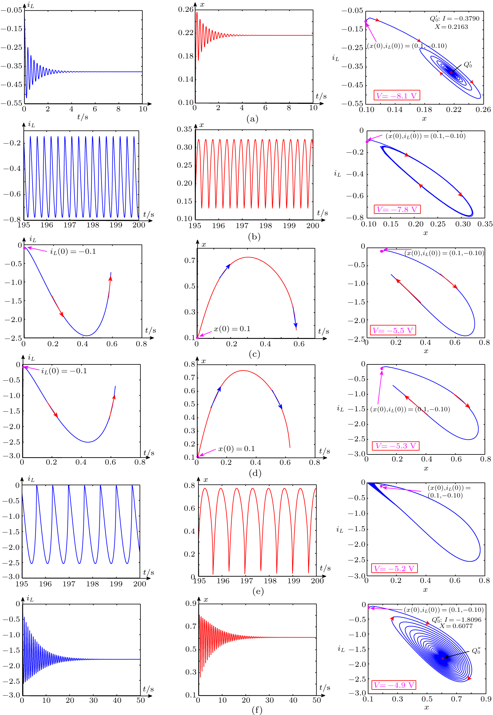
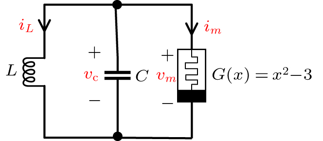
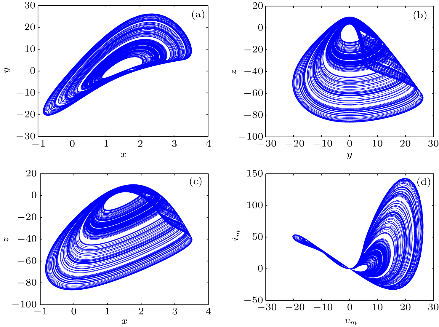
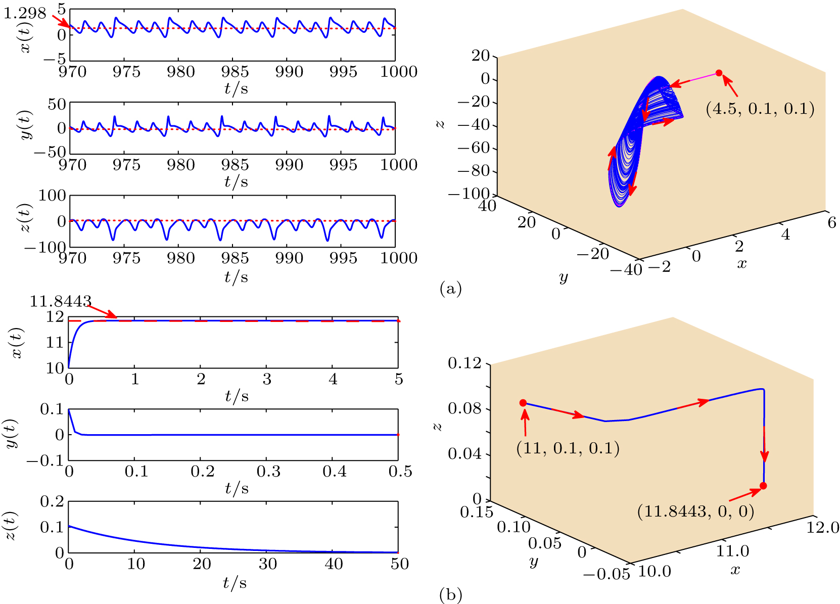
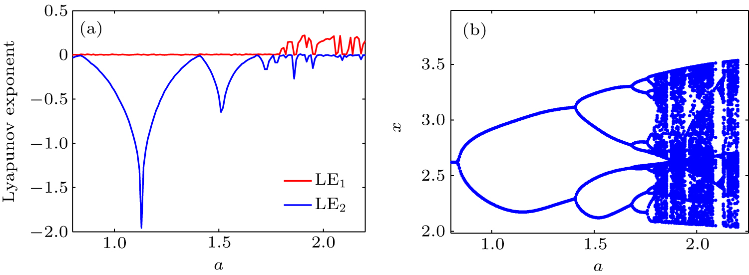
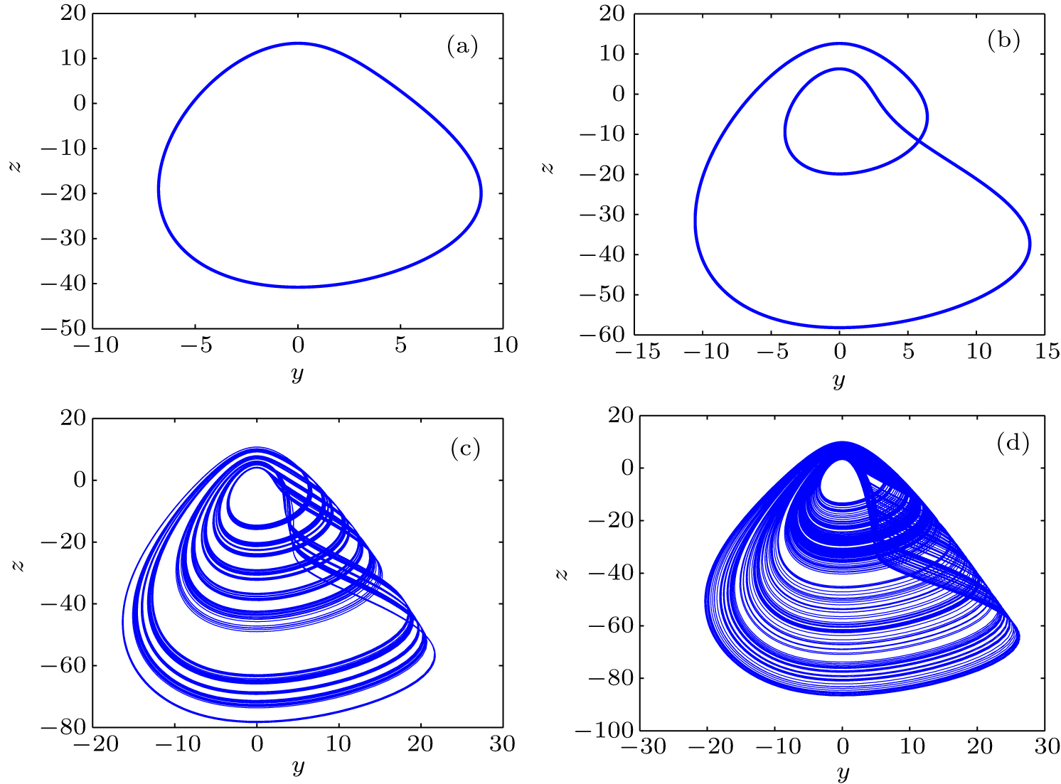
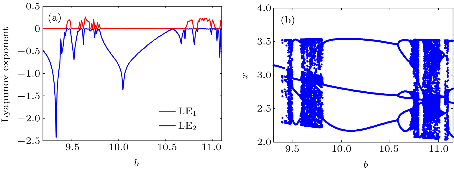
Abstract Complexity and abundant dynamics may arise in locally-active systems only, in which locally-active elements are essential to amplify infinitesimal fluctuation signals and maintain oscillating. It has been recently found that some memristors may act as locally-active elements under suitable biasing. A number of important engineering applications would benefit from locally-active memristors. The aim of this paper is to show that locally-active memristor-based circuits can generate periodic and chaotic oscillations. To this end, we propose a non-volatile locally-active memristor, which has two asymptotically stable equilibrium points (or two non-volatile memristances) and globally-passive but locally-active characteristic. At an operating point in the locally-active region, a small-signal equivalent circuit is derived for describing the characteristics of the memristor near the operating point. By using the small-signal equivalent circuit, we show that the memristor possesses an edge of chaos in a voltage range, and that the memristor, when connected in series with an inductor, can oscillate about a locally-active operating point in the edge of chaos. And the oscillating frequency and the external inductance are determined by the small-signal admittance Y(iω). Furthermore, if the parasitic capacitor in parallel with the memristor is considered in the periodic oscillating circuit, the circuit generates chaotic oscillations.
|
Received: 22 April 2020
Revised: 07 June 2020
Accepted manuscript online: 18 June 2020
|
| Fund: the National Natural Science Foundation of China (Grant No. 61771176). |
|
Corresponding Authors:
†Corresponding author. E-mail: wanggyi@163.com
|
Cite this article:
Wen-Yu Gu(谷文玉), Guang-Yi Wang(王光义), Yu-Jiao Dong(董玉姣), and Jia-Jie Ying(应佳捷) Nonlinear dynamics in non-volatile locally-active memristor for periodic and chaotic oscillations 2020 Chin. Phys. B 29 110503
|
| [1] |
|
| [2] |
|
| [3] |
Strukov D B, Snider G S, Stewart D R, Stanley Williams R 2008 Nature 453 80 DOI: 10.1038/nature06932 |
| [4] |
|
| [5] |
|
| [6] |
|
| [7] |
|
| [8] |
Prezioso M, Merrikh-Bayat F, Hoskins B D, Adam G C, Likharev K K, Strukov D B 2015 Nature 521 61 DOI: 10.1038/nature14441 |
| [9] |
|
| [10] |
|
| [11] |
|
| [12] |
|
| [13] |
|
| [14] |
Mainzer K, Chua L 2013 The local activity principle: The cause of complexity and symmetric breaking London Imperial College 146 159
|
| [15] |
|
| [16] |
|
| [17] |
|
| [18] |
|
| [19] |
Jin P P, Wang G Y, Lu H H C, Tyrone F 2017 IEEE Trans. Circuits & Systems II Express Briefs 65 246 DOI: 10.1109/TCSII.2017.2735448 |
| [20] |
|
| [21] |
|
| [22] |
|
| [23] |
Weiher M, Herzig M, Tetzlaff R, Ascoli A, Mikolajick T, Slesazeck S 2019 IEEE Transactions on Circuits and Systems I: Regular Papers 66 2627 DOI: 10.1109/TCSI.8919 |
| [24] |
|
| [25] |
|
| [26] |
|
| [27] |
|
| [28] |
Chua L, Desoer C A, Kuh E S 1987 Linear and Nonlinear Circuits New York McGraw-Hill
|
| [29] |
|
| [30] |
|
| [31] |
|
| No Suggested Reading articles found! |
|
|
Viewed |
|
|
|
Full text
|
|
|
|
|
Abstract
|
|
|
|
|
Cited |
|
|
|
|
Altmetric
|
|
blogs
Facebook pages
Wikipedia page
Google+ users
|
Online attention
Altmetric calculates a score based on the online attention an article receives. Each coloured thread in the circle represents a different type of online attention. The number in the centre is the Altmetric score. Social media and mainstream news media are the main sources that calculate the score. Reference managers such as Mendeley are also tracked but do not contribute to the score. Older articles often score higher because they have had more time to get noticed. To account for this, Altmetric has included the context data for other articles of a similar age.
View more on Altmetrics
|
|
|