|
|
|
Dynamics of the two-SBT-memristor-based chaotic circuit |
| Mei Guo(郭梅), Meng Zhang(张萌), Ming-Long Dou(窦明龙), Gang Dou(窦刚)†, and Yu-Xia Li(李玉霞)‡ |
| College of Electrical Engineering and Automation, Shandong University of Science and Technology, Qingdao 266590, China |
|
|
|
|
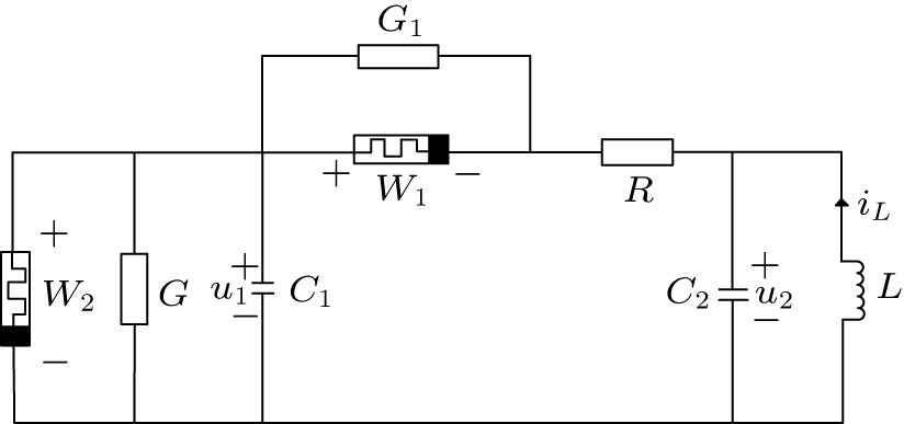
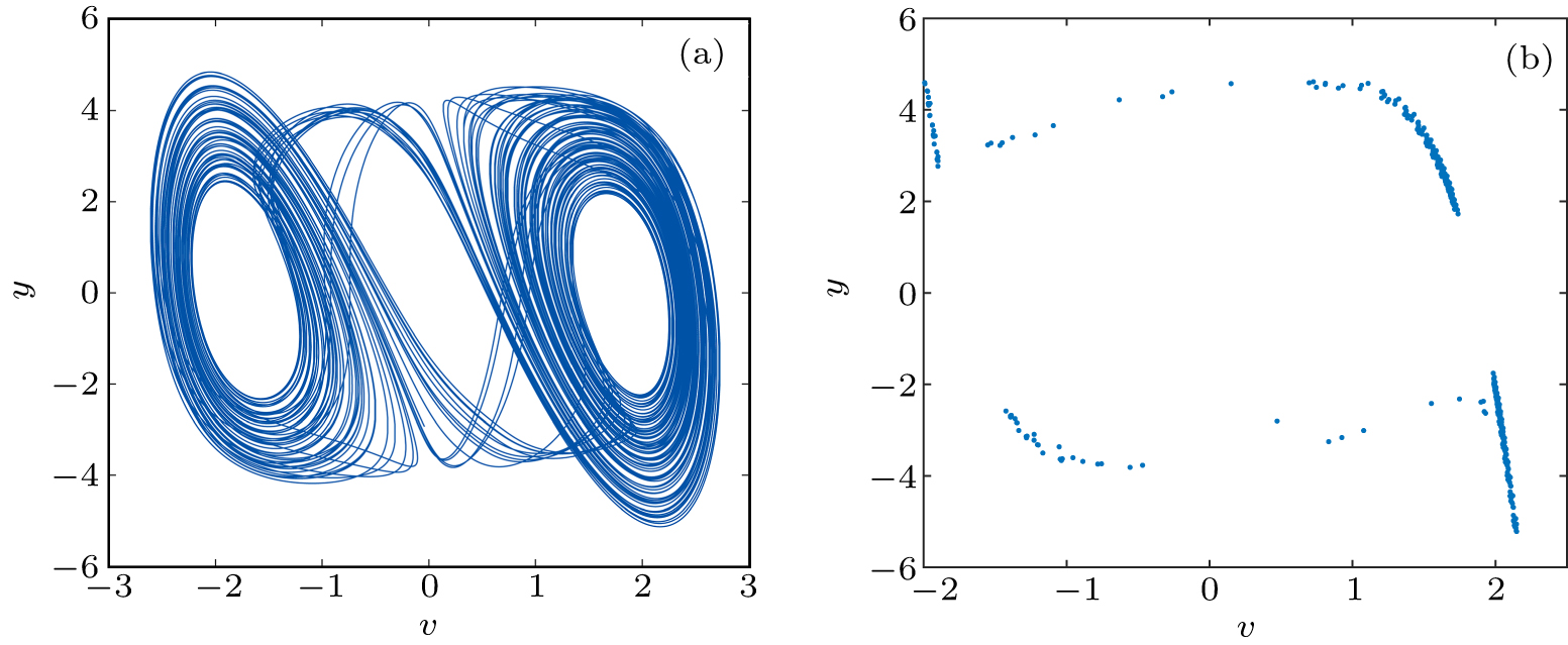
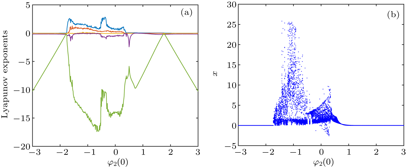
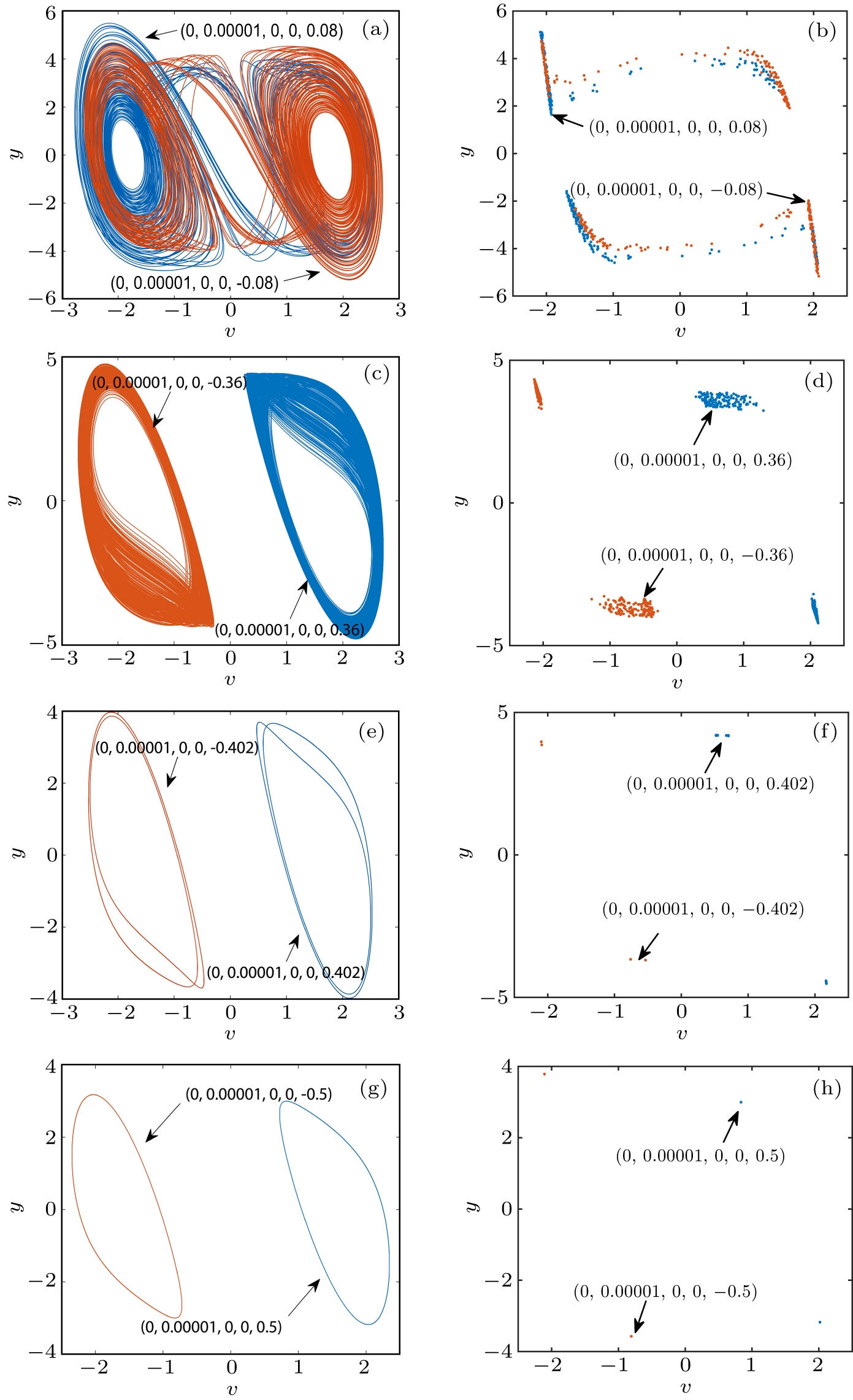
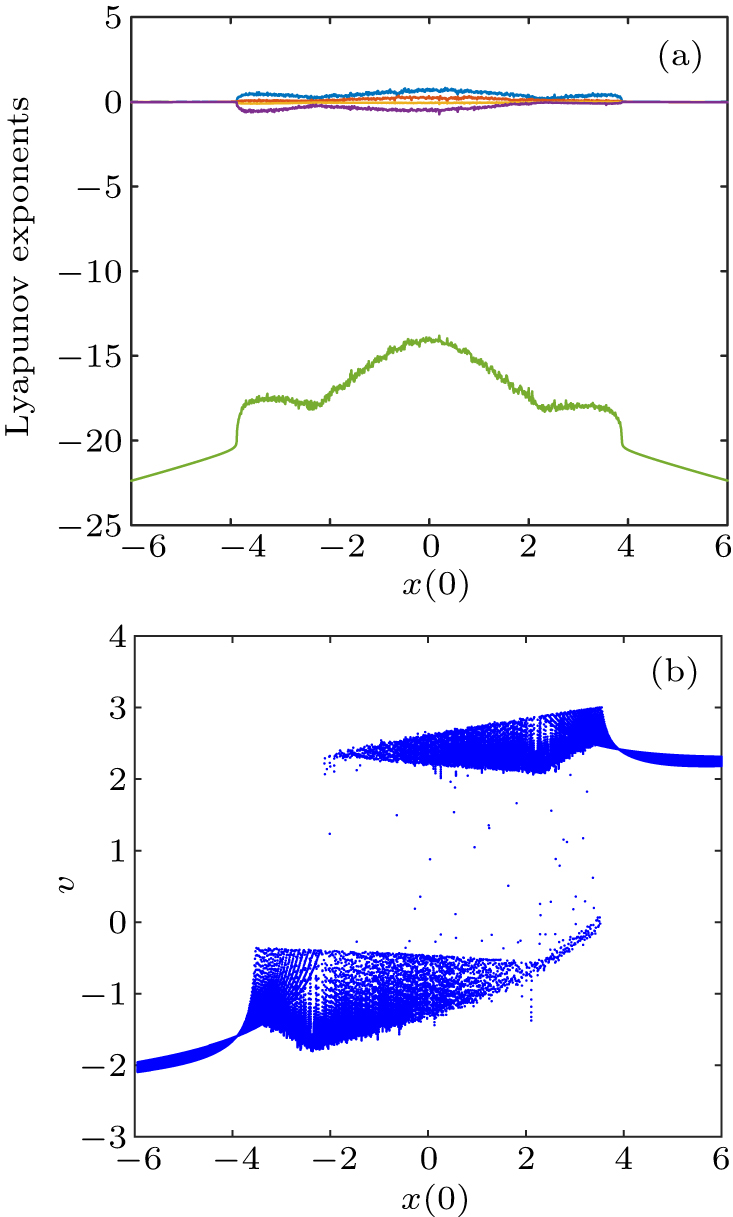
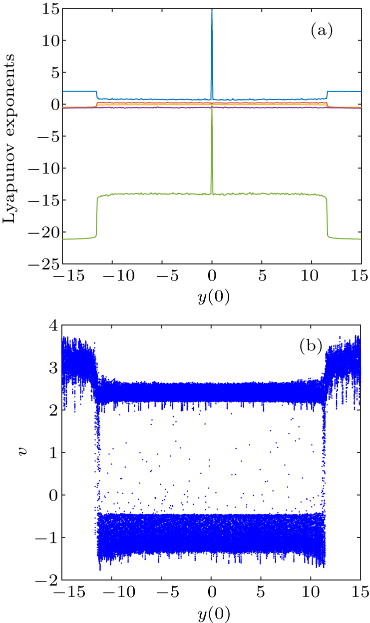
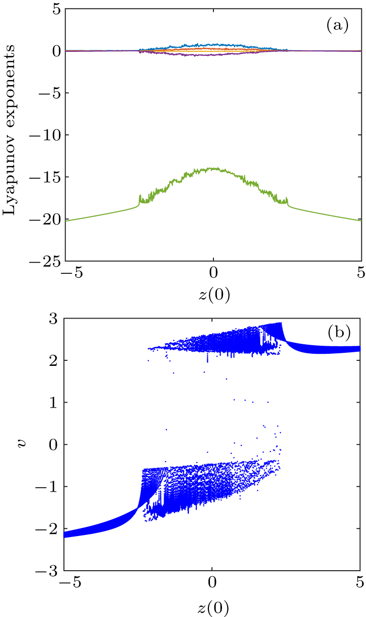
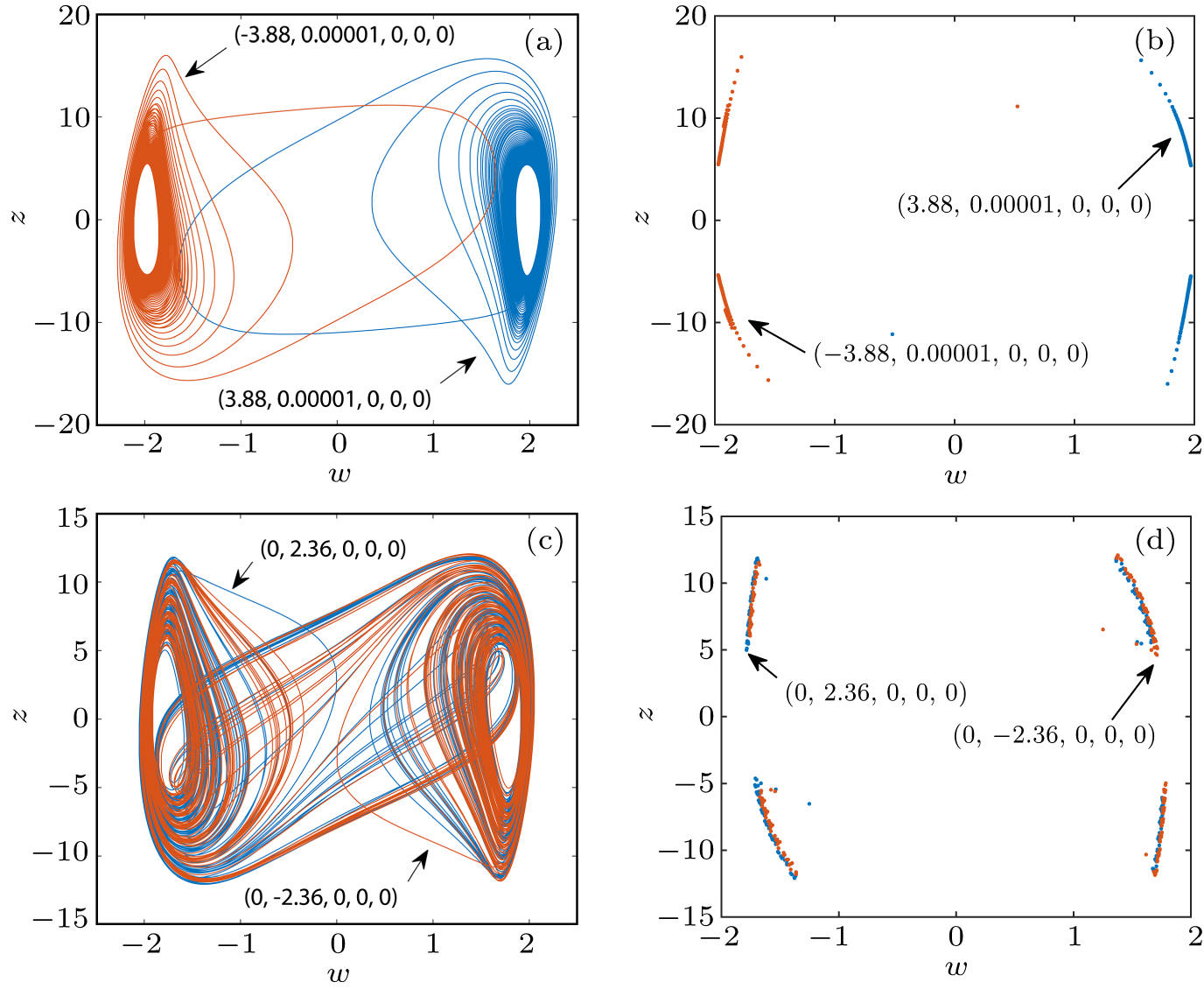
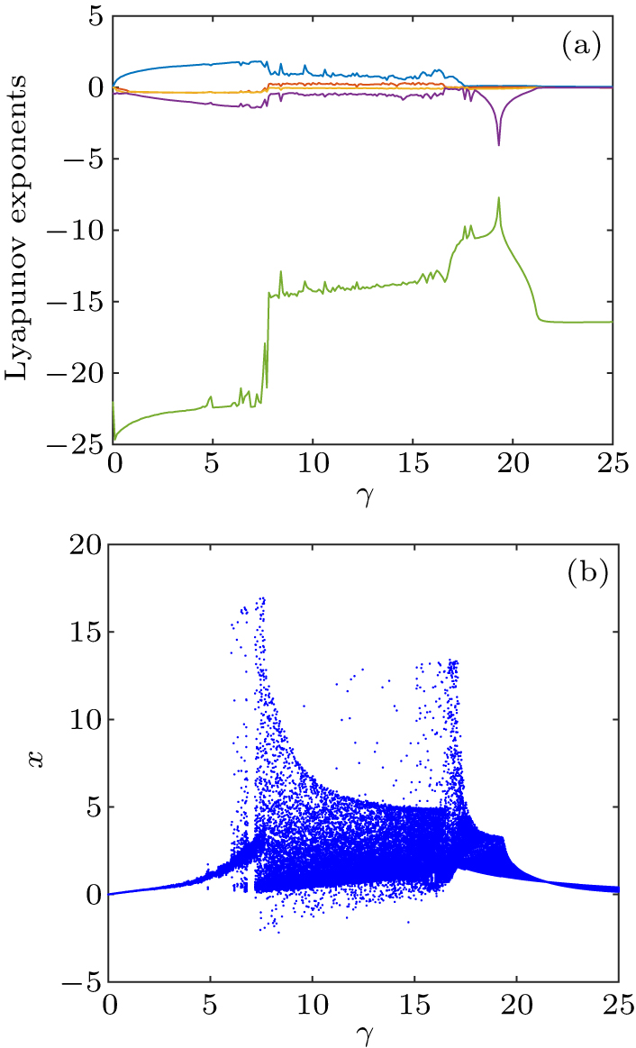
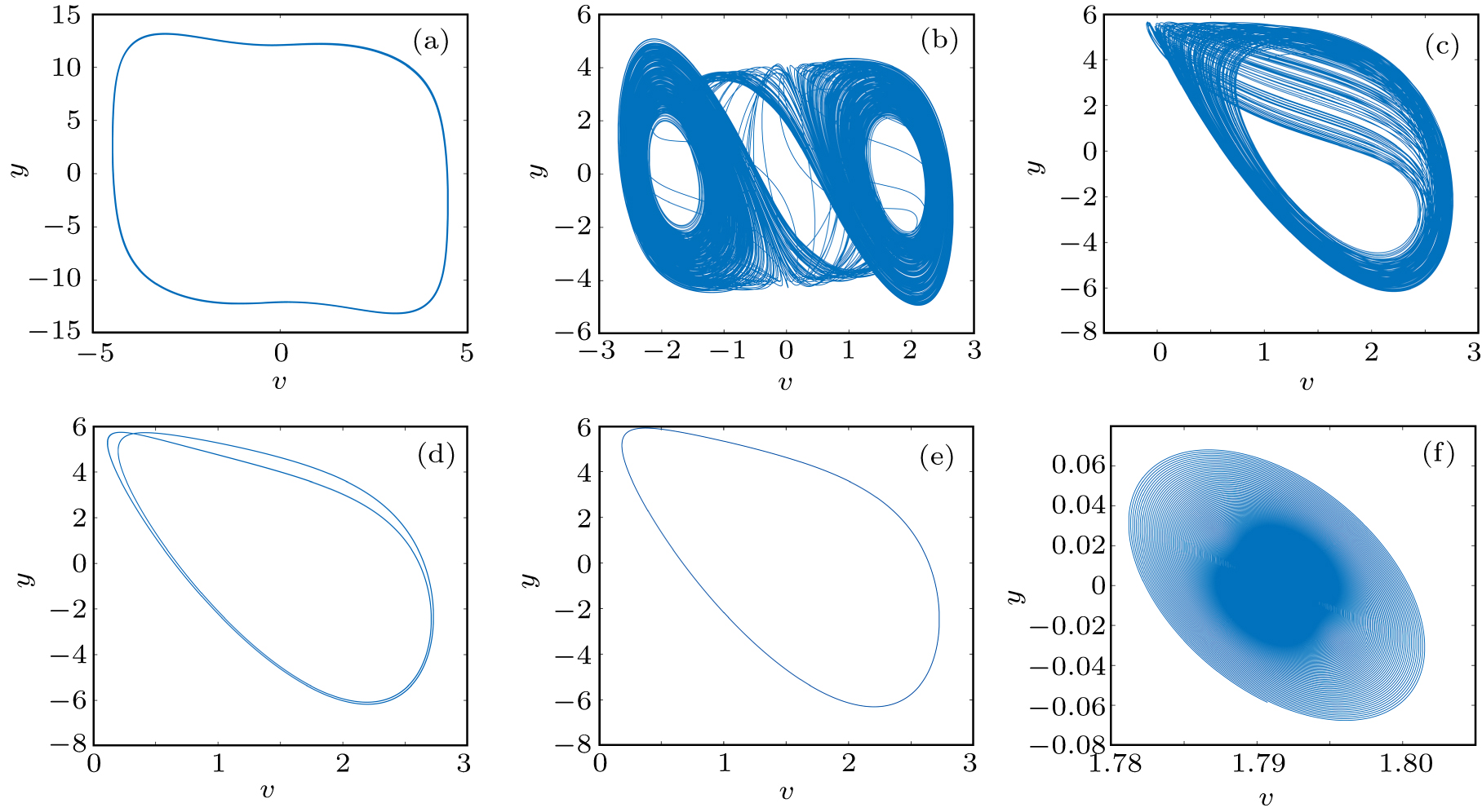
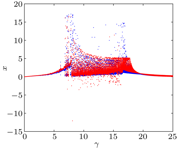
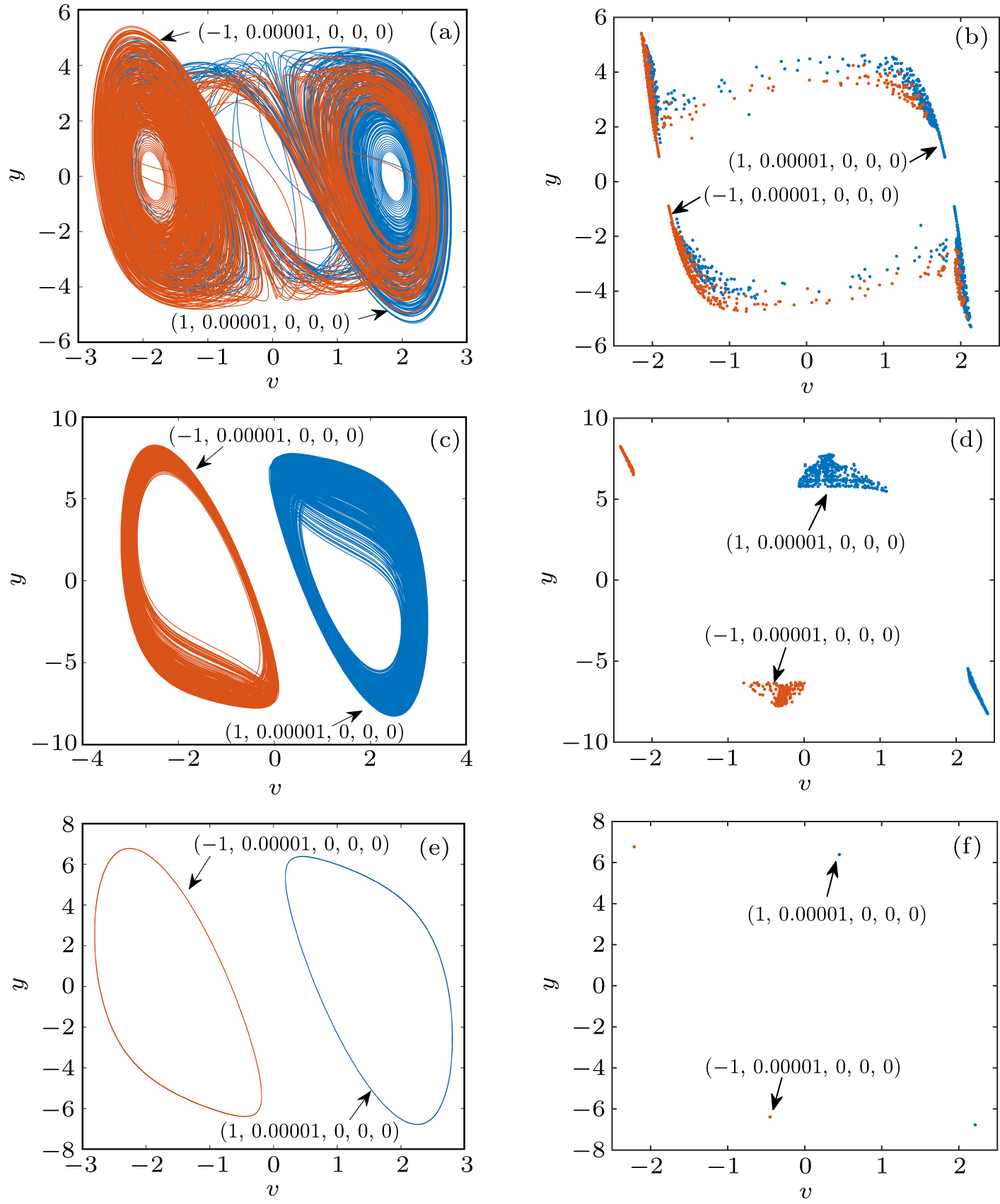
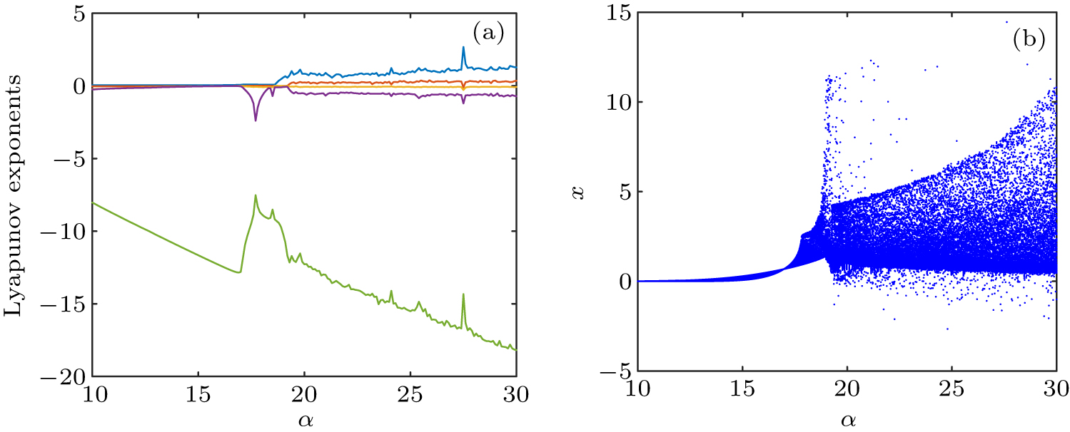
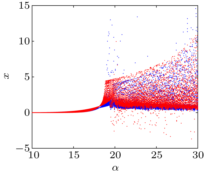
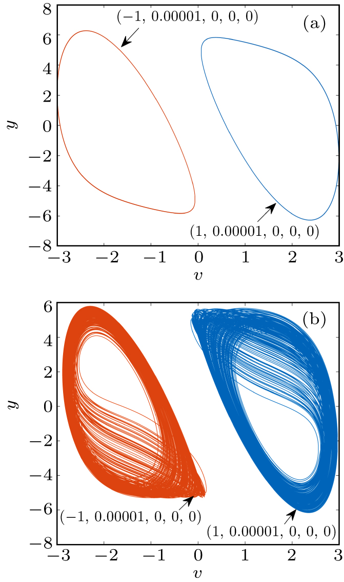
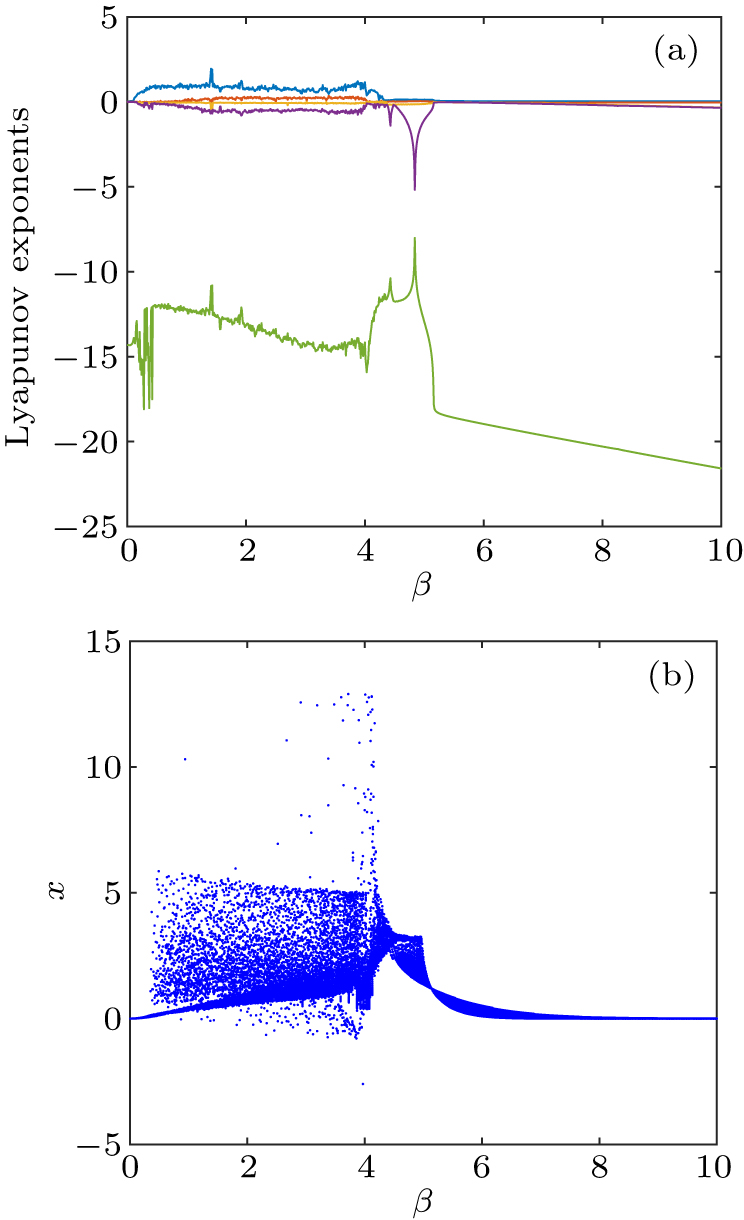
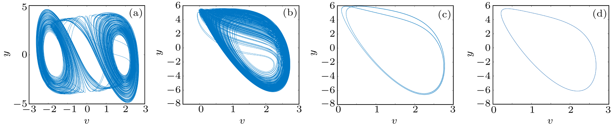
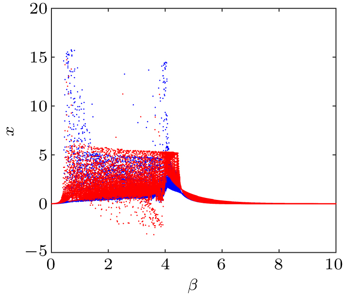
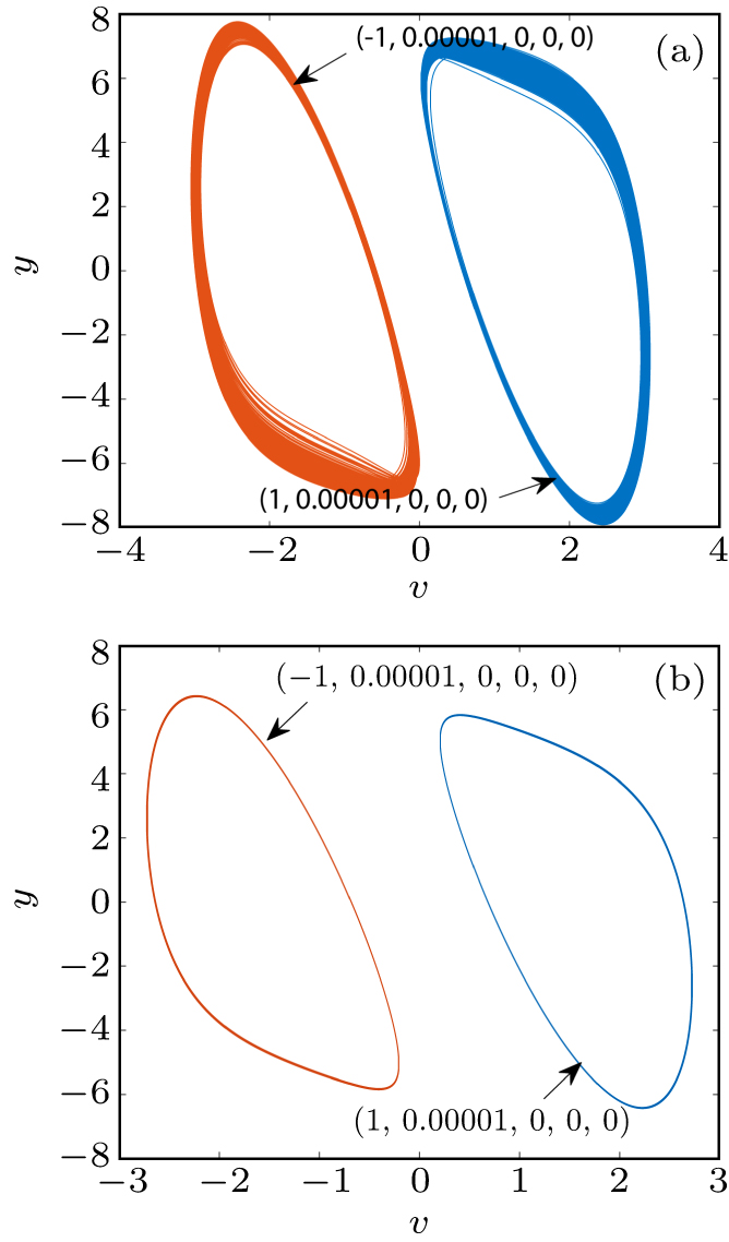
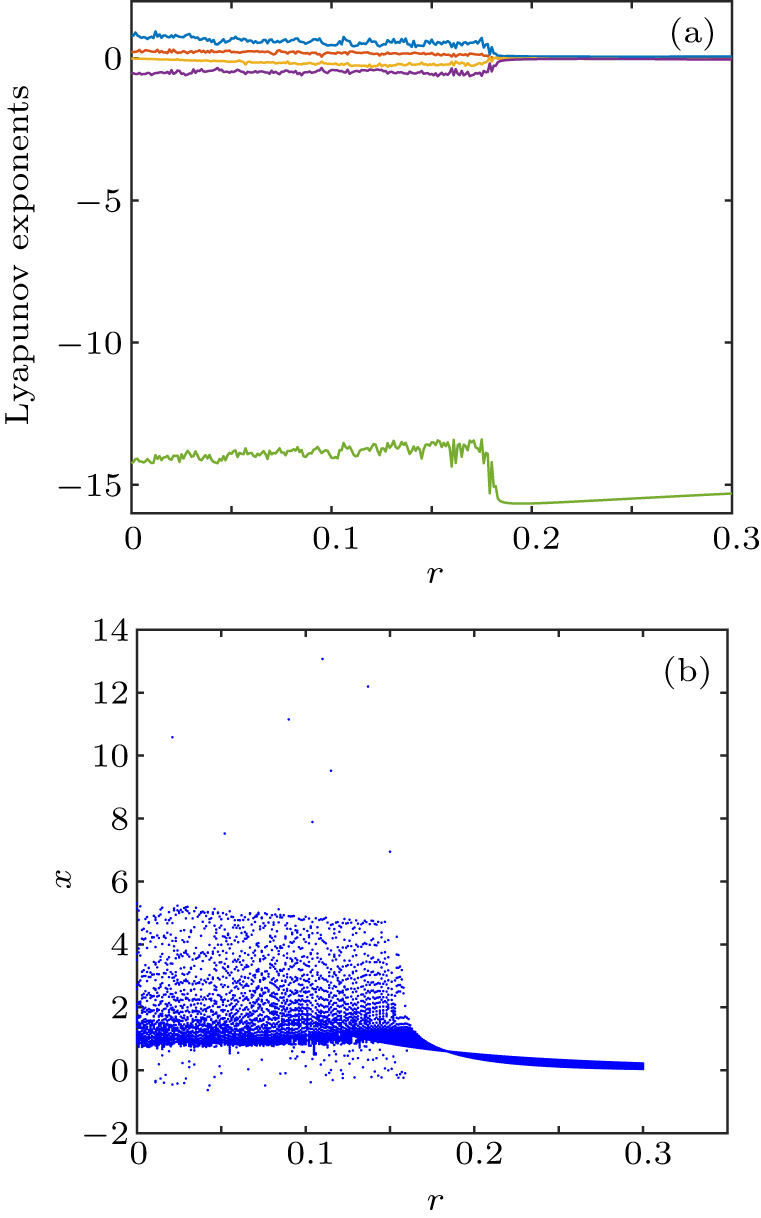
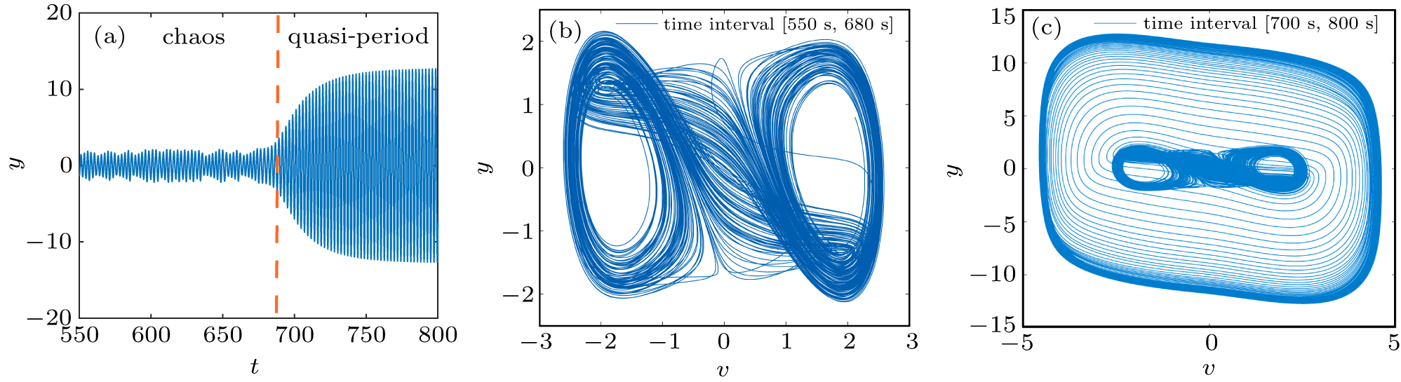
Abstract A two-SBT-memristor-based chaotic circuit was proposed. The stability of the equilibrium point was studied by theoretical analysis. The close dependence of the circuit dynamic characteristics on its initial conditions and circuit parameters was investigated by utilizing Lyapunov exponents spectra, bifurcation diagrams, phase diagrams, and Poincaré maps. The analysis showed that the circuit system had complex dynamic behaviors, such as stable points, period, chaos, limit cycles, and so on. In particular, the chaotic circuit produced the multistability phenomenon, such as coexisting attractors and coexisting periods.
|
Received: 15 August 2020
Revised: 04 September 2020
Accepted manuscript online: 28 September 2020
|
| Fund: the National Natural Science Foundation of China (Grant Nos. 61703247 and 61703246), the Qingdao Science and Technology Plan Project, China (Grant No. 19-6-2-2-cg), the Elite Project of Shandong University of Science and Technology, and the Taishan Scholar Project of Shandong Province of China. |
|
Corresponding Authors:
†Corresponding author. E-mail: dougang521@sdust.edu.cn ‡Corresponding author. E-mail: yuxiali2004@sdust.edu.cn
|
Cite this article:
Mei Guo(郭梅), Meng Zhang(张萌), Ming-Long Dou(窦明龙), Gang Dou(窦刚), and Yu-Xia Li(李玉霞) Dynamics of the two-SBT-memristor-based chaotic circuit 2020 Chin. Phys. B 29 110505
|
| [1] |
|
| [2] |
|
| [3] |
|
| [4] |
|
| [5] |
Borghetti J, Snider G S, Kuekes P J, Yang J J, Stewart D R, Williams R S 2010 Nature 464 873 DOI: 10.1038/nature08940 |
| [6] |
|
| [7] |
|
| [8] |
|
| [9] |
|
| [10] |
|
| [11] |
|
| [12] |
|
| [13] |
|
| [14] |
|
| [15] |
|
| [16] |
|
| [17] |
|
| [18] |
|
| [19] |
Fozin T F, Ezhilarasu P M, Tabekoueng Z N, Leutcho G D, Kengne J, Thamilmaran K, Mezatio A B, Pelap F B 2019 Chaos 29 113105 DOI: 10.1063/1.5121028 |
| [20] |
|
| [21] |
Buscarino A, Fortuna L, Frasca M, Gambuzza L V 2012 Chaos 22 023136 DOI: 10.1063/1.4729135 |
| [22] |
|
| [23] |
|
| [24] |
|
| [25] |
|
| [26] |
|
| [27] |
|
| [28] |
|
| [29] |
|
| [30] |
Guo M, Yang W Y, Xue Y B, Gao Z H, Yuan F, Dou G, Li Y X 2019 Chaos 29 043114 DOI: 10.1063/1.5089293 |
| [31] |
|
| [32] |
|
| [33] |
|
| [34] |
|
| [35] |
|
| [36] |
|
| [37] |
|
| No Suggested Reading articles found! |
|
|
Viewed |
|
|
|
Full text
|
|
|
|
|
Abstract
|
|
|
|
|
Cited |
|
|
|
|
Altmetric
|
|
blogs
Facebook pages
Wikipedia page
Google+ users
|
Online attention
Altmetric calculates a score based on the online attention an article receives. Each coloured thread in the circle represents a different type of online attention. The number in the centre is the Altmetric score. Social media and mainstream news media are the main sources that calculate the score. Reference managers such as Mendeley are also tracked but do not contribute to the score. Older articles often score higher because they have had more time to get noticed. To account for this, Altmetric has included the context data for other articles of a similar age.
View more on Altmetrics
|
|
|