Effect of fluence and ambient environment on the surface and structural modification of femtosecond laser irradiated Ti
Umm-i-Kalsoom 1, 2, 3, †, , Bashir Shazia 2 , Ali Nisar 1, 2, 4 , Shahid Rafique M 5 , Husinsky Wolfgang 1 , Nathala Chandra S R 1 , Makarov Sergey V 6 , Begum Narjis 7
Institute for Applied Physics, Vienna University of Technology, Vienna, Austria
Centre for Advanced Studies in Physics, GC University Lahore, Pakistan
Department of Physics, The University of Lahore, Pakistan
Department of Basic Sciences and Humanities,University of Engineering and Technology Fasalabad, Pakistan
Department of Physics, University of Engineering and Technology Lahore, Pakistan
P. N. Lebedev Physics Institute RAS, Moscow, Russia
Department of Physics, COMSATS Institute of Information and Technology, Islamabad, Pakistan


† Corresponding author. E-mail: ummikalsoom551@gmail.com

Project supported by Österreichische Forschungsfödergesellschaft (FFG) (Grant No. 834325).

Abstract
Abstract

Under certain conditions, ultrafast pulsed laser interaction with matter leads to the formation of self-organized conical as well as periodic surface structures (commonly reffered to as, laser induced periodic surface structures, LIPSS). The purpose of the present investigations is to explore the effect of fsec laser fluence and ambient environments (Vacuum & O 2 ) on the formation of LIPSS and conical structures on the Ti surface. The surface morphology was investigated by scanning electron microscope (SEM). The ablation threshold with single and multiple ( N = 100) shots and the existence of an incubation effect was demonstrated by SEM investigations for both the vacuum and the O 2 environment. The phase analysis and chemical composition of the exposed targets were performed by x-ray diffraction (XRD) and energy dispersive x-ray spectroscopy (EDS), respectively. SEM investigations reveal the formation of LIPSS (nano & micro). FFT d-spacing calculations illustrate the dependence of periodicity on the fluence and ambient environment. The periodicity of nano-scale LIPSS is higher in the case of irradiation under vacuum conditions as compared to O 2 . Furthermore, the O 2 environment reduces the ablation threshold. XRD data reveal that for the O 2 environment, new phases (oxides of Ti) are formed. EDS analysis exhibits that after irradiation under vacuum conditions, the percentage of impurity element (Al) is reduced. The irradiation in the O 2 environment results in 15% atomic diffusion of oxygen.

1. Introduction

Femtosecond (fsec) laser radiation can under certain conditions induce “periodic surface structures” or LIPSS on the surfaces of metals, semiconductors, and dielectrics. The most important parameter which determines the development of these structures is the laser fluence. The formation of ripples have been observed only in specific fluence regimes (relatively low and moderate laser fluence). Furthermore, a possibility for controlling the periodicity of LIPSS can be achieved by adjusting laser fluence, the number of pulses, pulse width, etc. In particular, the environmental conditions under which the target is exposed. [ 1 , 2 ] Oliveira et al. [ 3 ] studied the formation of LIPSS and microcolumns on the surface of Ti for various fsec laser fluences (0.5–2 J/cm 2 ) in stationary and scanning modes. They concluded that ripples convert into microcolumns as they are subjected to fluences near the melting threshold of Ti. The formation of a regular array of sharp nano/micro conical structures on Ti using fsec lasers in non-reactive (vacuum and He) as well as in reactive medium (SF 6 , air or HCl) has also been reported. [ 4 ] The importance to explore the structuring of Ti is that it has a vast variety of applications in various fields, like fuel cells, biomedical engineering, material science, etc. [ 3 , 5 7 ]

In this paper we report the dependence of the growth of conical structures and LIPSS on laser fluence and the ambient environment (Vacuum & O 2 ). The surface properties of the laser-irradiated Ti samples have been analyzed by using SEM, whereas structural modification such as phase analysis and chemical composition were explored by XRD and EDS.

2. Experimental setup

A chirped pulse amplification (CPA) Ti: Sapphire laser amplifier seeded from a mode-locked Ti: Sapphire oscillator (FEMTOPOWER PRO) was used for the ablation of Ti targets. The system was operating at a central wavelength of about 800 nm, a repetition rate of 1 kHz, with a pulse duration of about 30 fsec. The beam was focused through a lens of focal length 20 cm.

Rectangular-shaped Ti targets with a dimension of 20 mm × 15 mm × 3 mm were ground, polished (upto a roughness value of 1 μm), and ultrasonically cleaned with acetone for 30 minutes before irradiation. These targets were mounted on a target holder placed in a vacuum chamber that was evacuated to a base pressure of the order of 10 −3 mbar. Two sets of experiments were performed. (i) Exposure of Ti targets by a single laser pulse for various energies (20, 30, 40, 50, 60, 70, 80, 130, 180, and 230 μJ) corresponding to fluences of 0.38, 0.57, 0.86, 1.00, 1.13, 1.27, 1.52, 2.47, 3.42, and 4.37 J·cm −2 , respectively.

The results obtained from this set of experiments were mainly utilized to determine the single shot ablation threshold fluence and to estimate the incubation coefficient of Ti. The ablation threshold was evaluated by plotting the squared spot diameter ( D 2 ) (obtained by SEM micrographs) versus the logarithm of the laser pulse energy. From the slope of this graph the value of spot size is calculated to be 58 μm and the threshold energy was determined by extrapolating the graph to zero. (2) Exposure of Ti targets to 100 laser pulses for various fluences of 0.86, 1.00, 1.13, 1.27, 1.52, 2.47, 3.42, and 4.37 J·cm −2 . Results obtained in the second set of experiments have been presented. Both sets of experiments were performed under a vacuum as well as in the O 2 environment at a pressure of 133 mbar.

Surface morphology of the irradiated Ti targets was investigated by using SEM (FEI-QUANTA 200F, Netherlands). The XRD technique was employed for phase analysis by using an X’Pert PRO (MPD) x-ray diffractometer. The EDS analysis was performed for chemical analysis of irradiated targets.

3. Results and discussion
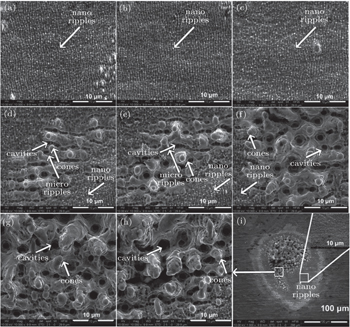
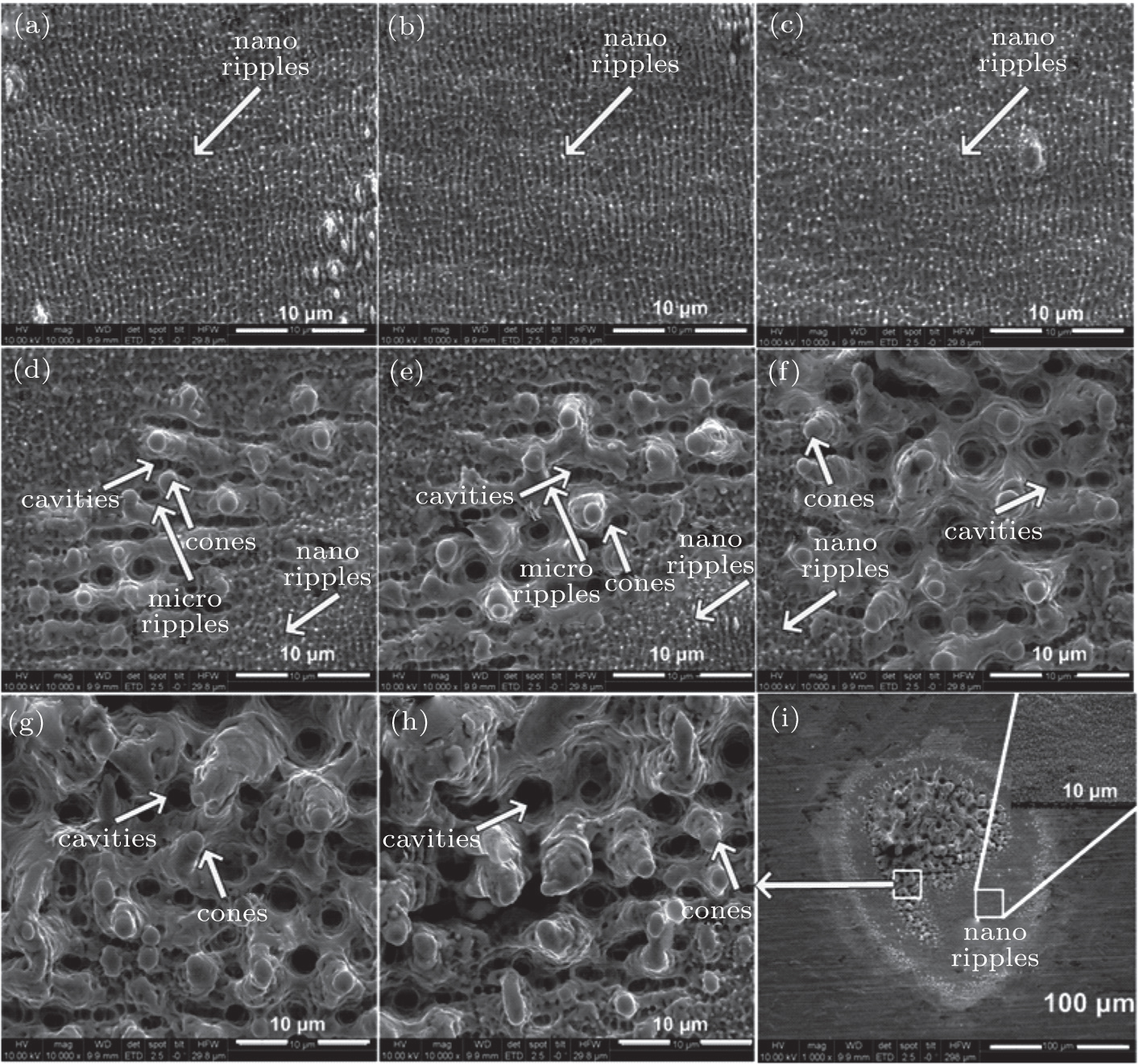
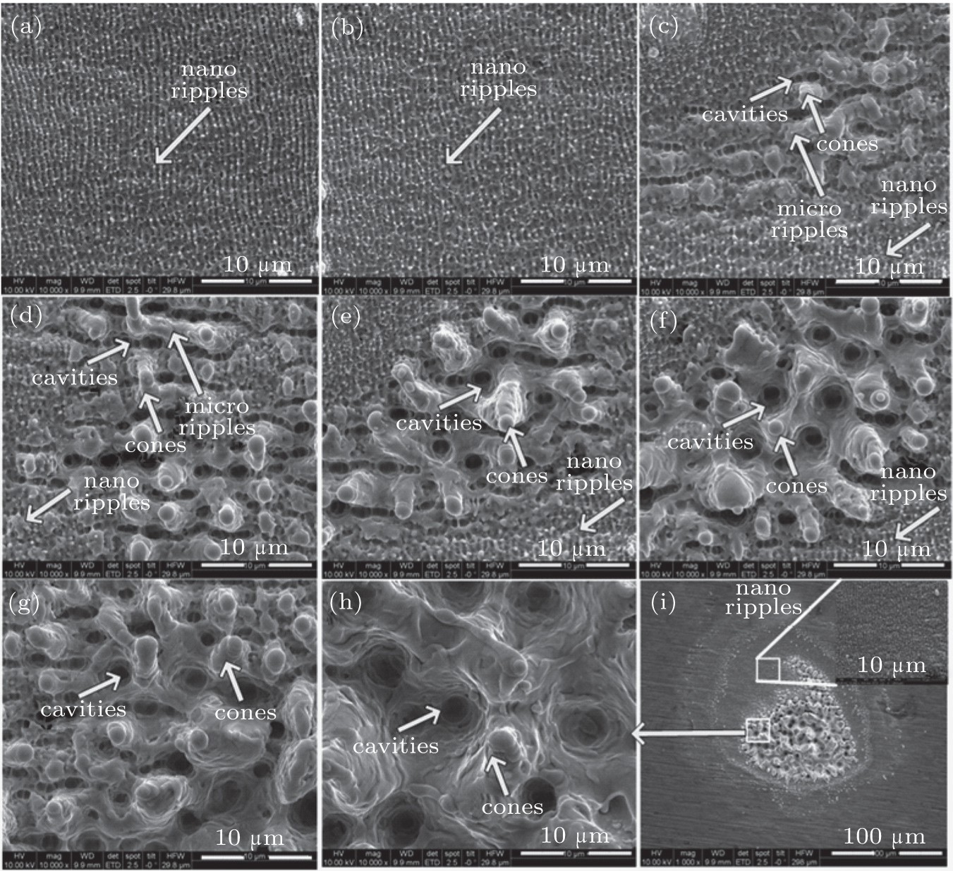
3.1. Morphological results using SEM analysis

SEM micrographs in figure 1 show the modified surface of Ti for various laser fluences of (a) 0.86, (b) 1.00, (c) 1.13, (d) 1.27, (e) 1.52, (f) 2.47, (g) 3.42, and (h) 4.37 J·cm −2 . (i) Full view for the fluence value of 4.37 J·cm −2 after irradiation with 100 laser shots under vacuum conditions. Various features, like, craters, cones, and LIPSS (ripples) are observed on the surface of irradiated Ti. Ripples formed on the irradiated Ti surface are of two kinds, i.e., micro and nano scale. It has been demonstrated in Refs. [ 8 ] and [ 9 ], that nano-scale (sub-wavelength) ripples are oriented perpendicular to the direction of linear polarization of laser beam. Whereas the micro-ripples are oriented in the direction parallel to the linear polarization of the incident laser beam. Nano-scale ripples are observed for all maximal laser fluences but in different areas of the laser spot. For lower maximal fluences (0.86 to 1.13 J·cm −2 ), formation of nano-scale ripples is observed closer to the center. However, at high maximal fluences, ranging from 1.27 to 4.37 J·cm −2 , nanoripples are formed only in the peripheral ablated areas. While at the center features including microscale ripples, conical structures and cavities are observed as seen in Figs. 1(d) 1(h) . The average spacing of micoripples is about 2 μm, which is significantly greater than the incident laser wavelength (Fig. 1(d) ). In the highest fluence areas (2.47–4.37 J·cm −2 ) (Figs. 1(f) 1(h) ), micro-scale ripples also vanish completely and only microconical structures and cavities remain visible. This implies that for both nano as well as microscale ripples, there is a certain fluence window below which they are not formed, above which they are destroyed. However, the threshold fluence for the formation of nanoripples is smaller than that for microripples. This information is compatible with previously reported work by many research groups. [ 9 , 10 ]

Fig. 1. SEM images revealing the variation in the surface morphology of Ti after ablation by 100 pulses of fsec laser at wavelength of 800 nm, pulse duration of 30 fsec, and repetition rate of 1 kHz for various fluences of (a) 0.86, (b) 1.0, (c) 1.13, (d) 1.27, (e) 1.52, (f) 2.47, (g) 3.42, (h) 4.37 J·cm −2 and (i) full view of the ablated region for a fluence value of 4.37 J·cm −2 under vacuum (10 −3 mbar) conditions.

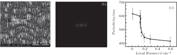
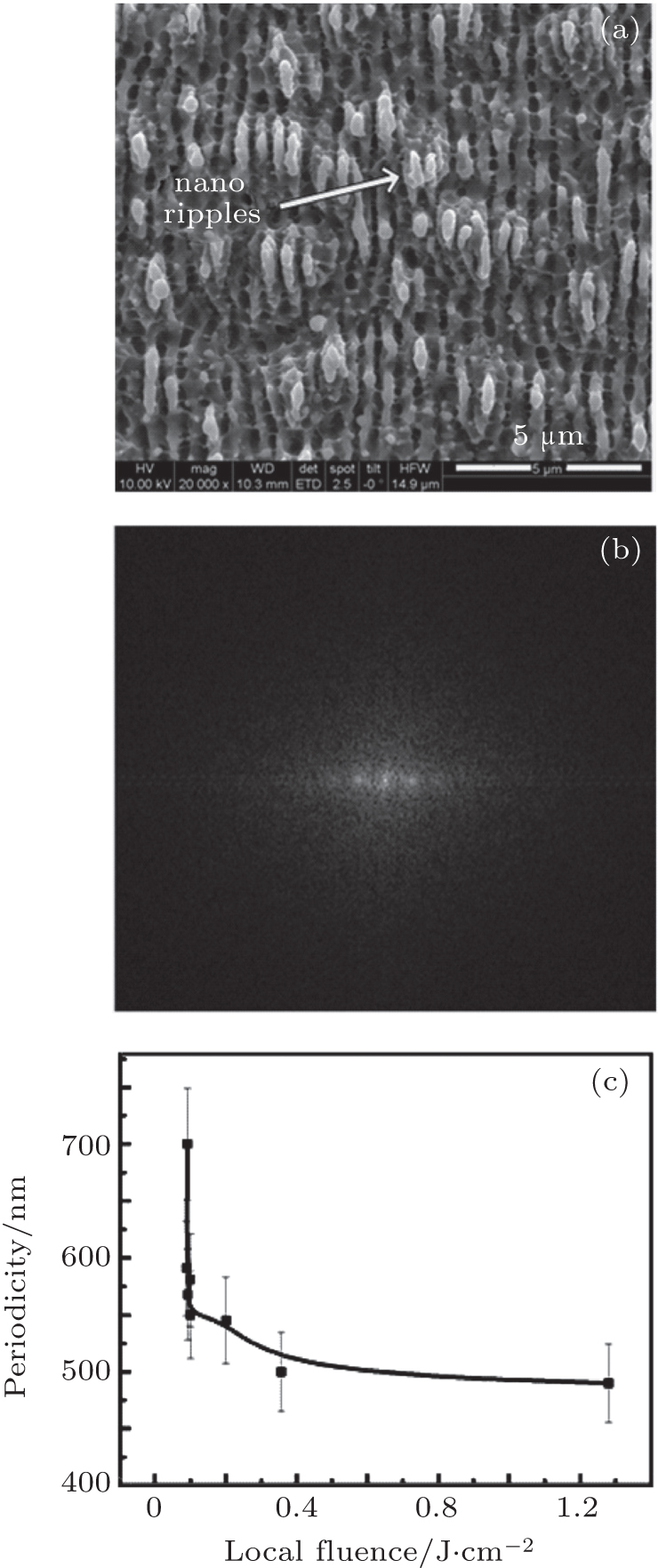
For precise measurement of nanoripples formed on the Ti surface, fast Fourier transform (FFT) was employed for all fluences. The enlarged SEM view of nano-ripple formation of Fig. 1(a) is shown in Fig. 2(a) . Figure 2(b) corresponds to the 2D FFT image for Figs. 1(a) and 2(c) reveals the variation in periodicity of nano-LIPSS for various laser fluences.

Fig. 2. (a) Magnified view of nano-LIPSS formation of Figs. 1(a) and 1(b). Two-dimensional fast Fourier transform (FFT) spectra of Figs. 1(a) and 1(c) . The variation in periodicity of nano-LIPSS for various local fluences using FFT after ablation of Ti under vacuum (10 −3 mbar) condition by 100 pulses of fsec laser at wavelength of 800 nm, pulse duration of 30 fsec, and repetition rate of 1 kHz.

In order to reveal the variation in the LIPSS periodicity versus local fluence, the following equation was used to evaluate local fluence: [ 11 ]

where φ min is the local fluence for which nano-LIPPSS appears, φ 0 is the peak fluence, D LIPSS0 (128 to 91 μm) is the inner diameter of the surface region in which nano LIPSS are formed and ω 0 is the beam waist radius (58 μm). The values of local fluence vary from 0.08 to 1.28 J·cm −2 with the increase of peak fluence from 0.86 to 4.37 J·cm −2 . The periodicity of nano ripples reduces from 700 to 490 nm with the increase of local fluence from 0.08 to 1.28 J·cm −2 (for peak fluences from 0.86 to 4.78 J·cm −2 ) as shown in Fig. 2(c) .

The reduction in periodicity, for various semiconducting materials have been studied by different research groups. [ 12 , 13 ] This decrease in the periodicity has been explained on the basis of coupling between surface plasmons and incoming laser radiation. [ 13 ] As the surface gratings formed during the first few pulses, the resonant wavelength of surface plasmons undergo blueshift. This shift causes the reduction of periodicity with the increase of fluence or the number of pulses. The reduction in the periodicity can also be attributed to the increasing refractive index of Ti after enhancement of surface roughness due to laser irradiation that significantly affects the propagation of surface plasmons. [ 14 ] The generation of nanoripples has been explained on the basis of surface plasmons (SP’s) or a parametric instability. [ 15 ] During laser irradiation, the first few pulses create and enhance the surface roughness. Non-uniform free electron density due to this surface roughness plays a significant role in the development of nano-scale ripples. [ 16 ] The formation of nanoripples has also been explained on the basis of a parametric decay (stimulated Raman scattering) model. [ 10 ] In this model, the plasma wave travels slowly, at a speed of less than 10 −2 times the speed of light and an ion-enriched local area appears. Before the next peak of an electron wave arrives, ions experience a strong coulomb repulsive force causing a coulomb explosion. Through this process, periodic ripple structures may be formed. [ 10 ]

On the other hand, microripples are formed through rapid heating and melting of the surface layer followed by fast cooling under plasma pressure and gradients in the thermodynamic parameters. [ 17 ]

Laser-induced cavities can serve to compress the laser-induced plasma and therefore can initiate an extreme non-equilibrium state followed by self organization that results in the formation of micro ripples. [ 18 ] The formation of cavities under compressed plasma flow can be related to the violent boiling and bubble formation in the superheated liquid layer. Due to the turbulence and thrust of the boiling bubbles inside the liquid layer followed by a rapid cooling leads to the formation of cavities and frozen melt in the form of microconical structures. [ 19 ]

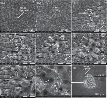
SEM images of Fig. 3 show the modified surface of Ti for various laser fluences. (i) Full view for the fluence value of 4.37 J·cm −2 after irradiation with 100 laser shots in O 2 environment at a pressure of 133 mbar. The formation of both nano and micro (1 μm) LIPSS is observed. They are similar in appearance to the ripples that have been observed under vacuum conditions (Fig. 1 ).

Fig. 3. SEM images revealing the variation in the surface morphology of Ti after ablation by 100 pulses of fsec laser at a wavelength of 800 nm, pulse duration of 30 fsec, and a repetition rate of 1 kHz for different fluences of (a) 0.86, (b) 1.0, (c) 1.13, (d) 1.27, (e) 1.52, (f) 2.47, (g) 3.42, and (h) 4.37 J·cm −2 . (i) Full view of ablated region for a fluence value of 4.37 J·cm −2 in O 2 at a pressure of 133 mbar.

Comparison of the two ambient environments, vacuum and O 2 (Figs. 1 and 3 ), shows that the fluence threshold for microstructure formation is lower in the case of oxygen, as compared to a vacuum environment. The presence of the gas helps to accelerate the formation of these surface structures, due to confinement effects [ 20 ] and enhancement in the thermal energy coupling. [ 21 ]

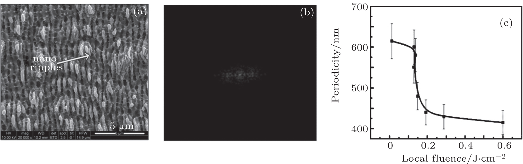
Fast Fourier transform (FFT) has been employed for all fluences in order to measure the variation in periodicity of nano ripples on irradiated Ti surface in O 2 ambient. The enlarged SEM view of nano-ripple formation of Fig. 3(a) shown in Fig. 4(a) , figure 4(b) corresponds to a 2D-FFT image, and figure 4(c) shows the variation in periodicity of nano-LIPSS for various local fluences. The value of periodicity of ripples reduces monotonically from 640 nm to 410 nm, with the increase of local fluence from 0.01 to 0.6 J·cm −2 .

Fig. 4. (a) Magnified view of nano-LIPSS formation of Fig. 3(a) . (b) Two-dimensional fast Fourier transform (FFT) spectra of Fig. 3(a) , and (c) variation in periodicity of nano-LIPSS for various local fluences using FFT after ablation of Ti in O 2 by 100 pulses of fsec laser at wavelength of 800 nm, pulse duration of 30 fsec and repetition rate of 1 kHz

It is found that the environments (vacuum & O 2 ) play a significant role for the growth and periodicity of LIPSS. In the case of a vacuum, the periodicity of ripples varies from 700 to 490 nm, whereas in the case of O 2 , the periodicity varies from 640 to 410 nm. This shows that comparatively fine ripples with slightly less periodicity are formed in the O 2 environment as compared to the vacuum condition. A possible explanation for this fact are confinement effects of O 2 (at a pressure of 133 mbar), which prevents the free expansion of the plume and random movement of ejected material during laser ablation and serves for the fixation of surface waves, in a well defined manner. [ 20 ] This confinement can induce more energy and pressure [ 22 ] as compared to a vacuum and consequently, fine nanoripples with smaller periodicity are grown, which is also compatible with the results presented in Figs. 2 and 4 .

3.2. Quantitative analysis
3.2.1. Ablation threshold and incubation factor

The ablation threshold fluence and incubation factor are important considerations to understand the origin of ablation, when a laser interacts with a material. In order to determine the ablation threshold and the incubation factor, the Ti targets were exposed to single and 100 laser shots. The irradiation was performed under a vacuum and O 2 environment for different pulse energies. The threshold fluence and the incubation factors were then derived from the SEM images of the exposed targets.

Figures 5(a) 5(d) show the variation in the squared spot diameter ( D 2 ) as a function of log (ln) of the pulse energy for single (Figs. 5(a) and 5(c) ) and 100 pulses (Figs. 5(b) and 5(d) ) in both environments. The spot diameter was measured by using SEM images for single and multiple (100) pulse experiments. The focused beam spot size ( ω f ) was determined from the slope of the linear fit (Fig. 5 ). The threshold energy ( E th ) was determined by extrapolating the D 2 to zero. The ablation threshold fluence was calculated by using the following equation: [ 23 ]

Fig. 5. Plot of squared spot diameter ( D 2 ) versus the logarithm of the laser pulse energy under a vacuum (10 −3 mbar) for (a) single pulse, (b) 100 pulses, and in O 2 environment at 133 mbar pressure for (c) single pulse and (d) for100 laser pulses.

The calculated values of the ablation threshold for single and multiple (100) shots are listed in Table 1 . It is clear that the ablation threshold in an O 2 environment is lower than in a vacuum. This is associated with an enhancement of the thermal energy coupling during laser ablation, which is more dominant in a gaseous medium than in a vacuum. [ 21 ] The other possible important factor responsible for the smaller value of the ablation threshold in O 2 is the confinement effect that enhances collisions between the ablated species and the gas molecules. [ 24 ] In a reactive gas, the high temperature and pressure in the plume result in the formation of gas molecule radicals. The reactions between ablated products and these gas radicals promote condensation and induce a faster structure growth, which in turn reduces the ablation threshold. [ 24 ]

Table 1.

Calculated values of ablation threshold fluence and incubation coefficient of Ti, for single and multiple (100) pulses, for both ambient conditions (vacuum and O 2 ) after ablation by fsec laser at a wavelength of 800 nm, pulse duration of 30 fsec and repetition rate of 1 kHz.

.

With increasing the number of laser shots from single to 100 for both environments, a reduction in the ablation threshold is observed. This reduction of the threshold can be attributed to an incubation effect. [ 25 ] In case of metals, the incubation behavior is due to the accumulation of plastic deformation caused by laser-induced thermal stresses. [ 26 ] The incubation coefficient has been evaluated by using the following power law: [ 27 ]

where Φ th ( N ) is the threshold fluence for N laser shots (100 in our case), Φ th (1) is the single-shot ablation threshold fluence, and S is the incubation coefficient. Calculated values of the incubation coefficients are also listed in Table 1 .

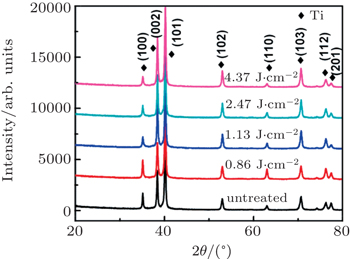
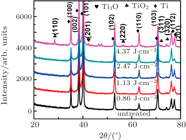
3.3. XRD analysis

In order to explore the structural changes in the ablated Ti, an XRD analysis was performed. Figure 6 shows the x-ray diffractograms of pristine and laser-irradiated Ti exposed to various maximal laser fluences (0.86, 1.13, 2.47, and 4.37 J·cm −2 ) under vacuum conditions. In case of pristine Ti, hexagonal phases of Ti (100), (002), (101), (102), (110), (103), (112), and (201) (Pattern No. 01-089-2959) are identified. The XRD patterns of the irradiated Ti do not show formation of new phases, which indicates that residual thermal stresses were not high enough to create new reflection planes. [ 28 ] A slight decrease in the peak intensity of the (100) plane is observed, which may be due to structural defects caused by irradiation.

Fig. 6. X-ray diffractograms of pristine and laser-irradiated Ti exposed to various fluences of 0.86, 1.13, 2.47, and 4.37 J·cm −2 under vacuum (10 −3 mbar) conditions.

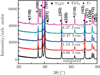
Figure 7 shows the x-ray spectra of the pristine and irradiated Ti exposed for the same conditions but in an O 2 environment. For the low irradiation fluencies, no new phases are observed. However, for the highest maximal fluence, i.e., 4.37 J·cm −2 , several new phases of oxides TiO 2 (110), Ti 3 O (201), TiO 2 (220), TiO 2 (311), TiO 2 (320) are identified. For maximal fluence, melting of the target is maximal and ionization of the ambient gas is very high, which increases the reaction rate between the molten layers of Ti and atomic oxygen. This reaction during the resolidification causes the formation of several new phases of oxides of Ti. The diffusion of reactive gas atoms to interstitial sites can be clearly observed for this fluence. [ 29 ] The presence of O 2 is also confirmed by EDS analysis (Table 2 ).

Fig. 7. X-ray diffractograms of pristine and laser-irradiated Ti exposed to various fluences of 0.86, 1.13, 2.47, and 4.37 J·cm −2 in ambient environment of O 2 at 133 mbar pressure.
Table 2.

An EDS analysis of the unirradiated and fsec laser-irradiated targets of Ti, for the maximum value of fluence (4.37 J·cm −2 ) under a vacuum (10 −3 mbar) and in an O 2 environment at a pressure of 133 mbar for 100 pulses of fsec laser.

.
3.4. EDS analysis

A chemical analysis of the pristine and fsec laser irradiated Ti targets at a maximal laser fluence of 4.37 J·cm −2 under vacuum conditions and in the presence of O 2 at 133 mbar pressure is shown in Table 2 . A percentage error of about ±5% can be assumed for all tabular data. The untreated target of Ti consists of 94% Ti and 6% Al. After irradiation under vacuum conditions, the Al content reduces to 2% with the increased Ti content up to 98%. Whereas, during irradiation in an O 2 environment, 15% content of oxygen is found. The recoil pressure of laser-induced plasma enhances the diffusion of reactive gas atoms to the interstitial sites due to the adsorption of atomic oxygen. [ 29 , 30 ] During laser irradiation, the molecular O 2 dissociates into the atomic O and the probability of diffusion of O is much stronger as compared to O 2 . Therefore, the irradiated targets exhibit a larger oxygen content.

4. Conclusions

Ultrafast pulsed laser interaction with Ti leads to the formation of various kinds of morphological features including self-organized micro and nano-scale LIPSS, conical micro structures and cavities. Both experimental as well as FFT d -spacing calculations show the strong dependence of periodicity of nanoripples on the laser fluence as well as on the ambient environment. The periodicity of LIPSS is shifted to lower values for an O 2 anvironment as compared to vacuum conditions. It is also found that the value of ablation threshold fluence for Ti is higher under vacuum conditions as compared to that in an O 2 environment. The presence of residual stresses is confirmed by peak shifting for the vacuum environment. However, in case of treatment in an O 2 environment the development of new phases (oxides of Ti) along with presence of stresses is observed. EDS analysis exhibits that after irradiation under a vacuum, the percentage of impurity element (Al) has been reduced for both environments. The irradiation in an O 2 environment reveals a concentration (diffusion) of 15% oxygen.

Reference
1 Miyaji G Miyazaki K 2013 Appl. Phys. Lett. 103 071910
2 Hashida M Okamuro K Miyasaka Y Ikuta Y Tokita S Sakabe S 2010 Phys. Rev. B 82 165417
3 Ionin A A Kudryashov S I Makarov S V Seleznev L V Sinitsyn D V Ligachev A E Golosov E V Kolobov Y R 2013 Laser Phys. Lett. 10 056004
4 Lavisse L Jouvard J M Gallien J P Berger P Grevey D Naudy Ph 2007 Appl. Surf. Sci. 254 91
5 Hashida M Sakabe S Tokita S Namba S Okamuro K 2009 Phys. Rev B 79 033409
6 Koter R Bonse J Hartelt M Spaltmann D Pentzien S Höhm S Rosenfeld A Krüger J 2014 App. Surf. Sci. 302 286
7 Oliveira V Ausset S Vilar R 2009 Appl. Surf. Sci. 255 755
8 Nayak B K Gupta M C Kolasinski K W 2008 Appl. Phys. A 90 39
9 Sipe J E Young J F Preston J S Van Driel H M 1983 Phys. Rev. B 27 1141
10 Valette S Bandoki P B Benayoun S Audouard E 2013 Appl. Surf. Sci. 270 197
11 Ikuta Y Hashida M Miyasaka Y Tokita S Sakabe S 2013 App. Phys. Lett. 102 17410
12 Vorobyev A Y Guo C 2008 J. Appl. Phys. 103 034903
13 Bonse J Hohm S Rosenfeld A Kruger J 2013 Appl. Phys. A 110 54
14 Kruger J Bonse J 2010 J. Appl. Phys. 108 034903
15 Huang M Zhao F Cheng Y Xu N Xu Z 2009 ACS Nano 3 406
16 Guan Y C Zhou W Li Z L Zheng H Y Lim G C Hong M H 2013 Appl. Phys. A 115 13
17 Umm-i-Kalsoom Bashir S Ali N 2013 Surf. Coat. Technol. 235 297
18 Sohn I B Kim S H Jeong S 2011 Appl. Surf. Sci. 103 105
19 Kuraika M M Dojcinovic I P Puric J 2010 Vacuum 85 596
20 Baba M Ganeev R A Ozaki T Kuroda H 2010 J. Opt. Soc. Am. B 27 1077
21 Vorobyev A Y Guo C 2007 J. Phys. Conf. Ser. 59 41
22 Bindhu C Harilal S Tillack M Najmabadi F Gaeris A 2003 J. Appl. Phys. 93 2380
23 Van Popta A C Kirkwood S E Tsui Y Y Fedosejevs R 2005 Appl. Phys. A 81 729
24 Pereira A Cros A Delaporte P Georgiou S Manousaki A Marine W Sentis M 2004 Appl. Phys. A 79 1433
25 Rafique M S Bashir S Husinsky W Hobro A Lendl B 2012 Appl. Surf. Sci. 258 3178
26 Koumvakalis N Lee C S Bass M 1982 Appl. Phys. Lett. 41 625
27 Mannion P T Magee J Coyne E ’Connor G M Glynn T J 2004 Appl. Surf. Sci. 233 275
28 Baboo M Sharma K Saxena N S 2011 Nucl. Instr. & Meth. 269 2479
29 Sicard E Thomann A L Leborgne C B Vivien C Hermann J Vignolle C A Andreazza P Meneau C 1997 Surf. Coat. Technol. 97 44
30 Biao Y Wang G Yong Y Wang Z Peng X 2015 Acta Phys. Sin. 6 026602 (in Chinese)