Project supported by the National Key R&D Program of China (Grant No. 2016YFA0301700), the National Natural Science Foundation of China (Grant Nos. 11674300, 61674132, 11575172, and 11625419), and the Fundamental Research Fund for the Central Universities, China.
Project supported by the National Key R&D Program of China (Grant No. 2016YFA0301700), the National Natural Science Foundation of China (Grant Nos. 11674300, 61674132, 11575172, and 11625419), and the Fundamental Research Fund for the Central Universities, China.
† Corresponding author. E-mail:
Project supported by the National Key R&D Program of China (Grant No. 2016YFA0301700), the National Natural Science Foundation of China (Grant Nos. 11674300, 61674132, 11575172, and 11625419), and the Fundamental Research Fund for the Central Universities, China.
Thirty years of effort in semiconductor quantum dots has resulted in significant developments in the control of spin quantum bits (qubits). The natural two-energy level of spin states provides a path toward quantum information processing. In particular, the experimental implementation of spin control with high fidelity provides the possibility of realizing quantum computing. In this review, we will discuss the basic elements of spin qubits in semiconductor quantum dots and summarize some important experiments that have demonstrated the direct manipulation of spin states with an applied electric field and/or magnetic field. The results of recent experiments on spin qubits reveal a bright future for quantum information processing.
The field of quantum information technology is rapidly developing, and scientists are actively trying to implement efficient quantum gates in a variety of systems, particularly in solid-state systems. Manipulating spin states in semiconductors is one of the most important avenues for constructing a quantum gate, considering that electron spin is a reliable carrier of processed information and can be manipulated arbitrarily with a relatively high reliability. The realization of electrical or magnetic control of spin states in semiconductors has provided compelling evidence of the potential computing applications.
Nearly three decades ago, research was initiated on quantum dots which were known as artificial atoms.[1–3] In the beginning, the exact number of electrons in the dots was uncertain. The precise number was eventually confirmed in 1996.[4] Shortly thereafter, the proposal for a quantum computer architecture using electron spins in quantum dots (QDs) was developed. Later, the precise control of spin states was demonstrated via electrical methods.[5] After a series of successful experiments, scientists were able to characterize these systems based on several parameters including T1 (relaxation time) and T2 (coherence time). At the same time, the Pauli spin blockade phenomenon was discovered in double quantum dots (DQDs).[6] At present, one of the spin-to-charge conversion strategies based on this phenomenon is widely used to initialize and readout the spin states of electrons in QDs.[7]
The first demonstration of electrically controlled single-spin qubits was reported in 2005.[8] Several years later, two-spin qubits were realized as well as the entanglement of the encoded spin states in GaAs QDs.[9,10] In addition, single-spin qubits and two-spin qubits are implemented in silicon metal–oxide semiconductor (Si MOS)[11–13] and Si/SiGe systems.[14–18] Currently, it is possible to achieve a gate fidelity of 90% for different systems and occasionally, even higher than 99%.[19–21] However, further research is still required to improve the coherence time and fidelity.
This section summarizes the status of research in spin qubits in a semiconductor quantum dot. Section
A quantum dot is a kind of ‘artificial atom.’ It can be filled with electrons (or holes) confined by a certain metal gates structure. The dot is coupled with reservoirs via tunnel barriers and can be detected by applying a current and/or voltage. Also, it is capacitively coupled to gates. By changing the gate voltage, the electrostatic potential can be tuned, and properties of the dots can be controlled. The structures of typical lateral and vertical quantum dots are shown in Figs.
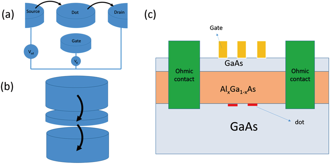 | Fig. 1. (color online) Schematic diagrams of (a) lateral dot and (b) vertical dot, (c) vertical dots fabricated on a GaAs heterostructure. |
The initial focus of the application of quantum dots is for device fabrication on GaAs/AlGaAs heterostructures.[19] In addition to the rapid improvement in technology, high mobility GaAs/AlGaAs heterostructures, Si/SiGe heterostructures,[20–22] Si-MOS,[23–25] graphene,[26–30] and other novel materials[31–36] have also been employed as host materials. It should also be noted that the research focus has transitioned from doped heterostructures to undoped heterostructures,[37–41] since the coherence of spin states is affected by the dopants around the electrons. Nuclear spin plays an important role in the coherence of spin states. At present, purified silicon is regarded as an excellent candidate for spin qubits due to the absence of nuclear spins.[42,43]
The structure of quantum dots changes significantly. Figure
Taking a double quantum dot as an example, if we ignore the spin of an electron, the charge stability diagram (so-called honeycomb diagram) shown in Fig.
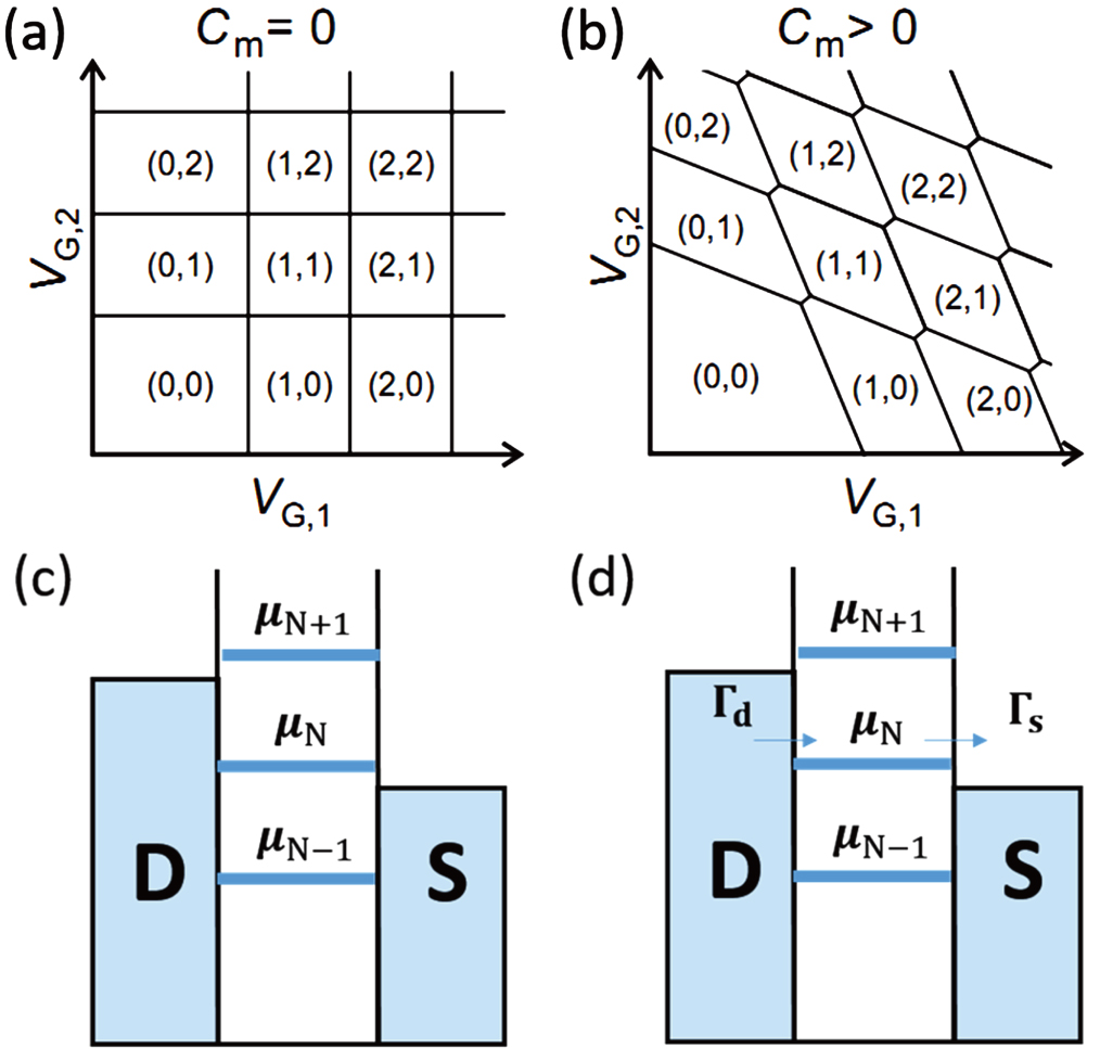 | Fig. 2. (color online) Charge stability diagram of double quantum dots acquired by scanning VG,1, VG,2. (a) Uncoupled and (b) coupled quantum dots can be transformed reversibly into each other by tuning Cm. Cm is the cross capacitance between the dots. The lines in the diagram are the current signals while sweeping the voltage. (c) Discrete energy level of quantum dots (orbital states). (d) An electron can tunnel in (or out) of the dot with a rate Γs (or Γd). Panels (a) and (b) are from Ref. [48]. |
Two effects dominate the electronic properties of quantum dots. One is the Coulomb repulsion between the electrons in the dots, which results in additional energy cost for adding one more electron. This leads to a Coulomb blockade in quantum dots. Another effect is the confinement of dots that leads to the discrete energy spectrum. As shown in Fig.
To understand these properties more clearly, it is necessary to investigate the dots with an appropriate measurement method. There are two traditional ways to obtain information. They include dc transport and charge sensing including quantum point contact (QPC) transport measurement and QPC modulation measurement.
Transport measurement is the most direct method to reproduce a charge stability diagram. In this process, a dc bias and ammeters are directly linked to reservoirs of the double quantum dots (source and drain). Using the dc transport signal, IDot, a triangle-shaped stability diagram (Fig.
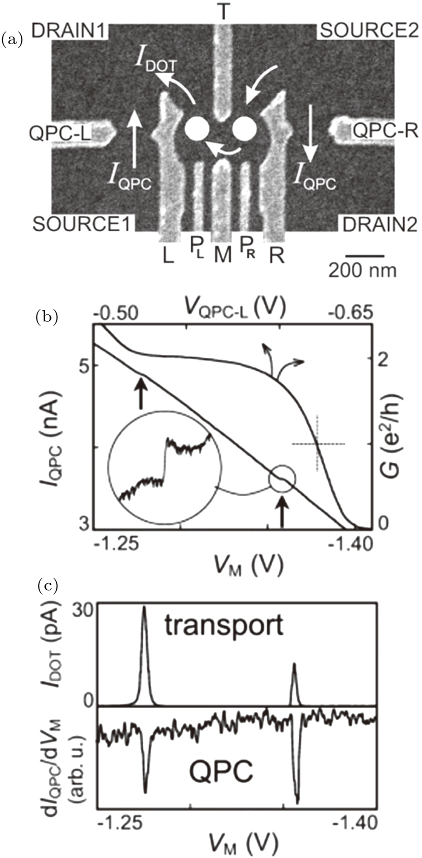 | Fig. 3. (a) Measurement setup for transport and charge sensing. (b) The upper right curve is the QPC conductance versus the QPC gate voltage while the cross indicates the highly sensitive position. The lower left one is the transport signal of the QPC versus gate voltage VM. (c) The upper curve represents the transport signal of the double quantum dots, and the lower one indicates the modulation signal of the QPC. The figure is from Ref. [53]. |
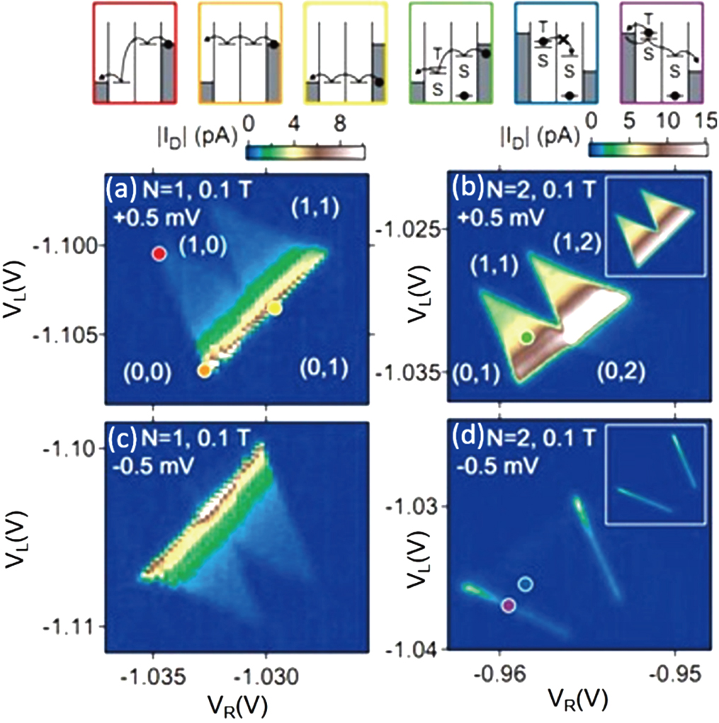 | Fig. 4. (color online) The dc transport measured current by sweeping VR and VL with a (a), (b) positive bias and (c), (d) negative bias. (a), (c) In the one-electron regime, no spin blockade phenomenon is observed, (b), (d) while it is obvious in the two-electron regime. The figure comes from Ref. [59]. |
In addition to transport measurement, there is another method called charge sensing.[54] Superior to standard transport measurement, charge sensing techniques can be used to confirm the number of electrons in single[55] or double quantum dots[53] and to extract some key parameters such as detuning ε and inter-dot coupling 2t.[56–61] In addition, due to the high sensitivity of charge sensors, charge sensing can be used in the absence of a transport signal or for the devices with only one reservoir.[62]
A charge sensor is formed by integrating the QPC beside the quantum dots. In Fig.
It is notable that charge sensing greatly depends on the tunneling rates (Γ). If the tunneling time (1/Γ) is much longer than the measurement time, no signal can be detected. In this case, the change of the electron number cannot be observed while sweeping the gate voltage. On the other hand, this phenomenon can be used to detect the tunneling time by adding short gate voltage pulses which draw electrons in and out. If the gate pulse amplitude is suitable, it can change the electrochemical potential and control the electron number to fluctuate between N and N − 1. Monitoring the average current of the dot electron versus the length of the gate pulse yields information on the tunneling time. When the pulse length is comparable to the tunneling time, the average current of the electrons is sensitive to the change of the tunneling rate. So it can be used to measure the charge dynamics in GaAs quantum dots.[61] It has also been used to measure the spin lifetime of a single electron in Si/SiGe[57,74] and Si-MOS quantum dots.[75]
In addition, two pulses simultaneously added to different gates are used to detect the spin states using a charge sensing technique.[76,77] Finally, improved readout of the spin states mediated by a metastable charge state has been developed, which aids the signal enhancement.[78,79]
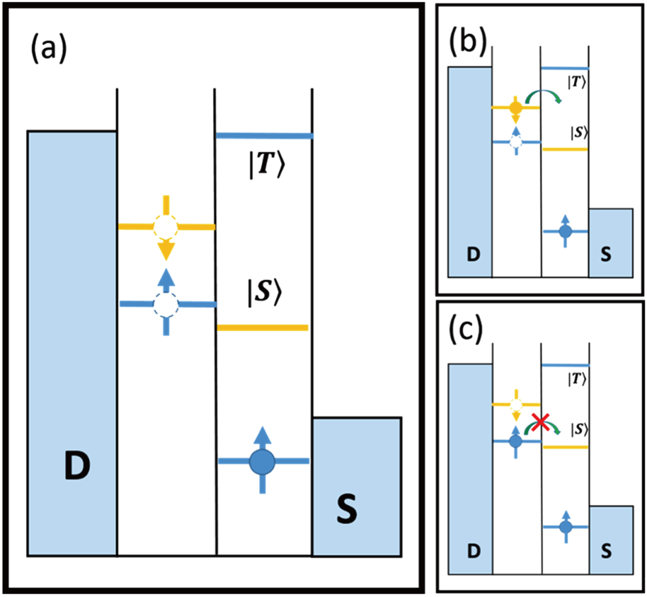
The Pauli spin blockade (PSB) plays an important role in spin dynamics in quantum dots as indicated by the current suppression. The key point is that one orbital state can only be occupied by two electrons with different spin (so-called Pauli exclusion principle). As illustrated in Fig. 
On the contrary, for a positive bias, charge transfer takes place in the sequence (0, 1)→(0, 2)→(1, 1)→(0, 1). The first electron in the right dot is either spin-up or spin-down, and the second electron with an opposite spin direction can tunnel through the right dot, leading to an observable current. This is because the orbital states of each dot in the (1,1) regime are different and the splitting between S(1, 1) and T (1, 1) is comparatively small in the absence of the Pauli exclusion principle.
To clarify current suppression, a typical situation (negative bias) is considered. With an appropriate gate voltage, the (1, 1) regime can be reached. In this regime, each dot is occupied by one electron. Assuming a spin-up electron in the right dot is prepared as shown in Fig.
The first PSB of quantum dots was observed in an experiment on vertical double quantum dots[6] and then in lateral quantum dots.[59] Mostly, this spin-to-charge phenomenon occurs in a two-electron regime, but it has been discussed in a three-electron regime as well.[80]
Due to the tiny magnetic moment of the electron spin, it is difficult to measure the spin state directly. Thus, a spin-to-charge conversion is needed to distinguish a single spin. Over the course of numerous experiments, two methods have been utilized for the readout stage. One is the energy selective readout (E-RO), where the energy difference between the different spin states should be large enough to distinguish a single spin.[7] The other is tunneling rate selective readout (TR-RO).[81] By exploiting the different tunneling rates between two spin states, spin-to-charge conversion is achieved. These two approaches are both important for possible applications in experiments. In both circumstances, the readout fidelities are above 99%.[82] Such strategies are not only suitable for a single spin, but also for two-spin states. Later, spin-state detection of two individual electrons is demonstrated using two independent QPC detectors at the same time.[83]
The first energy selective readout experiment was demonstrated in 2004.[7] As previously indicated, QPC works as an electrometer. When Zeeman splitting is much larger than the energy level broadening, E-RO can be achieved. In Fig.
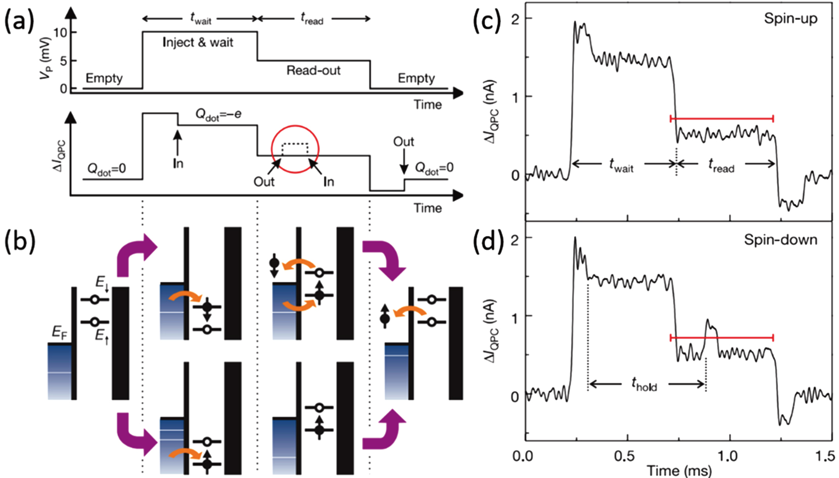 | Fig. 6. (color online) Schematic diagrams of the E-RO single-shot readout progress. (a) The upper panel shows the gate voltage pulse, which consists of three steps: empty, inject & wait, and readout. The lower panel shows the response of the QPC signals. The dashed line represents the signal when spin-down is injected in. (b) Energy diagrams for spin-up and spin-down states for the different situations during the three pulse steps. The upper panel is a spin-down injected diagram while the lower one is spin-up injected. Panels (c) and (d) represent the experimental result of a single-shot readout of an electron spin for two different types of spin states: the upper panel corresponds to a spin-up electron and the lower panel is a spin-down electron. The figure comes from Ref. [7]. |
The method mentioned here depends on the difference of the tunneling rates of the different spin states. The first demonstration of this technique was an experiment for the singlet state (|S〉) and the triplet state (|T0〉).[81] Similar to the E-RO method, a gate pulse is needed to realize the three steps of measurement. Here we assume that the tunneling rate ΓT from the |T〉 state to the reservoir is much larger than ΓS from the |S〉 state. For dots with more than two electrons, it is possible to acquire different tunneling rates because the triplet state is asymmetric and the wave function of the triplet state is more extended than that of the singlet state, leading to a larger overlap with the reservoir.
Like E-RO, TR-RO also starts with the empty stage where no electron occupies the dot as shown in Fig. 
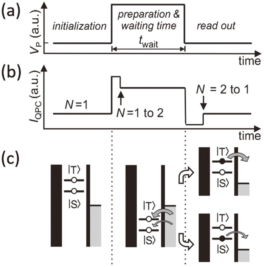 | Fig. 7. (color online) Diagrams of single-shot readout with TR-RO. (a) Shape of gate pulses applied to the gate to control the measurement. (b) Response of QPC signals corresponding to the pulses. (c) Energy diagram of the three steps of the spin-to-charge conversion. The figure comes from Ref. [81]. |
A two-level system can be encoded as a qubit. We can describe a qubit on a Bloch sphere. In Fig.
 |
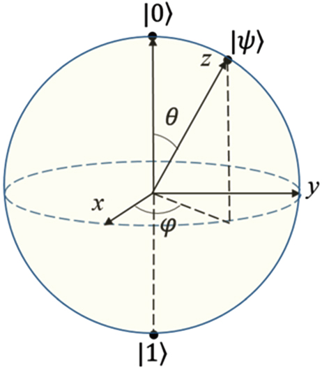 | Fig. 8. (color online) Bloch sphere corresponding to the state of an electron spin qubit. Any state |ψ〉 is a superposition state of |0〉 and |1〉 represented as |ψ〉 = cos(θ/2) |0〉 + eiφ sin (θ/2)|1〉. |
In quantum dot systems, one can encode qubits on both the charge states and the spin states. However, noise disturbance severely limits the coherence of charge states, compared to spin states. There are several types of spin qubits determined by different encoding methods. Loss–DiVincenzo qubits (LD qubits)[10–12,17,84] and singlet-triplet qubits (ST qubits)[8,9] are primarily investigated. Usually, the basis states for a LD qubit are two independent spin states without entanglement, while that for ST qubits are the superposition of states defined as 

In quantum dot systems, the spin states are affected by the environment.[92] Spin–orbit interaction is one of the dominant factors. Usually, this effect is treated as a small perturbation as long as the size of the dot is much smaller than the spin–orbit length lSO. In the case of GaAs (zinc-blend structure), it is suitable to focus on the linear part of the D’yakonov–Perel mechanism[93] although a spin may flip via the Elliot–Yafet mechanism[94] or the Bir–Aronov–Pikus mechanism.[95] The linear Hamiltonian is given by
 |
Nuclear-spin induced hyperfine interaction results in some consequences.[6] Leakage current of the Pauli spin blockade regime is one of these consequences which has been experimentally demonstrated.[97,98] Besides, it has been proved that the electron spin could be flipped via hyperfine interaction.[8]
As previously indicated, the spin states can be represented by any point on the Bloch sphere, and |ψ〉 = α|0〉 + β|1〉 could be written as |ψ〉 = cos (θ/2)|0〉 + eiϕ sin (θ/2 |1〉, where θ is the probability coefficient of the state and ϕ is the phase of the qubit. The spin state could evolve to another arbitrary state after a unitary operation U, which can be recognized as an Euler rotation. Any Euler rotation around x, y, or z is written as R(θ) = exp(−iθσ/2), where σ is any one of the Pauli spin matrices and θ is the angle of rotation. For example, X = exp(−iπσx/2) is the rotation around x, analogous to the classical NOT gate from |0〉 to |1〉. Similarly, Z is the rotation of a spin state around the z-axis and is related to the behavior of an electron spin under a static magnetic field. The system is described by the Hamiltonian H = Ezσz/2, Ez = ħωz is the Zeeman energy. This implies that the static magnetic field (Bz) drives an electron spin rotating around the z-axis at the Larmor frequency ωz. A rotation around the x-axis (or an axis in the x–y plane) and another rotation around the z-axis make up the universal single spin operation.
There are several methods for achieving this spin operation, which are divided into two categories. They are electron spin resonance (ESR) and electric dipole spin resonance (EDSR), and they follow different mechanisms. For ESR, spin operations are achieved by controlling an alternating magnetic field while the EDSR is manipulated completely by electrical means. Several experiments will be discussed in detail to clarify the spin resonance dynamics.
Driven coherent rotation of a single spin has been realized in several solid systems using electron spin resonance (ESR).[99–101] It was proposed by Engel and Loss in a single quantum dot,[102,103] but was realized in GaAs double quantum dots. The first ESR experiment in quantum dots was demonstrated by Koppens et al.[84] Later, it was also demonstrated in a single dot in Si-MOS.[11] In the ESR technique, an oscillating magnetic field BAC with an angular frequency ω along the x-axis and a static magnetic field Bz are applied along the z-axis. BAC is used to achieve spin-flip while Bz induces the Zeeman energy Ez = gμBBz where μB is the Bohr magneton and g is the electron g-factor. The rotation induced by Bz is described as the motion in a coordinate system rotating around the z-axis with rotating frequency ωz = gμBBz/ħ, and the spin state becomes |ψ〉rot = exp(iωztσz/2)|ψ〉. Assuming BAC = xBAC cos (ωt + φ), we can obtain the Hamiltonian
 |
When the Hamiltonian is reduced in the rotating frame followed by the rotating wave approximation, we have
 |

In the experiment, double quantum dots are tuned to a spin blockade regime where each dot is occupied by one electron. Due to the Zeeman energy, triplet states split into T0, T−, and T+ states. Considering the lowest two energy states, the S and T+ as shown in Fig.
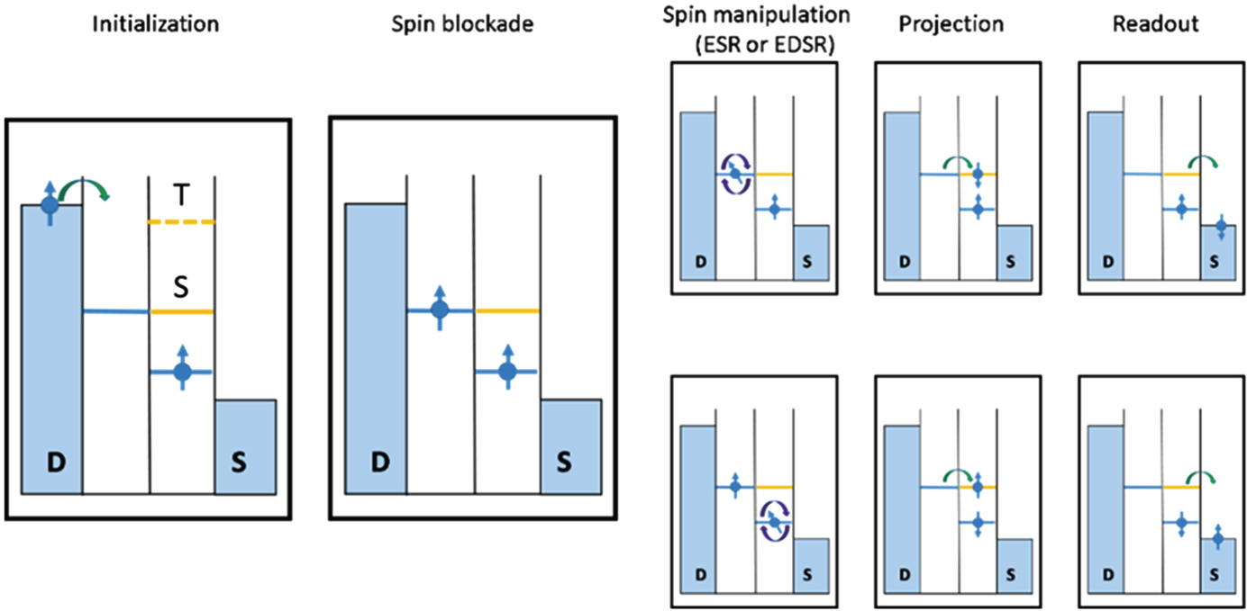 | Fig. 9. (color online) Schematic diagram of the energy level during the ESR or EDSR measurement. It consists of initialization, spin blockade, spin manipulation, projection, and readout. Spin-flip is achieved in the spin manipulation step by hyperfine interaction,[8,104] spin–orbit interaction,[105] inhomogeneous magnetic field,[106] and g-factor tensor modulation.[107] |
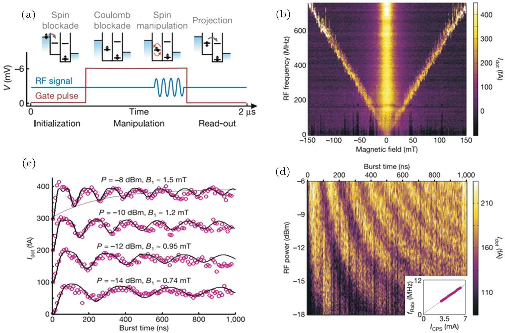 | Fig. 10. (color online) (a) Sequences of pulse and microwaves used to control electron spin. (b) Measured transport current of the dots by sweeping the static magnetic field and RF burst frequency. (c) Coherent single spin rotation as a function of the RF burst time. (d) Rabi oscillation of the ESR experiment. The inset of (d) shows evidence of Rabi frequency dependence on RF power. The figure comes from Ref. [84]. |
In Fig. 

To overcome the disadvantages of ESR, electric dipole spin resonance (EDSR) was theoretically proposed with a spin–orbit interaction (SOI)[108] and an inhomogeneous magnetic field,[109] as the medium to couple the electric field to the electron spin while an ac magnetic field couples to the spin states directly for ESR. In addition, hyperfine interaction[104] and g-tensor modulation resonance (g-TMR)[110] could be the mediating mechanism in the experiment.
Spin–orbit interaction In an EDSR setup, a static magnetic field Bz is applied to the device and an ac driving electric field E(t) is introduced to control spin. In contrast to ESR, EDSR couples orbital states to spin states when SOI works as a mediator. The effective Hamiltonian is given by[108]
 |
 |
 |

 |

 |
In the first EDSR experiment,[105] an ac electric field E(t) and Bz are along the [110] direction where the SOI is much more pronounced than the other directions. As shown in Fig.
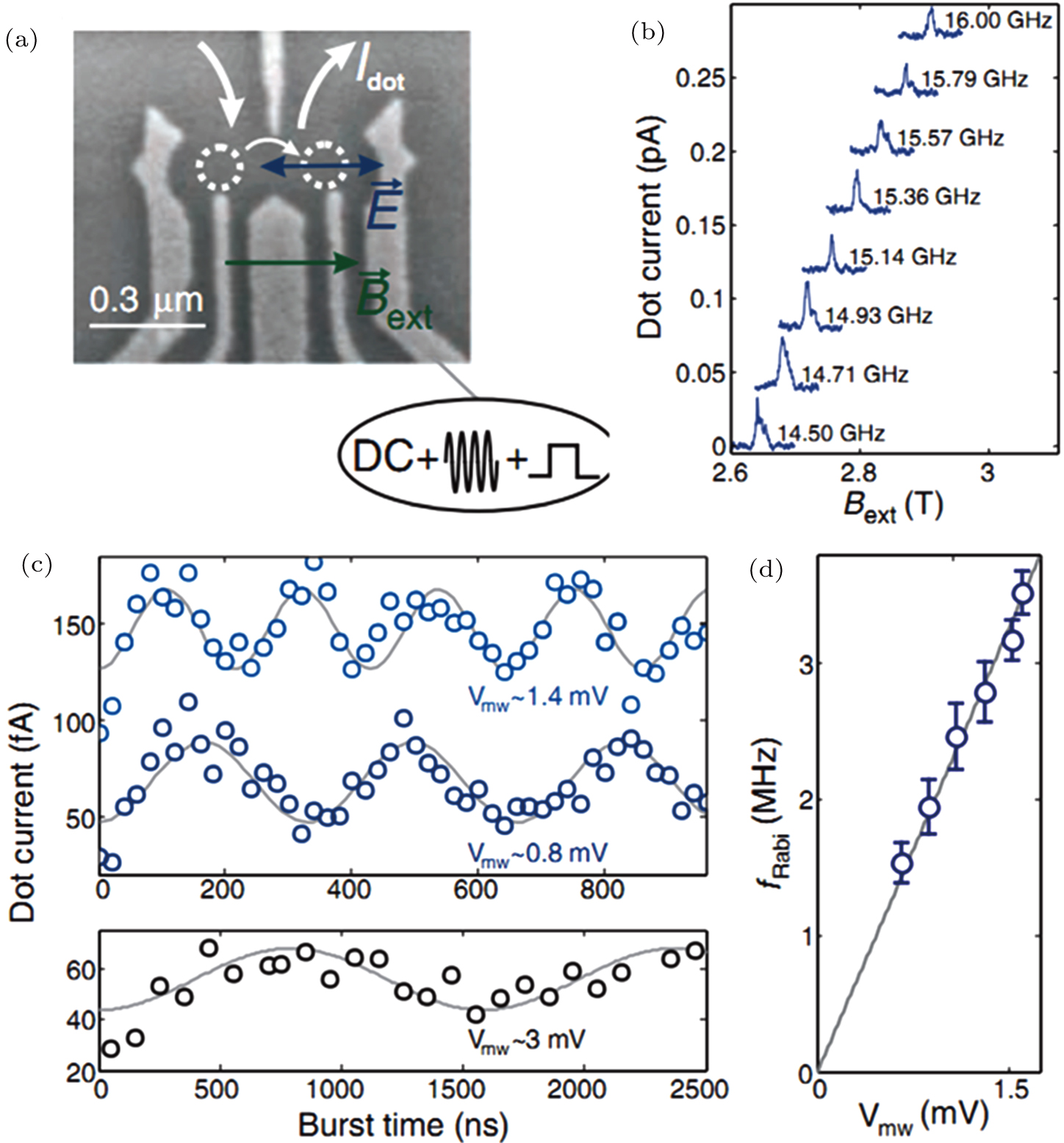 | Fig. 11. (color online) (a) Scanning electron micrograph of the GaAs double quantum dots. The blue arrow indicates the electric field and the green arrow is the direction of the static magnetic field. (b) Resonance of spin-flip by changing the amplitude of the magnetic field and the RF frequency. (c) Rabi oscillation of the EDSR experiment. The period changes along with the amplitude of the microwave. (d) Rabi frequency as a function of amplitude of the microwave (the square root of MW power). The figure comes from Ref. [105]. |
Inhomogeneous magnetic field We can assume that the static magnetic field B0 is applied in the x-direction, and the inhomogeneous field is given by
 |

 |
Figure
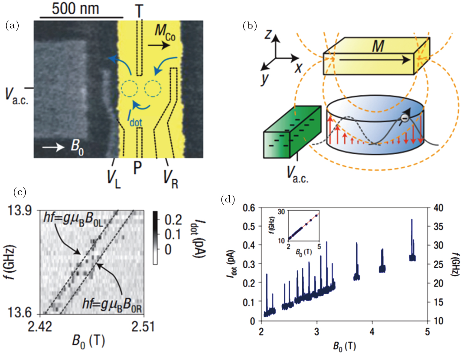 | Fig. 12. (color online) (a) Scanning electron micrograph of the device made on a GaAs heterostructure. The yellow part is the cobalt micro-magnet used to generate a slanting magnetic field. (b) The schematic diagram of the magnetic field generated by the colt magnets. (c) Typical EDSR lines indicating the spin-flip mechanism. Two lines correspond to behaviors in the left dot and the right dot. (d) Position of both resonance peaks in two dots by sweeping the magnetic field. The figure comes from Ref. [106]. |
Tensor modulation resonance (g-TMR) In the experiment, the g-factor is designed to be anisotropic and depends on the voltage so that it is treated as a gate-dependent tensor. Then the Hamiltonian is
 |

 |
 |
All the previously discussed were firstly demonstrated in GaAs systems. By employing the same mechanisms, similar experiments were also performed in other systems, such as Si-MOS,[13] Si/SiGe quantum well,[14,16] and so on.
CNOT, C-phase (control-phase), and swap operation are basic two-qubit operations which are essential for universal control of qubits.[108] The CNOT gate with relative high fidelities are achieved with Si-MOS and SiGe double quantum dots.[12,18] One of the experiments is discussed here to clarify the details.
In the experiment,[17] a DQD is formed on a SiGe heterostructure with an on-chip micro-magnet. As shown in Figs.
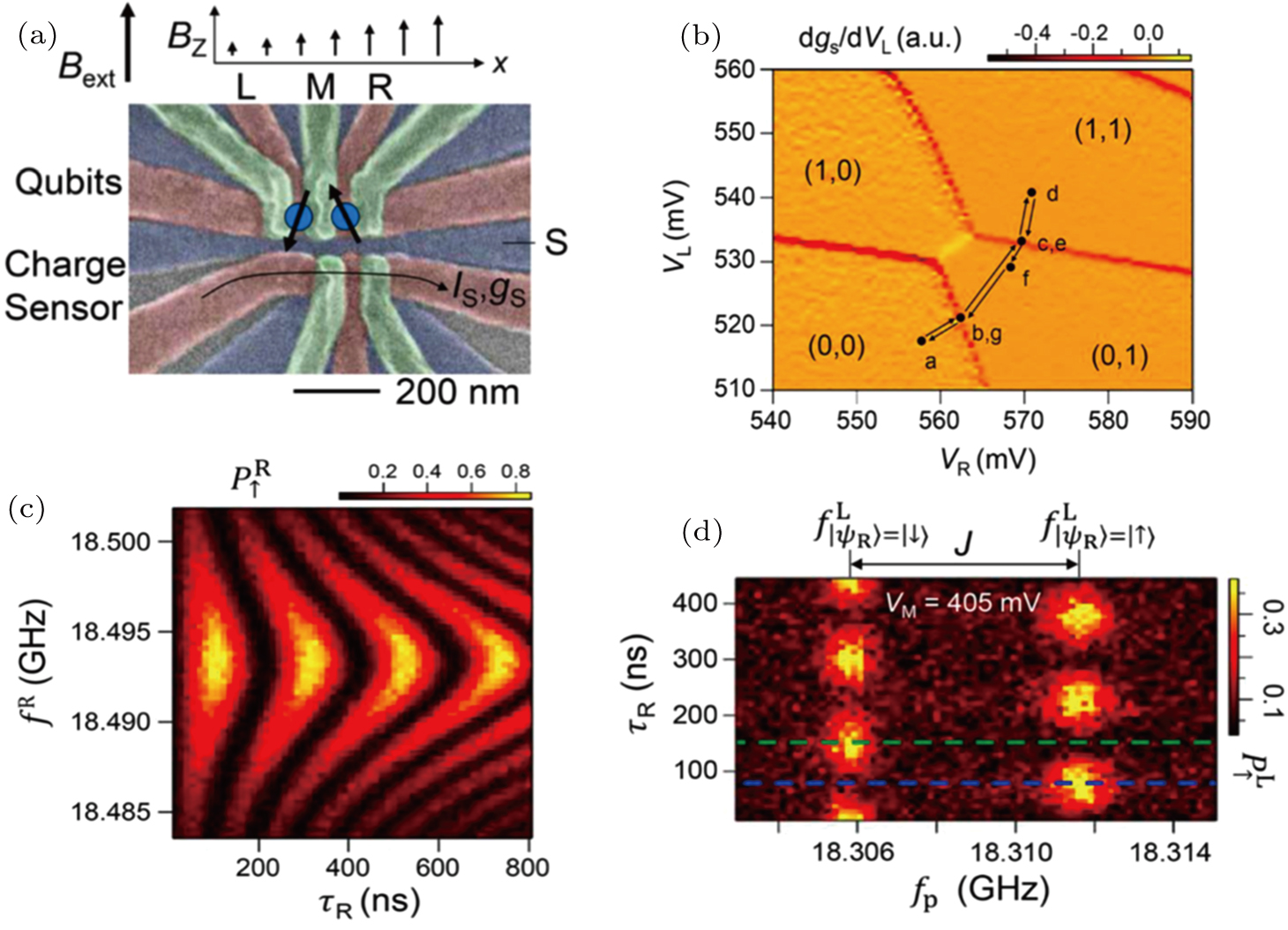 | Fig. 13. (color online) (a) Scanning electron micrograph of the SiGe double quantum dots. (b) Stability diagram of the DQD and schematic of different steps during operations (marked by black points). (c) Rabi oscillations between spin-up and spin-down state of the electron in the right dot. (d) 
|
Considering two-spin operations, the time-dependent Hamiltonian can be written as[113]
 |
 |
 |
 |
 |


Given the eigenvalues of the Hamiltonian, it is reasonable to define the corresponding transition frequencies as
 |
 |
 |
 |


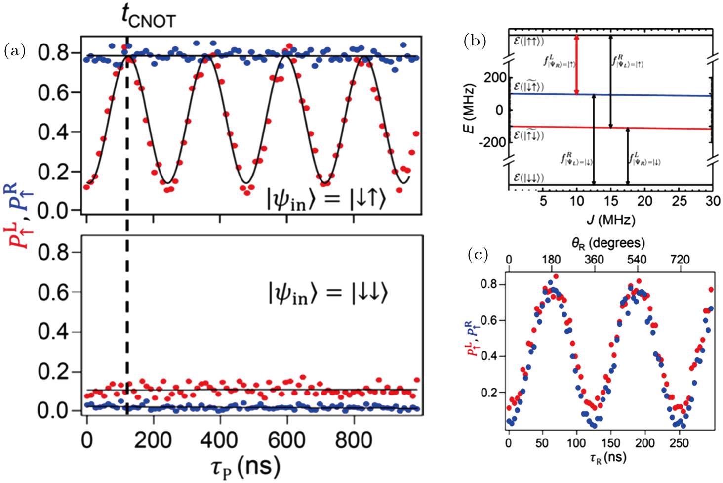 | Fig. 14. (color online) (a) 

|
The CNOT gate is achieved by tuning J and the frequency of the microwave. Using appropriate gate pulses, J can be tuned in a suitable range leading to the difference of the transition frequencies (


Other spin operations, such as x rotation based on two electron spins[10] and a two-qubit operation using two ST qubits in GaAs quantum dots have also been demonstrated.[9] In addition, two-spin qubits in GaAs quantum dot operations in other systems have also been performed. Recently, two-qubits operation in Si-MOS[12] and Si/SiGe[18] systems were demonstrated. Future experiments may focus on inhomogeneous magnetic field to achieve spin manipulation.
Over the past few years, multiple qubits have been demonstrated in quantum dot systems. Further breakthroughs are needed to achieve entanglement of different states, quantum error correction, and so on. The fidelity of qubits is one of their key features, and the highest reported level approaches 90% of the Bell states[18] and 99% of a single-qubit gate.[12,17] In order to realize reliable quantum information processing using quantum dot systems, it is necessary to improve their fidelity and scalability in the next few years.
| [1] | |
| [2] | |
| [3] | |
| [4] | |
| [5] | |
| [6] | |
| [7] | |
| [8] | |
| [9] | |
| [10] | |
| [11] | |
| [12] | |
| [13] | |
| [14] | |
| [15] | |
| [16] | |
| [17] | |
| [18] | |
| [19] | |
| [20] | |
| [21] | |
| [22] | |
| [23] | |
| [24] | |
| [25] | |
| [26] | |
| [27] | |
| [28] | |
| [29] | |
| [30] | |
| [31] | |
| [32] | |
| [33] | |
| [34] | |
| [35] | |
| [36] | |
| [37] | |
| [38] | |
| [39] | |
| [40] | |
| [41] | |
| [42] | |
| [43] | |
| [44] | |
| [45] | |
| [46] | |
| [47] | |
| [48] | |
| [49] | |
| [50] | |
| [51] | |
| [52] | |
| [53] | |
| [54] | |
| [55] | |
| [56] | |
| [57] | |
| [58] | |
| [59] | |
| [60] | |
| [61] | |
| [62] | |
| [63] | |
| [64] | |
| [65] | |
| [66] | |
| [67] | |
| [68] | |
| [69] | |
| [70] | |
| [71] | |
| [72] | |
| [73] | |
| [74] | |
| [75] | |
| [76] | |
| [77] | |
| [78] | |
| [79] | |
| [80] | |
| [81] | |
| [82] | |
| [83] | |
| [84] | |
| [85] | |
| [86] | |
| [87] | |
| [88] | |
| [89] | |
| [90] | |
| [91] | |
| [92] | |
| [93] | |
| [94] | |
| [95] | |
| [96] | |
| [97] | |
| [98] | |
| [99] | |
| [100] | |
| [101] | |
| [102] | |
| [103] | |
| [104] | |
| [105] | |
| [106] | |
| [107] | |
| [108] | |
| [109] | |
| [110] | |
| [111] | |
| [112] | |
| [113] |


