Numerical simulation of modulation to incident laser by submicron to micron surface contaminants on fused silica
Yang Liang 1, 2 , Xiang Xia 1, †, , Miao Xin-Xiang 2, ‡, , Li Li 1 , Yuan Xiao-Dong 2 , Yan Zhong-Hua 1 , Zhou Guo-Rui 2 , Lv Hai-Bing 2 , Zheng Wan-Guo 2 , Zu Xiao-Tao 1
School of Physical Electronics, University of Electronic Science and Technology of China, Chengdu 610054, China
Research Center of Laser Fusion, China Academy of Engineering Physics, Mianyang 621900, China


† Corresponding author. E-mail: xiaxiang@uestc.edu.cn

‡ Corresponding author. E-mail: miaoxinxiang.714@163.com

Project supported by the National Natural Science Foundation of China (Grant No. 61178018) and the Ph.D. Funding Support Program of Education Ministry of China (Grant No. 20110185110007).

Abstract
Abstract

Modulation caused by surface/subsurface contaminants is one of the important factors for laser-induced damage of fused silica. In this work, a three-dimensional finite-difference time-domain (3D-FDTD) method is employed to simulate the electric field intensity distribution in the vicinity of particulate contaminants on fused silica surface. The simulated results reveal that the contaminant on both the input and output surfaces plays an important role in the electric field modulation of the incident laser. The influences of the shape, size, embedded depth, dielectric constant ( ε r ), and the number of contaminant particles on the electric field distribution are discussed in detail. Meanwhile, the corresponding physical mechanism is analyzed theoretically.

1. Introduction

High-peak power lasers have been developed in many fields, including laser-driven inertial confinement fusion (ICF) experiments, material properties at extreme conditions, and laser micromachining. Thousands of optical components including fused silica glass are needed in high-peak power laser systems. [ 1 ] In particular, they serve as lenses, mirrors, vacuum windows, debris shields, etc., for large laser facilities such as National Ignition Facility (NIF) in USA, [ 2 ] Laser MegaJoule (LMJ) in France, [ 3 ] and SG-III laser facility in China. [ 4 ] However, surface/subsurface contaminations of the optical components are inevitable during the assembling and operating processes. Those particles are difficult to remove completely from the optical surface because of the strong adhesion forces for tiny particulates, especially submicron ones. [ 5 , 6 ] Actually, the laser-induced damage in optics due to contaminations has become a major obstacle for its applications. Due to absorption, scattering, and modulation of the contaminants, contamination-enhanced laser-induced optical damage (C-LID) has been proved to be a significant factor in reducing the laser reliability and lifetime. [ 7 ] Furthermore, contaminations will restrict the energy delivered to the target and increase the running cost of the laser systems, particularly at 355 nm. For this reason, it is useful to establish a C-LID model about laser modulation to aid understanding of the damage mechanisms.

The laser-induced damage involves intrinsic and extrinsic damage. The intrinsic damage of the optical material caused by intense laser pulse has been widely studied. [ 8 10 ] In most cases, the damage mechanism is usually attributed to multi-photon ionization, avalanche ionization, and joule heating. The extrinsic damage means the damage of the optical material mainly caused by other factors such as surface contamination, stress, etc. C-LID is an extrinsic damage and there have been some reports about its damage behaviors and mechanisms. For strong absorption contaminants such as metallic particles, the damage threshold is often determined by the thermal stress induced by the heating of the contaminant in the laser beam. The absorbing particles in glass have been studied in detail both experimentally and theoretically. [ 11 14 ] For non-absorbable or weak absorption contaminants, light intensity modulation caused by the surface contaminants plays an important role for laser-induced damage. Génin et al. studied the light intensity distribution behind an obscuration by using Fresnel diffraction theory. The results showed that the intensity modulation is as a function of particle size (10–150 μm), shape and of the distance from the particle. [ 15 ] Mainguy et al. studied the propagation of high-power laser beams when interacting with environmental pollution particles by using CEA-DAM MIRÓ beam propagation code, and concluded that the highest intensification factor is up to about 9 in the downstream propagation for the circular phase particles in the cases of ∼ Φ 150 μm at 3 ω laser and ∼ Φ 400 μm at 1 ω laser. [ 16 ] Previous studies mainly focused on light intensity modulations from the particles with size of about dozens to hundreds of microns. However, little work has contributed to the electric field modulation with the scale ranging from sub-micrometric to micrometric particles. However, a large number of micron even smaller particles exist in the high-peak power laser facilities. [ 17 ]

In this work, the light intensity modulation caused by submicron to micron contamination particles on the input/output surface is numerically calculated with three-dimensional finite difference time domain (3D-FDTD) method. The effect of the shape, size, dielectric constant ( ε r ), and the number of particles on the electric field distribution is simulated and discussed.

2. Model and method

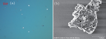
According to the morphology of particulate contaminants on the surface of fused silica observed by an optical microscope and scanning electron microscopy (SEM) (Fig. 1 ), particulate contaminants can be approximated as ellipsoids with a sub-micrometric to micrometric scale. In this work, a 3D model of contaminants is built for particles on both input and output surfaces, as shown in Fig. 2 . In this model, the particles can be described by

where ( x 0 , y 0 , z 0 ) is the center of the ellipsoid; a , b , and c are the semi-axes of ellipsoid along x , y , and z directions, respectively.

Fig. 1. The morphology of the particulate contaminant observed by (a) optical microscope and (b) scanning electron microscopy.
Fig. 2. Schematic illustration of the particulate contaminant: (a) on the input surface, (b) on the output surface of fused silica, a , b , and c are semi-axes of ellipsoid along x , y , and z directions, and h is the depth of particle embedded in the surface.

In general, FDTD method is well applied to calculate the electric field for a scale of wavelength-level. Therefore, this method is appropriate to calculate the electric field caused by the particulate contaminant with a size ranging from submicron to a few microns, and the calculated results are reliable for tiny particles. In this work, Maxwell’s equations are solved by 3D-FDTD method to calculate the electric field intensity distribution in the vicinity of the contaminant. [ 18 ] For simulation, the wavelength of the incidence laser is λ = 355 nm. The simulation region is rectangular gridded with a uniform grid δ = λ /12 = 29.6 nm, and the domain size is 160 δ × 160 δ × 215 δ . The perfectly matched layer (PML) absorbing-boundary condition is utilized in this paper, which is a lossy medium with ultralow reflectance over a broad spectrum and large angles of incidence. [ 18 , 19 ] The thickness of the PML is 21 δ , which is applicable for the total field region. In addition, the 355-nm laser with an amplitude of 1.0 V/m is loaded along the z axis, and the transverse magnetic (TM) wave is considered in this work. The relative dielectric constants of fused silica, air, and the contaminant are 2.25, 1.0, and ε r = 3.8 (besides the relative dielectric constant in Section 3.3), respectively.

3. Results and discussion
3.1. Modulation versus particle shape

In this section, the influence of the flattening of the ellipsoid on the electric field ∣ E ∣ distribution is investigated. The ratio of the semi-axis along y direction to the semi-axis along x direction ( b / a ) is defined as the flattening of the ellipsoid. In order to ensure b / a is the only influencing factor, other parameters should be fixed. The semi-axis of the ellipsoid along x direction is set as a = 4 λ , while b and c change from 1 λ to 5 λ , and the embedded depth is set as h = 0, i.e., the whole particle lies on the surface.

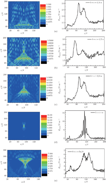
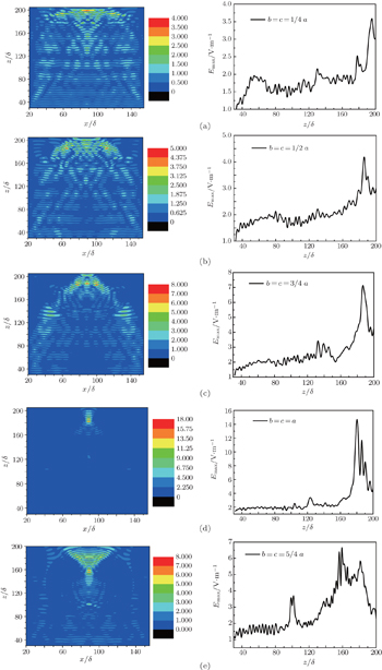
Figures 3 and 4 show the electric field ∣ E ∣ distributions in x z plane ( y = 89 δ ) and the peak electric field ( E max ) along z direction for different flattening of ellipsoid for contaminant on the input and output surfaces. The simulated results reveal that the electric field modulation increases notably with the ratio b / a increasing if b a , and the electric field modulation will decrease if b > a . In addition, the intensity regions mainly appear near to the z axis in all cases, and the intensity regions also appear at the two sides of the z axis when b > a . Figure 5 shows the peak electric field ( E max ) along the x direction. The results show that the electric field is significantly modulated by the particle and the electric field distribution is symmetrical. Particularly, the maximum electric field intensity ( E max ) reaches 14.73 V/m for the spherical particle ( b / a = 1) on the input surface and 15.5 V/m for the spherical particle on the output surface. This phenomenon can be explained as follows. Since the particle is ellipsoid, it is a similar convex lens located at the position of the particle site. The incident laser is focused and scattered by the convex lens. When the focusing and scattering waves overlap with the incident waves, the electric field is intensified as they satisfy the condition of interference to reinforce in the overlap. [ 20 , 21 ] Therefore, the ellipsoid becomes more round, the focusing effect is more obvious, and the electric field intensity modulation is stronger.
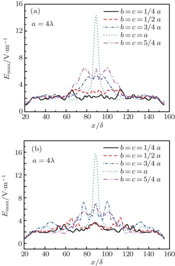
Fig. 3. Electric field ∣ E ∣ distributions in x z plane and peak electric field E max along z direction for different flattening of ellipsoid: (a) a = 4 λ , b = c = λ , (b) a = 4 λ , b = c = 2 λ , (c) a = 4 λ , b = c = 3 λ , (d) a = b = c = 4 λ , and (e) a = 4 λ , b = c = 5 λ for contaminant on the input surface. Left: E in x z plane ( y = 89 δ ), right: E max along z direction.
Fig. 4. Electric field ∣ E ∣ distributions in x z plane are parallel to the incident laser and pass through the center of the ellipsoid for different flattening of the ellipsoid: (a) a = 4 λ , b = c = λ , (b) a = 4 λ , b = c = 2 λ , (c) a = 4 λ , b = c = 3 λ , (d) a = b = c = 4 λ , and (e) a = 4 λ , b = c = 5 λ as contaminant on the output surface. Left: E in x z plane ( y = 89 δ ), right: E max along z direction.
Fig. 5. Peak electric field E max distribution along x direction for different flattening of ellipsoid for the particle (a) on the input surface and (b) on the output surface.

The simulation also reveals that the influences of the contaminant on fused silica optics are different for particles on the input surface and output surface. For the input surface contamination, the maximum electric field appears in the surface or the subsurface of fused silica, as shown in Fig. 3 . The material properties in this zone may be degenerated (local ageing, fragile and even breaking) after the intense field irradiation. Initial damage will appear in these weak zones and induce damage growth at low laser fluence. For the output surface contamination, the maximum electric field does not appear in fused silica but in the top or out of the top of the particle, as shown in Fig. 4 . The air above the surface of fused silica is ionized by the local intense field, and the plasma shock wave is produced after ionization. Therefore, it has a “laser clean” effect, and some contaminants on the output surface will be removed by the shock wave before fused silica is damaged. [ 22 ] Based on the simulated results, it is easy to understand why the laser-induced damage for particles on the output surface is higher than that on the input surface at the same contamination conditions.

3.2. Modulation versus particle size

In order to investigate the influence of particle size on the electric field intensity modulation of the incident laser, we calculated the electric field distribution for the spherical particle with a radius changing from 1 λ to 5 λ for three cases: (i) the whole particle lies on the surface ( h = 0), (ii) half of the particle is embedded in the surface ( h = r ), and (iii) the whole particle is embedded in the surface ( h = 2 r ).

Figure 6 shows the correlation between the maximum electric field intensity E max and the radius of the spherical particle. Figure 6(a) reveals that the E max increases with the radius of the spherical particle increasing when the particle lies on the input surface. In addition, the results also indicate that the maximum of electric field is also related to the depth of the particle embedded in the surface. The less the depth is, the stronger the modulation is for the same particles. Figure 6(b) shows that the maximum of electric field E max varies with the radius of the spherical particle with the particle on the output surface. It increases with the increasing radius just in the case when the whole particle is on the surface ( h = 0). In the cases of h = r and h = 2 r , the maximum of electric field E max fluctuates with the increasing radius. Since the position of the particle embedded in fused silica is different, the interfaces between particles and fused silica/air are different in the three cases. Nevertheless, the incident laser will mainly be scattered and focused at the interface. Therefore, the modulation is different for different embedded depths even though at the same radius. For h = r , the hyposphere is embedded in fused silica and the episphere is exposed to air. As the refractive index of contaminant is larger than those of fused silica and air, the hyposphere has a focusing effect and episphere has a scattering effect. The two effects compete and the variety of modulation intensity is little with the increase of radius. However, for h = 0, since the whole particle is exposed to air, the focusing effect plays an important role. Therefore, the larger the radius is, the stronger the modulation is.

Fig. 6. Maximum electric field E max changing with the radius of the spherical particle as the particle (a) on the input surface and (b) on the output surface.
3.3. Modulation versus relative dielectric constant ε r of particles

In general, various contaminants, e.g., dust, aerosol, metal flakes, cloth threads, etc., exist on the surface of fused silica. Hence, the relative dielectric constant ε r of these contaminants is different. In order to understand the influences of different contaminants on the electric field modulation, it is necessary to discuss the relation between laser modulation and ε r of particulate contaminants.

Figure 7 shows the evolution of maximum electric field E max with ε r of particulate contaminants. The results indicate that the ε r of the particle is one of the important factors for the electric field modulation, which is also related to the shape of the particle. For the ellipsoid particle, the peak of electric field E max is fluctuant with the increasing ε r for any embedded depth of the contaminant. For the spherical particle on the input surface, the E max increases firstly when ε r < 5, and then decreases with the increasing ε r . For the spherical particle on the output surface, the E max increases firstly when ε r < 4, and then decreases with the increasing ε r . The reason can be analyzed as follows. The laser is focused and reflected at the position of the particle. Both focusing and reflecting increase with the relative dielectric constant. However, the focusing effect strengthens the electric field modulation and reflecting effect weakens the electric field modulation. Therefore, these two effects are competing. For the ellipsoid particle, since the focusing and reflecting effects are not obvious, the variety of modulation intensity is little with the increase of the relative dielectric constant. For the spherical particle, both the focusing and reflecting effects are strong. In the low relative dielectric constant case, as the reflection is weak, and the focusing increases with ε r , so the modulation increases with ε r . The maximum E max is the result of focusing much higher than reflection. In the high relative dielectric constant case, the reflection plays a significant role. The incident laser will weaken with the reflection of contaminant, and it heightens with ε r , so the modulation decreases with ε r .

Fig. 7. Variation of E max with the relative dielectric constant ε r of particle for the particle on (a) the input surface and (b) the output surface for different flattening of the ellipsoid.
3.4. Modulation versus the number of particles

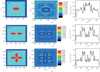
In the actual optical subsurface, a number of particles probably exist in a given domain, so it is necessary to discuss the modulation of the electric field multiple for particles. In this section, we will discuss the influences of one, two, and four particles on the modulation. Here, we just discuss particles on the input surface. All particles are the same ellipsoid, the long semi-axis of the ellipsoid is a = 2 λ , and the short semi-axis of the ellipsoid is b = c = λ . The distance d between two adjacent particles is λ .

Figure 8 reveals the distribution of electric field intensity in x y plane ( z = 53 δ ) and the maximum electric field along x direction for three models. It can be seen that the peak electric field appears in the long axis of the ellipsoid particle, especially at the two ends of the ellipsoid. The electric field intensity modulation does not differ much for two and four particles, but they are slightly higher than that for one particle. In other words, the modulation is not sensitive to the number of particles when the distances between particles are the same.

In summary, the electric field intensity modulation to the incident laser by surface contaminants on fused silica depends on the particle parameters, including the shape, size, embedded depth, dielectric constant ( ε r ), and the number of particulate contaminants. In addition, the modulation on fused silica for particles on the input surface is higher than that on the output surface at the same contamination conditions. In this work, we just considered ellipsoid particles and spherical particles. Actually, the surface contaminants have different shapes and morphologies. The local electric field is usually enhanced by the irregular regions. [ 23 25 ] However, since the high local field caused by the irregular regions is usually not in fused silica but in particle, it has little effects on the distribution of total electric field intensity in fused silica.

Fig. 8. Electric field ∣ E ∣ distribution in x y plane ( z = 53 δ ) and E max along x direction for one (a), two (b), and four (c) particles. Left: model, middle: E in x y plane ( z = 53 δ ), right: E max along x direction.
4. Conclusions

The influence of particulate contaminate on the electric field intensity modulation for different parameters is simulated with 3D-FDTD method. Several conclusions are obtained as follows.

Reference
1 Campbell J H Hawley-Fedder R A Stolz C J Menapace J A Borden M R Whitman P K Yu J Runkel M J Riley M O Feit M D Hackel R P 2004 Proc. SPIE 5341 84
2 Haynam C Wegner P Auerbach J Bowers M Dixit S Erbert G Heestand G Henesian M Hermann M Jancaitis K 2007 Appl. Opt. 46 3276
3 Andre M L 1999 Fusion Eng. Des. 44 43
4 Yu H W Jing F Wei X F Zheng W G Zhang X M Sui Z Li M Hu D X He S B Peng Z 2008 Proc. SPIE 7131 713112
5 Tam A C Leung W P Zapka W Ziemlich W 1992 J. Appl. Phys. 71 3515
6 Sommer S C Stowers I F van Doren D E 2003 J. IEST 46 85
7 Feit M D Rubenchik A M Faux D R Riddle R A Shapiro A B Eder D C Penetrante B M Milam D Genin F Y Kozlowski M R 1997 Proc. SPIE 3047 480
8 Deng H X Zu X T Xiang X Sun K 2010 Phys. Rev. Lett. 105 1136031
9 Stuart B Feit M Herman S Rubenchik A Shore B Perry M 1996 Phys. Rev. B 53 1749
10 Kuzuu N Yoshida K Yoshida H Kamimura T Kamisugi N 1999 Appl. Opt. 38 2510
11 Neauport J Lamaignere L Bercegol H Pilon F Birolleau J C 2005 Opt. Express 13 10163
12 Lighty J S Silcox G D Pershing D W Cundy V A Linz D G 1990 Environmental Science & Technology 24 750
13 Palmier S Garcia S Rullier J L 2008 Opt. Eng. 47 084203
14 Honig J Norton M A Hollingsworth W G Donohue E E Johnson M A 2005 Proc. SPIE 5647 129
15 Génin F Y Feit M D Kozlowski M R Rubenchik A M Salleo A Yoshiyama J 2000 Appl. Opt. 39 3654
16 Mainguy S Tovena-Pecault I Le Garrec B 2005 Proc. SPIE 5991 59910G1
17 Honig J 2004 Opt. Eng. 43 2904
18 Oubre C Nordlander P 2004 J. Phys. Chem. B 108 17740
19 Li L Xiang X Zu X T Yuan X D He S B Jiang X D Zheng W G 2012 Chin. Phys. B 21 044212
20 Bloembergen N 1973 Appl. Opt. 12 661
21 Li L Xiang X Zu X T Wang H J Yuan X D Jiang X D Zheng W G Dai W 2011 Chin. Phys. B 20 074209
22 Ye Y Y Yuan X D Xiang X Dai W Chen M Miao X X Lv H B Wang H J Zheng W G 2011 Opt. Lasers Eng. 49 536
23 Cheng J Chen M J Liao W Wang H J Xiao Y Li M Q 2013 Opt. Express 21 16799
24 Stolz C J Feit M D Pistor T V 2006 Appl. Opt. 45 1594
25 Zhang C L Liu C M Xiang X Wang Z G Li L Yuan X D He S B Zu X T 2012 Acta Phys. Sin. 61 164207 (in Chinese)