†Corresponding author. E-mail: cylin@mail.buct.edu.cn
*Project supported by the Fundamental Research Funds for the Central Universities, China (Grant Nos. JD1517, ZY1349, and 2652014012).
A method of designing broad angular phase retarders in the extreme ultraviolet (EUV) region is presented. The design is based on a standard Levenberg–Marquardt algorithm combined with a common merit function. Using this method, a series of broad angular EUV phase retarders were designed using aperiodic Mo/Si multilayers. At photon energy of 90 eV, broad angular phase retarders with 30°, 60°, and 90° phase retardations have been realized in the angular range of 39°–51°. By analyzing and comparing the performances of the designed broad angular phase retarders, we found that the Mo/Si multilayer with more layers could obtain higher phase retardation in broader angular range when used to design the broad angular phase retarder. Broad angular phase retarders possess lower sensitivity toward changing incident angle compared with the traditional phase retarders designed with transmission periodic multilayers, and can be used for the polarization control of broad angular EUV sources.
Accurate evaluation of the polarization state of the synchrotron radiation, e.g., the extreme ultraviolet (EUV) radiation, is fundamentally important for many scientific research studies such as magnetic circular dichroism (MCD)[1– 3] and Faraday effect.[4, 5] To achieve a complete polarization analysis of the synchrotron radiation, a phase retarder, which can introduce a phase retardation between the two orthogonal (s- and p-polarized) components of the electric field, is necessary.[6, 7] However, in the EUV region, the nature of materials (the closeness of the refractive index and the high absorption index) makes the realization of EUV phase retarders nearly impossible.
In 1990, Kortright and Underwood first predicted the high potential of transmission multilayers as phase retarders in the EUV region.[8] Then, Kortright et al., [9] Nomura et al., [10] and Yamamoto et al.[11] fabricated and characterized EUV phase retarders respectively, and proved the potential of transmission Mo/Si multilayer as EUV phase retarders. After that, the complete polarization analysis of EUV synchrotron radiation was performed by Kmura et al., [12, 13] Schafers et al., [7] and Wang et al.[14] successively with the use of EUV transmission multilayers. In addition, broadband Mo/Si multilayer transmission phase retarders for EUV were also successfully prepared by Wang et al., [15] and used for the polarization analysis of EUV radiation in a broad wavelength range.[16]
However, as predicted by Yamamoto et al.[17] and Kim et al., [18] the phase retardation of the EUV multilayer phase retarders always exhibits a sharp oscillation with varying incident angle near the maximum phase retardation, making the polarization characteristics of the EUV multilayer phase retarders unstable and very sensitive to the incident angle. For example, for a traditional EUV multilayer quarter-wave plate working at 90 eV and 45° grazing incidence, 0.5° deviation of the incident angle will cause 17% drop of the phase retardation (from 90.29° to 74.68° ) according to our simulation. To make things worse, when obtaining a larger phase retardation by increasing layers of the transmission multilayer, the phase retardation curve will become even sharper, and the instability of the phase retarder will increase. The polarization characteristics of the phase retarders could become stable if the phase retarders were angle-insensitive, i.e., broad angular. Moreover, the broad angular EUV phase retarders can also be used for the polarization control of broad angular EUV sources, e.g., laser-produced plasma EUV sources.[19] But until now, the broad angular EUV phase retarders have not been studied.
In this work, we explore the possibility of designing broad angular phase retarders in the EUV region using aperiodic multilayers. Due to their powerful ability of spectral and phase control, the aperiodic multilayer structures have been widely used in the design of various EUV optical elements, like broadband and narrowband reflection mirrors, [20] chirped mirrors, [21] broadband polarizers, [22] and broad angular analyzer.[23] Using a standard Levenberg– Marquardt (LM) algorithm, [24] a series of broad angular EUV phase retarders with various phase retardations are designed. The achievement of broad angular EUV phase retarders will open a door for the polarization control of broad angular EUV sources.
To achieve a broad angular phase retardation, the multilayer structure with optimized layer thicknesses, i.e., the aperiodic multilayer structure, should be used. In our design, the LM algorithm was used for this purpose. The LM algorithm is a standard technique used to solve the nonlinear least-square problems. This nonlinear least-square algorithm involves an iterative improvement to parameters in order to reduce the sum of the squares of the errors between the target data and the measured data. Therefore, the design of a broad angular phase retarder can be realized by minimizing the merit function (MF) in the LM algorithm, which is written as
 |
where Δ ϕ (θ j) is the calculated phase shift at grazing incident angle θ j, Δ ϕ 0 is the desired phase retardation, and n is the calculated number of angles in the desired angular range. By minimizing the MF, the layer thickness of each layer in a multilayer can be optimized by the LM algorithm, and a broad angular phase retarder with Δ ϕ 0 phase retardation in the desired angular range can be obtained. To avoid over-emphasizing perfect phase retardation and speeding up the optimization, a criterion MF ≤ 1 was used in the LM algorithm, which also indicates the design requirement of the broad angular phase retarders.
As a local optimization algorithm, the optimization result of the LM algorithm strongly relies on the seed structure. In our design, we chose the transmission Mo/Si multilayer with periodic structure as the seed structure in each optimization, because the periodic Mo/Si multilayer can achieve both large phase retardations and impressive transmissions near the Bragg angle. By optimizing the thickness of each layer of a seed multilayer, the sharp phase retardation curve of the periodic multilayer can become flat in the desired angular range, and a broad angular phase retarder can be achieved.
The optical constants of Mo and Si used in the simulation were derived from the handbook edited by Henke et al., [25] and the inter-diffusion effect between the Mo and Si layers in the multilayer structure was also considered to give a reasonable prediction on the polarization characteristics of the multilayers.[26] To improve the efficiency of optimization, the period thickness d and the thickness ratio γ of the seed multilayer structure were also designed to maximize the phase retardation of the center angle in the desired range (45° in all cases), which were 10.4 nm and 0.4, respectively, according to our simulation. The optimized thicknesses of the Mo and Si layers were in the ranges of 3– 6 nm and 4– 7 nm, respectively. Besides, the bilayer number N of seed multilayer was considered to be a variable of the optimization, and its influence on the design results was studied.
Using the theoretical method described in Section 2, periodic Mo/Si multilayers with various N (changing from 5 to 50 with the step of 5) were optimized for the broad angular phase retarders working at 90 eV. Although a phase retardation angle range of a few tens of degrees is sufficient to completely analyze the polarization characteristics of the synchrotron radiation, the reliability of the results will be particularly high with a phase retarder that introduces large enough phase retardation, e.g., 90° .[6] So, three desired phase retardations Δ ϕ 0 = 30° , 60° , 90° were considered in the design. In addition, to determine the relationship between the optimization results and the desired angular range (described by angular bandwidth Δ θ ), the cases of Δ θ = 2° , 4° , 6° , 8° , 10° , 12° were studied for each Δ ϕ 0. Furthermore, because the transmission Mo/Si multilayers show maximal transmissivity near the quasi-Brewster angles (near 45° in the EUV region) for the p-polarized incident light, in order to ensure the high output of the designed phase retarders, we set the center angle of the desired range to be 45° for all cases.
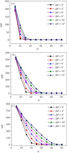
In Fig. 1, the MFs of the optimized Mo/Si multilayers with different N are shown. With the increase of N, all MF curves go down first and then converge to the values less than 1, fulfilling the design requirement MF ≤ 1. The results indicate that all desired broad angular phase retarders can be realized by using Mo/Si transmission multilayers with large enough N. For example, by optimizing the thickness of the layers, the Mo/Si transmission multilayers with more than 30 bilayers can all realize 90° phase retardation in the angular range from 43° to 47° (Δ θ = 4° ), however, with different transmissions.
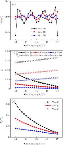
Figure 2(a) exhibits the phase retardation Δ ϕ of the optimized Mo/Si transmission multilayers with N = 30, 40, 50, and near 90° phase retardations have been achieved in the angular range from 43° to 47° (Δ θ = 4° ) by all three optimized multilayers. However, the s- and p-component transmissions Ts and Tp (Fig. 2(b)), and transmission ratio Ts/Tp (Fig. 2(c)) of these multilayers show totally different behaviors. The average Ts and Tp of the optimized multilayers in the desired angular range (from 43° to 47° ) decrease from 4.27% and 15.34% to 0.55% and 5.17% when N increases from 30 to 50. The lower transmission of the multilayer with more layers may be attributed to the absorption of its redundant layers. Furthermore, with the increase of N, the curve of transmission ratio Ts/Tp becomes flatter in the desired angular range, which means that Ts/Tp for different incident angle tends to be the same. The forming of such a flat Ts/Tp curve is beneficial for the perfect conversion of linearly to circularly polarized light in the broad angular region, because the throughputs of s- and p-polarized components can be equal in the broad angular region when the azimuth angle α of the broad angular phase retarder fulfills 
Besides, for a particular desired phase retardation Δ ϕ 0, if one wants to realize phase retarders with broader desired angular band Δ θ , Mo/Si multilayers with larger N are needed. For example, to design a 90° phase retarder (i.e., quarter-wave plate) working in the angular range from 44° to 46° (Δ θ = 2° ), Mo/Si transmission multilayers with at least 35 bilayers (N = 35) are needed according to our analysis. However, to realize a 90° phase retarder working in the angular range from 39° to 51° (Δ θ = 12° ), at least 50 bilayers (N = 50) are needed. In other words, the Mo/Si transmission multilayer with larger N could achieve broader angular phase retardation in the EUV region.
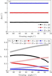
By comparing the optimization results shown in Figs. 1(a)– 1(c), we find that larger phase retardation Δ ϕ 0 needs more layers in the multilayer for a particular angular bandwidth Δ θ . The Mo/Si multilayer with larger N could be used to achieve larger phase retardation Δ ϕ 0 in a broad angular range for EUV. For instance, to obtain broad angular phase retarders with 30° , 60° and 90° phase retardation working in the angular range of 39° – 51° (Δ θ = 12° ), Mo/Si multilayers with 20, 35, and 50 are needed, respectively (Fig. 3(a)). The average Ts and Tp of the optimized multilayers in the desired range decrease from 19.95% and 32.57% to 1.42% and 4.9% when N increases from 20 to 50 (Δ ϕ 0 increases from 30° to 90° ) (Fig. 3(b)), just like the transmission performance of the multilayers shown in Fig. 2(b).
To study the structural characteristics of the designed broad angular phase retarders, the thickness distributions of the three optimized Mo/Si multilayers in Fig. 3 are shown in Fig. 4. Distinguished from the seed multilayers with periodic structures, all optimized multilayers show aperiodic structures with oscillating thickness distributions. The aperiodic structure characteristics of the optimized multilayers are predictable, because the periodic multilayers can only obtain a large phase retardation at the low- and high-angle sides of the Bragg peak, and cannot realize the broad angular phase retardation.[9] In addition, the oscillating bilayer thickness distributions exhibited in Fig. 4, which are beneficial for forming large phase retardations at different incident angles, are considered to be the reason for realizing the broad angular phase retardations. Furthermore, approximately the same oscillation amplitude of the bilayer thickness among the three optimized multilayer structures should be related to the same bandwidth Δ θ .
 | Fig. 4. The thickness distributions of the optimized Mo/Si multilayers in (a) 30° , (b) 60° , and (c) 90° phase retarders showed in Fig. 3. |
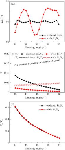
In practice, the fabrication of transmission Mo/Si multilayers without substrates or supporting membranes, i.e., free-standing transmission multilayers, still remain a great challenge, because the problems such as mechanical integrity will arise for the free-standing structures.[27] So, a low-absorption membrane, typically a 100 nm silicon nitride (Si3N4) membrane, is usually used to support the transmission Mo/Si multilayer. In Fig. 5, the influences of the 100 nm supporting Si3N4 membrane on the performances of a designed broad angular 90° phase retarder with N = 30 and Δ θ = 4° are shown.
Compared with the designed free-standing phase retarder, the one with a 100 nm supporting Si3N4 membrane presents nearly the same mean phase retardation (90.17° vs. 89.99° ) and a slightly larger standard deviation (0.46° vs. 0.05° ) in the desired angle region (43° to 47° ), as shown in Fig. 5(a). On the other hand, because of the absorption of the supporting membrane, the transmissions of both polarization components decrease when the supporting Si3N4 membrane is used (Fig. 5(b)). Fortunately, the transmission ratio is almost unchanged (Fig. 5(c)). The little change of phase retardation and transmission ratio caused by the supporting membrane indicates its small influence on the polarization characteristics of the designed phase retarder.[6]
In this paper, we described a method for designing broad angular phase retarders in the extreme ultraviolet region. A series of broad angular phase retarders with different phase retardations and different angular bandwidths were designed using Mo/Si multilayers with different layers. Particularly, by using a Mo/Si multilayer with 50 bilayers, a 90° broad angular phase retarder working at 90 eV in the angular range of 39° – 51° was obtained, providing 1.42% and 4.9% average transmissions for s- and p-polarized components, respectively. In addition, the polarization characteristics of the designed broad angular phase retarders were analyzed and compared. Compared with the traditional phase retarders designed with transmission periodic multilayers, the designed broad angular phase retarders possess lower sensitivity toward changing incident angle, and can be used for the polarization control of broad angular EUV sources.
| 1 |
|
| 2 |
|
| 3 |
|
| 4 |
|
| 5 |
|
| 6 |
|
| 7 |
|
| 8 |
|
| 9 |
|
| 10 |
|
| 11 |
|
| 12 |
|
| 13 |
|
| 14 |
|
| 15 |
|
| 16 |
|
| 17 |
|
| 18 |
|
| 19 |
|
| 20 |
|
| 21 |
|
| 22 |
|
| 23 |
|
| 24 |
|
| 25 |
|
| 26 |
|
| 27 |
|


