Thickness dependent manipulation of uniaxial magnetic anisotropy in Fe-thin films by oblique deposition
Gul Qeemat1, 2, He Wei1, 2, Li Yan1, 2, Sun Rui1, 2, Li Na1, 2, Yang Xu1, 2, Li Yang1, 2, Gong Zi-Zhao1, 2, Xie ZongKai1, 2, Zhang Xiang-Qun1, Cheng Zhao-Hua1, 2, †
State Key Laboratory of Magnetism and Beijing National Laboratory for Condensed Matter Physics, Institute of Physics, Chinese Academy of Sciences, Beijing 100190, China
School of Physical Sciences, University of Chinese Academy of Sciences, Beijing 100049, China


† Corresponding author. E-mail: zhcheng@iphy.ac.cn

Project supported by the National Basic Research Program of China (Grant Nos. 2015CB921403 and 2016YFA0300701), the National Natural Science Foundation of China (Grant Nos. 51427801, 11374350, and 51671212), and the Chinese Government Scholarship (Grant No. 2015GXYG37).

Abstract

The uniaxial magnetic anisotropy of obliquely deposited Fe(001)/Pd film on MgO(001) substrate is investigated as a function of deposition angle and film thickness. The values of incidence angle of Fe flux relative to surface normal of the substrate are 0°, 45°, 55°, and 70°, respectively. In-situ low energy electron diffraction is employed to investigate the surface structures of the samples. The Fe film thicknesses are determined to be 50 ML, 45 ML, 32 ML, and 24 ML (1 ML = 0.14 nm) by performing x-ray reflectivity on the grown samples, respectively. The normalized remanent magnetic saturation ratio and coercivity are obtained by the longitudinal surface magneto-optical Kerr effect. Here, the magnetic anisotropy constants are quantitatively determined by fitting the anisotropic magnetoresistance curves under different fields. These measurements show four-fold cubic anisotropy in a large Fe film thickness (50 ML) sample, but highly in-plane uniaxial magnetic anisotropies in thin films (24 ML and 32 ML) samples. In the obliquely deposited Fe films, the coercive fields and the uniaxial magnetic anisotropies (UMAs) increase as the deposition angle becomes more and more tilted. In addition, the UMA decreases with the increase of the Fe film thickness. Our work provides the possibility of manipulating uniaxial magnetic anisotropy, and paves the way to inducing UMA by oblique deposition with smaller film thickness.

1. Introduction

Magnetic anisotropy may be of technical importance for the application of magnetoresistive (MR) devices. It has been recognized that higher perpendicular magnetic anisotropy is desirable for future high-density magnetic recording (HDR) and high frequency magnetic devices. For various devices in the magnetoresistive random access memory (M-RAM) and the hard disk drive (HDD) head component, an in-plane magnetized film with a uniaxial anisotropy is being used.[1]

The oblique deposition of magnetic films can effectively induce a highly in-plane uniaxial magnetic anisotropy.[2,3] In an obliquely-deposited ferromagnetic film, the coercive field increases sharply as the deposition angle becomes more and more tilted. In addition, there is a steep transition between magnetization directions when measured along the easy axis of the structures, leading to a very square hysteresis loop. The evaporation of Co and Co alloys onto the polymer substrate has been used to produce medium for high-density magnetic recording tape.[4] In oblique deposition, magnetic anisotropy is usually associated with shadow and steering effect, resulting in elongated grain structures or ripples on a nanometer scale. These elongated grain structures and ripples give rise to in-plane uniaxial magnetic anisotropy.[58] The anisotropic surface roughness of obliquely deposited Ta, Pt, or Co underlayers also causes highly uniaxial magnetic anisotropy.[912] While in the magnetic films deposited at normal incidence, the magnetostatic coupling arising from the anisotropic undulation of the interface between the underlayer and the magnetic film causes in-plane magnetic anisotropy.[13] Previous reports have shown that in Pd/obliquely deposited Fe/Al2O3(0001), despite the existence of protective Pd overlayer and insulating Al2O3(0001) substrate, the obliquely deposited Fe film still shows an explicit uniaxial magnetic anisotropy energy.[14] In recent years, the interfacial magnetic anisotropy and coercive field have been studied in many systems including 3d magnetic metal covered by non-magnetic films.[1518]

Up to now, different characterization tools have been used to measure magnetic anisotropy constants, such as ferromagnetic resonance (FMR),[19] hysteresis loop measurement, torque measurement,[20] rotating magneto-optical Kerr effect (ROT-MOKE),[21] and transverse biased initial inverse susceptibility and torque (TBIIST).[22] For ultra-thin films, coherent domain rotation magnetization reversal does not always occur, particularly when the applied field is lower than the saturation field. Therefore, it is a challenge to accurately determine the magnetic anisotropy constant from the magnetization hysteresis loop. Anisotropic magnetoresistane (AMR) was therefore considered as an accurate technique for magnetic anisotropy measurement in thin films.[2328] In order to ensure a real single domain rotation, an appropriately large field is required.

The Fe/Pd is an excellent candidate for studying the relationship between atomic structure and magnetism in low dimensional heterostructures. In the past, most of the work has been carried out on the growth behavior and structure of Fe thin films deposited on MgO(001) substrates.[2936] However, the magnetic properties of Fe films on MgO(001) substrates still need to be studied in more detail. In this paper, we report the magnetic behavior of Fe film obliquely deposited on MgO(001) substrate as a function of deposition angle and film thickness. The magnetic properties are measured by azimuthal rotation through ex-situ magneto-optical Kerr effect (MOKE) at room temperature. In addition, the magnetic anisotropy constants are quantitatively determined by using the standard four-point method of anisotropic magnetoresistance (AMR) measuring setup.

2. Experimental details
2.1. Sample preparation

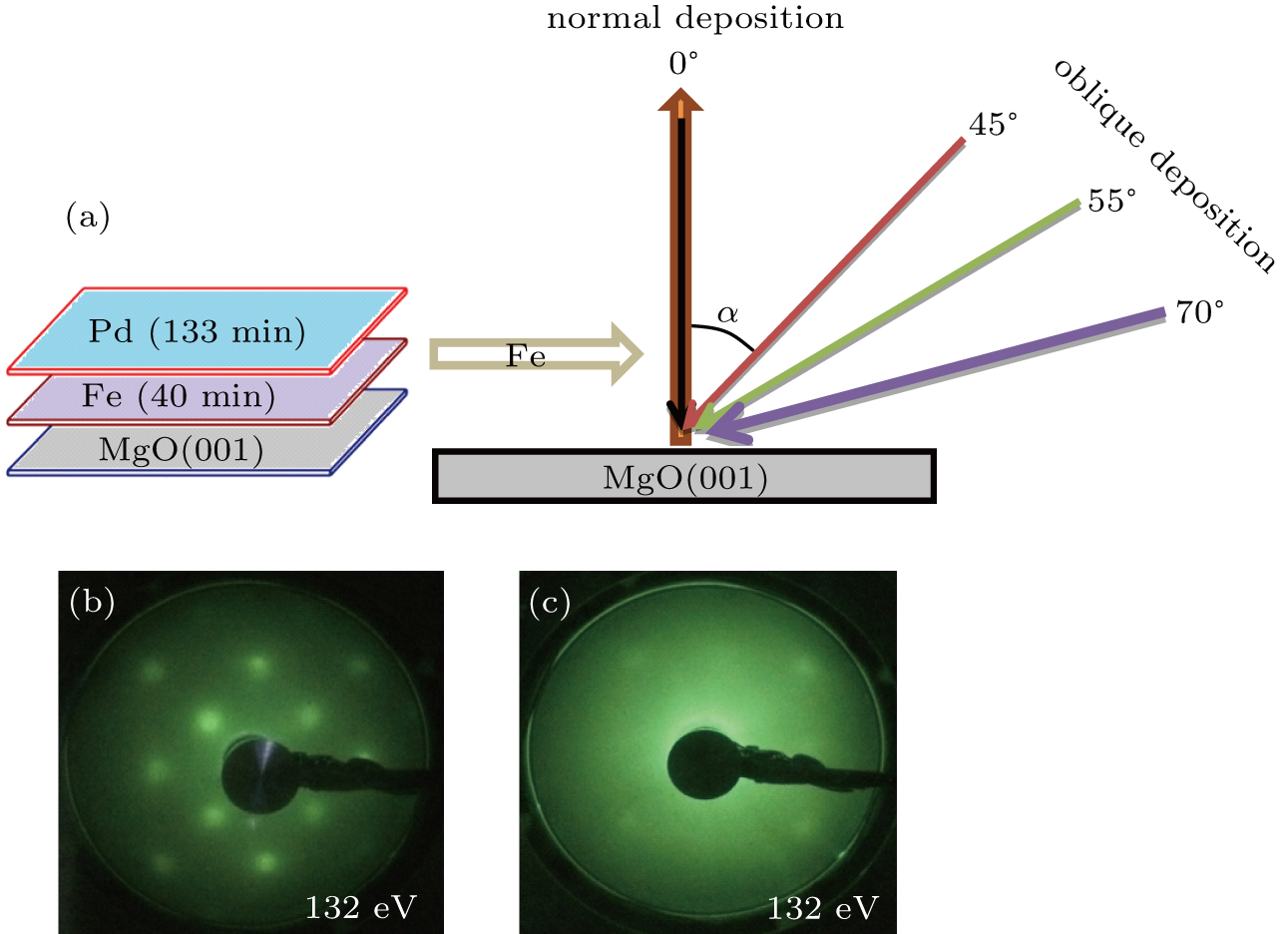
The Fe films were deposited on cleaned MgO(001) substrates by molecular beam epitaxy (MBE) in an ultra-high vacuum (UHV) system with a base pressure of 2.0 × 10⁻¹⁰ mbar. The MgO(001) substrate had been first heated at 700 °C for 2 h to remove the adsorbed gas from the surface before the film was deposited. The clean surface of MgO(001) was confirmed by in situ low energy electron diffraction (LEED) equipped within the Omicron UHV system. Subsequently, the Fe (99.995% purity) film was deposited on the MgO(001) substrate by the oblique-incidence deposition method. The Fe films with thicknesses of 50 ML, 45 ML, 32 ML, and 24 ML were obtained by varying the oblique deposition angle (α) relative to the normal surface of the substrate. The Fe film deposition angles (α) were 0°, 45°, 55°, and 70°, respectively. The growth time of Fe film for all samples was kept the same (i.e., 40 min) in the deposition processes. Therefore, the deposition rate of Fe film was 0.6–1.25 ML/min, while the substrate was still kept at room temperature. Before taken out of the UHV chamber, all samples were covered with a layer of ∼ 6 nm Pd, normally deposited under pressure of 5.0 × 10⁻⁹ mbar. Figure 1(a) shows a schematic configuration of the samples synthesis.

Fig. 1. (color online) (a) Schematic configuration of sample growth, (b) LEED pattern of MgO(001) substrate, and (c) Fe thin film deposited on MgO(001) with α = 0° (normal deposition).
2.2. Diagnostic techniques

in situ low energy electron diffraction (LEED) equipped within the Omicron UHV system was employed to investigate the surface structure of the samples. The x-ray reflectivity (XRR) was performed to determine the film thickness and roughness for all samples by a Bruker D-8 x-ray diffractometer using Cu radiation (λ = 0.15405 nm). The ex-situ longitudinal MOKE measurements were carried out at room temperature and described elsewhere.[37,38] In addition, the magnetic anisotropy constants were determined quantitatively by fitting the angle-dependent anisotropic magnetoresistance (AMR) curves. The home-made AMR setup consists of a Wheatstone bridge, a lock-in amplifier (Stanford Research Systems SR830 DSP), and a rotational magnetic stage around a stationary sample. In the experiments, a sufficiently large and stable field was used to guarantee a true single-domain behavior of the specimen. The sample size was 10 mm × 3 mm × 0.5 mm for AMR measurements, which were performed with a standard four-point method.

3. Results and discussion
3.1. LEED analysis

Figure 1(b) shows the in situ LEED (2 × 2) pattern of MgO(001). The surface structure of the Fe film normally deposited is also investigated by in situ LEED, and the cubic Fe(001) layer is epitaxially grown on the MgO(001) surface as shown in Fig. 1(c). Previous study of MgO showed that it retained its bulk body centered cubic (BCC) structure due to the lattice mismatch of 4%, and there might be a tetragonal distortion in the Fe.[39,40] As shown in Fig. 1(c), due to the epitaxial relationship, the Fe lattice is rotated by 45° relative to the MgO lattice, i.e., the well-known relation Fe〈1 1 0〉 ∥ MgO〈1 0 0〉. During the oblique deposition, a self-shadowing effect takes place, resulting in the formation of grains in the plane of the film that is elongated perpendicularly to the incident flux direction and with an aspect ratio increasing at a larger deposition angle. Therefore, all the other LEED patterns are almost similar and it is difficult to distinguish the LEED pattern of the Fe film with large oblique deposition angle. The energy provided during the LEED pattern observation is 132 eV.

3.2. XRR analysis

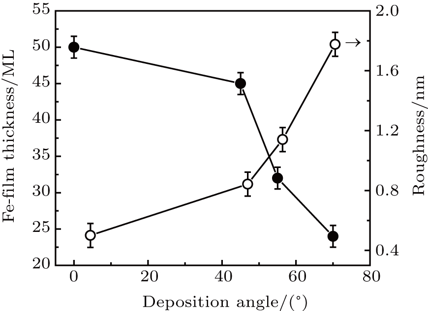
The XRR usually can be performed on the grown sample to determine the film thickness, roughness, and density. Figure 2 shows the XRR experimental curve and its fitting for determining the film thickness and roughness of the sample with α = 0° (50 ML). The XRR experimental curves and their fittings for the other samples are not shown here. The fitting parameters are accurately determined by simulating (red line) the experimental curve (open circles) and are presented in Table 1. Figure 3 clearly shows that the Fe film thickness (tFe) decreases and the roughness (σ) increases with the increase of oblique deposition angle (α).
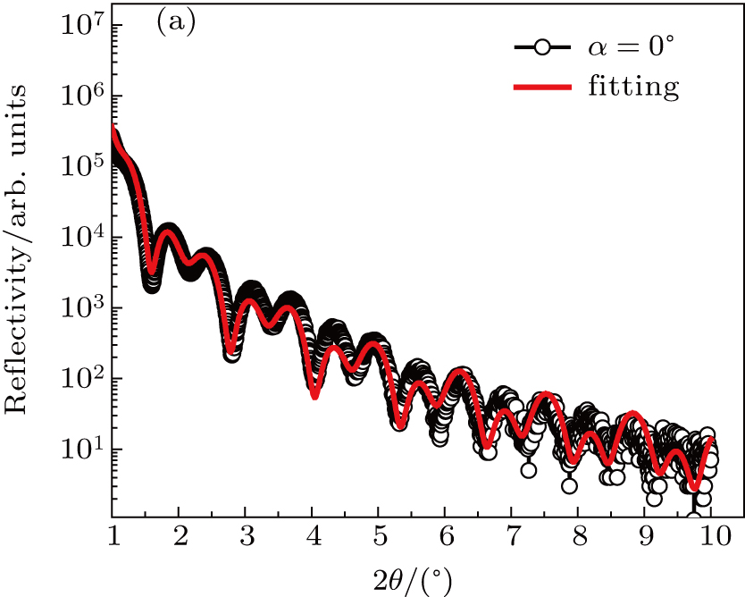
Fig. 2. (color online) X-ray reflectivity spectra recorded on 0°-Fe(001)/Pd thin film, with fitting parameters accurately determined by simulating (red line) the experimental curve (open circles).
Fig. 3. X-ray reflectivity measurement of Fe-film thickness (tFe) and roughness (σ) as a function of deposition angle α.
Table 1.

X-ray reflectivity measurements of film thickness and roughness.

.
3.3. MOKE analysis

The magnetic properties are measured by azimuthal rotation through the ex-situ MOKE at room temperature. Figure 4 shows typical MOKE hysteresis loops taken at different values of angle φH for all four samples. More detailed studies reveal the magnetic behaviors of these films, the conventional square hysteresis loops, and loops with multi-jumps, which are dependent on the direction of the magnetic field. The anisotropic geometry of each sample is the same as that in previous work on Fe/MgO(001).[41] The UMA along Fe[100] is very important to create a multi-jump magnetic switching process. The experimental results of Zhan et al. showed that a considerable UMA along [100] may lead to three-jump loops in some directions of the external magnetic field.[42] These multi-jump loops are also observed in our samples, and we have two considerable UMAs along [100]. Figures 4(c) and 4(d) show one jump at φH = 45°, two-jumps at φH = 126°, and three-jumps at φH = 153° given by typical MOKE; φH is the angle of the applied field relative to the [110] hard axis. The UMA along Fe[100] originates from oblique-incidence growth geometry. It is perpendicular to the incident flux direction and results from the self-shadowing effect. These unusual magnetic switching processes are caused by superimposed uniaxial magnetic anisotropy, which can be explained by the magnetization reversal mechanism of the 90° domain wall.[43] Thus, the origin of uniaxial magnetic anisotropic component is the incident angle of the Fe atomic flux relative to the normal plane of the substrate. Since this effect was first observed in the Fe/Pd superlattice with a very thin Fe layer (< 20 Å), it was assumed that the magnetic anisotropy may occur, because the roughness of the Fe/Pd interface (about 5 Å) may have an anisotropic morphology, which is caused by the incident angle of the Fe atomic flux. A similar uniaxial magnetic anisotropy was also found in a single 800 Å-thick Fe film grown directly on MgO with a 15 Å Pd cap layer.[44]
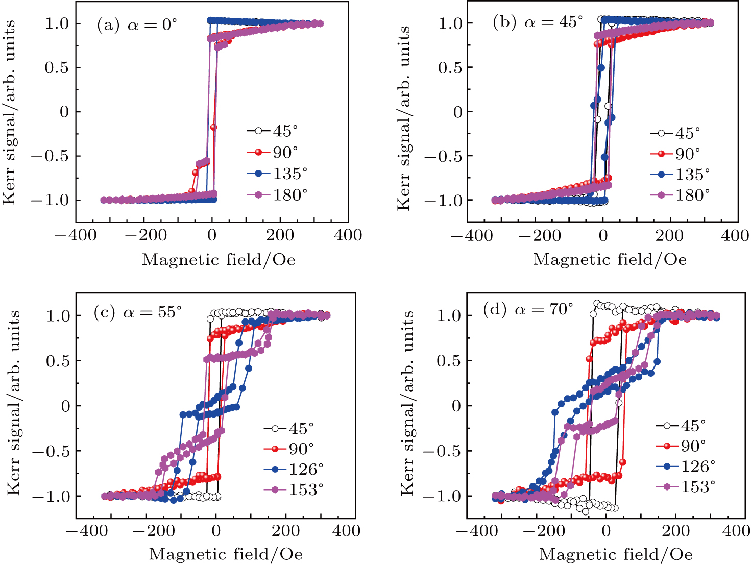
Fig. 4. (color online) Typical magnetic hysteresis loops of Fe films at different deposition angles: (a) 0°, (b) 45°, (c) 55°, and (d) 70°.

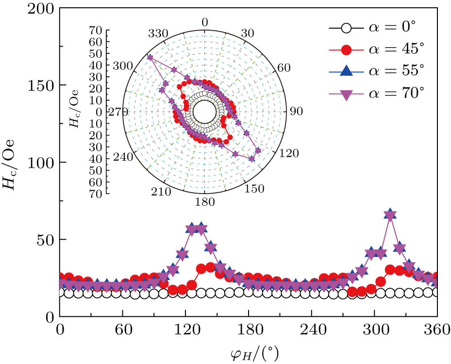
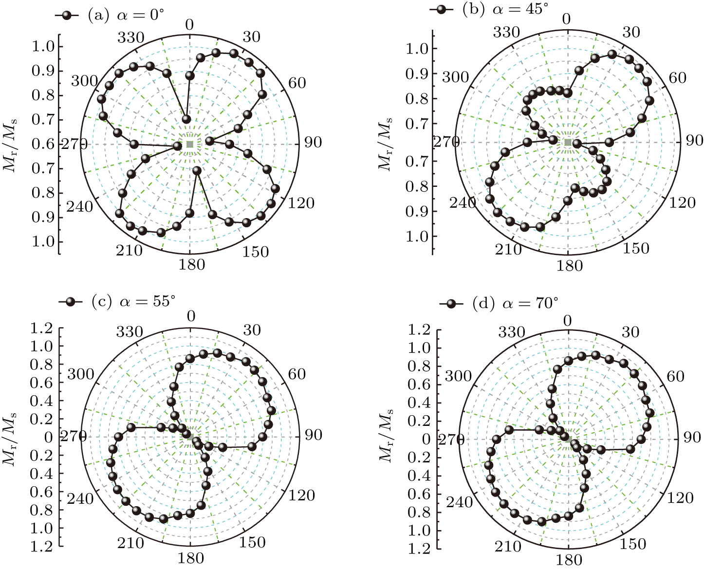
Therefore, on the contrary, our results show that the origin of the magnetic anisotropy is not the interface effect, nor the bulk property of the Fe layer, but it may be caused by the thickness of the Fe film changing with the oblique angle in the deposition process. The experimental dependency on the field direction of the coercive field (Hc) is plotted in Fig. 5. In order to facilitate the investigation of the anisotropic symmetry, the same data are plotted in polar coordinates in the inset. The Hc of the sample with α = 0° (50 ML) measured at φH = 0° is 16 Oe and shows an invariant behavior with the azimuthal angle (φH). When the oblique deposition angle increases to α = 45° (45 ML), the Hc measured at φH = 0° is increased to 25 Oe and shows a non-constant behavior with the azimuth (φH). Particularly in the case of the samples with α = 55° and 70°, the Hc values increase to 55 Oe and 66 Oe respectively, at the values of easy axe φH = 126° and 315° just as the other samples do. This implies the uniqueness of the 32 ML and 24 ML samples with α = 55° and 70°. Because of the tilting shape of the hysteresis loop, Hc drops to 21 Oe at the hard axes (φH = 180° and 360°), which clearly indicates the presence of uniaxial magnetic anisotropy. Quantitatively, Table 2 shows the difference , i.e., subtracting the coercivity along the easy axis () from the coercivity along the hard axis (). The values of Hc are deduced from the widths of the split half-loops. If the film had a coercive field less than the uniaxial anisotropy field, this effect would be simply regarded as a (relatively large) difference between the coercive forces in the two directions. Obviously, the larger the difference, the more alignment becomes a sign of the absence of disorder, that is, it shows single crystallinity of the sample. Also, it can be clearly seen from Table 2 that the increase of oblique deposition angle leads to more alignment and highly uniaxial magnetic anisotropy. From the longitudinal MOKE data for all samples, the angle dependent normalized remanent magnetic saturation ratio (Mr/Ms) polar plots are shown in Fig. 6. Previous work reported that the Fe thin films on MgO(001) substrates have four-fold symmetry with strong magnetic anisotropy.[45] Figure 6(a) clearly shows that the angle dependent normalized remanence of the normally deposited (α = 0°) sample exhibits four-fold symmetry. When the Fe film thickness is large (50 ML), the four-fold cubic anisotropy is dominant to the UMA caused by oblique deposition.[46] In the case of α = 45° (45 ML) sample, a weak four-fold symmetry is observed, as shown in Fig. 6(b). However, the samples deposited with α = 55° and 70° exhibit highly in-plane uniaxial magnetic anisotropy as shown in Figs. 6(c) and 6(d), respectively. This implies that the self-shadowing effect occurs during the oblique deposition, resulting in the formation of grains in the film plane perpendicular to the direction of the incident flux, and with aspect ratio increasing at a higher deposition angle. Therefore, the inhomogeneous distribution of the adatoms (roughness) occurs. That is why an in-plane uniaxial magnetic anisotropy is induced by the roughness caused by oblique deposition. Therefore, as the oblique deposition angle increases, the roughness also increases, resulting in the increase of UMA.[47] These measurements also show four-fold cubic anisotropy in large Fe film thickness (50 ML) sample, but exhibit highly in-plane uniaxial magnetic anisotropy in thin films (24 ML and 32 ML) samples.

Fig. 5. (color online) Experimental dependency on the field direction of coercive field (Hc), with the same data plotted in polar coordinates in the inset.
Fig. 6. Angular dependent normalized residual polar plots of longitudinal MOKE data for all four samples.
Table 2.

Magnetic anisotropy constants (Kl and Ku) and coercivity field (Hc) measured by using torque curves and MOKE, respectively.

.
3.4. AMR analysis

In order to quantitatively determine the constants of magnetocrystalline anisotropy Kl and uniaxial magnetic anisotropy Ku for all four samples, the torque curves are obtained.

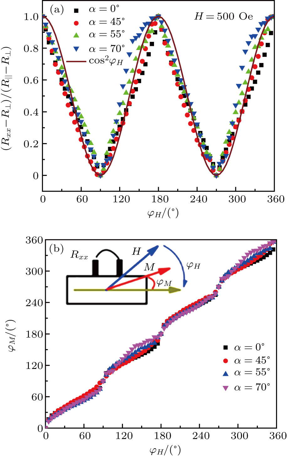
The resistance in ferromagnetic metallic film is a function of angle φM, which is the angle between the magnetization and current (inset of Fig. 7(b)), and can be written as[48,49]

The maximum (R) and minimum (R) correspond to the magnetoresistance when the external magnetic field (H) is parallel and perpendicular to the current direction.

Fig. 7. (color online) (a) Angle-dependent MR measurement (H = 500 Oe) at different deposition angle α and with cos2(φH) as a reference for comparison. (b) Correlation between φH and φM at different deposition angle α. Inset shows schematic configuration of sample resistance measurement as a function of angle φM, which is between the magnetization (M) and current (I).

For real single domain rotation and excluding ordinary magnetoresistance effect, it is necessary to impose a higher external magnetic field than the saturation field.

The AMR curves of all four samples are plotted in Fig. 7(a). By changing the direction of the external magnetic field H, the magnetization M follows the orientation of the external applied field, so that the value of AMR exhibits an oscillatory behavior. However, due to magnetic anisotropy, MFe is no longer consistent with the external field (H) in the rotation process, that is, φMφH. Therefore, the AMR curve does not follow this cos2φH relationship. The correlation between φH and φM can be obtained from Fig. 7(a) and drawn in Fig. 7(b). Obviously, it can be expressed as

In fact, in the presence of an external magnetic field, two types of torques act on the magnetization. The torque of magnetization due to the easy axis can be expressed as
The first term is two-fold UMA and the second term is four-fold MCA. The torque of the external magnetic field can be expressed as
where μ0 is the permeability of free space (μ0 = 4π × 10−7 H/m) and Ms represents the saturation magnetization (for bulk Fe, Ms = 1.74 × 10⁶ A/m).

In order to compare the above two types of torques, the normalized torque is introduced below

The expression of total energy including magnetic anisotropy energy and Zeeman energy can be expressed as
where the first and the second terms represent two-fold UMA and four-fold MCA, respectively, and the last term is the Zeeman energy. In the case of equilibrium (∂E/∂φM = 0), the normalized magnetic torque is given by

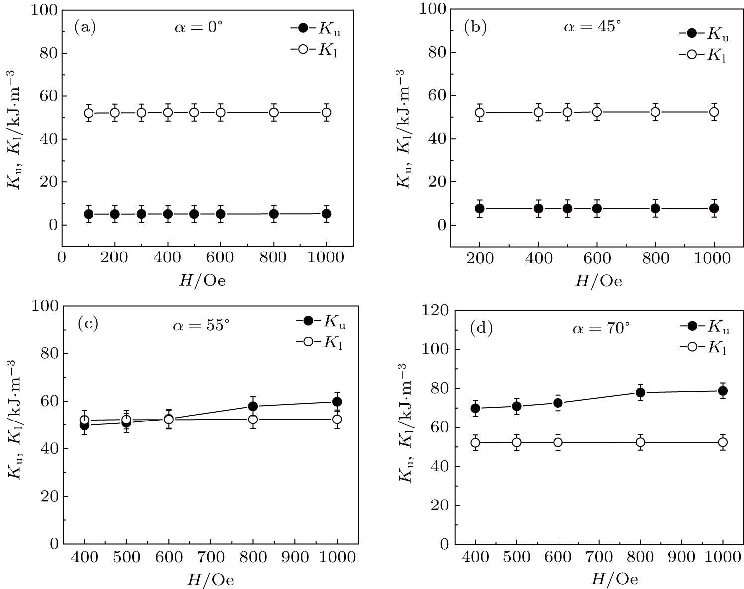
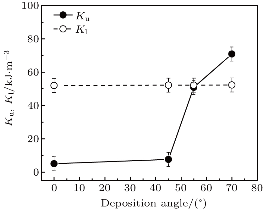
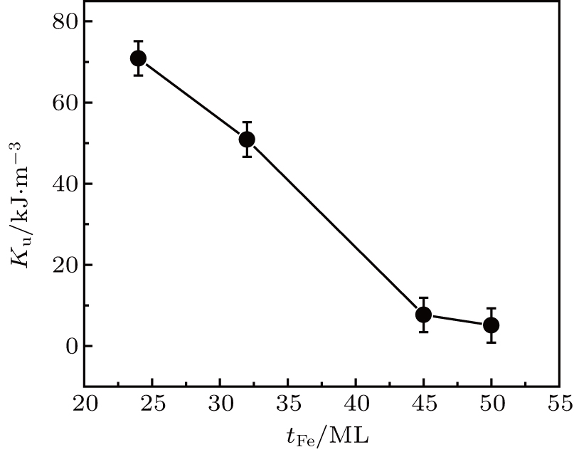
The normalized magnetic torque curves for all four samples are shown in Fig. 8. The values of magnetic anisotropy constants Kl and Ku are determined by fitting the normalized torque curves with Eq. (7). It is obvious that the sample deposited with α = 0° (normal deposition) shows the minimum value of UMA, Ku = 5.0 × 10³ J/m3, with dominant four-fold MCA Kl = 5.2 × 10⁴ J/m3, and with higher deposition angle α = 70°, UMA obviously reaches the maximum value Ku = 7.1 × 10⁴ J/m3. The values of magnetic anisotropy constants Ku and Kl under variant external magnetic fields are plotted in Fig. 9. Both Ku and Kl show the almost invariable behaviors of the magnetic fields applied externally, which are in good agreement with those of the Fe/Si(001) films.[50] The determined values of Ku and Kl for all samples are also plotted against the deposition angle (α) as shown in Fig. 10. Table 2 shows the values of Ku and Kl obtained from the AMR measurements. It can be clearly observed that Ku increases with the increase of oblique deposition angle, while Kl shows an invariant behavior. In addition, Ku decreases with increasing Fe film thickness (tFe) as shown in Fig. 11. Our measurements show four-fold cubic anisotropy in a large Fe film thickness (50 ML) sample and the recognition of superimposed highly in-plane uniaxial magnetic anisotropy in thin film (24 ML and 32 ML) samples. Thus, it is concluded that UMA may also be induced by oblique deposition with smaller film thickness.
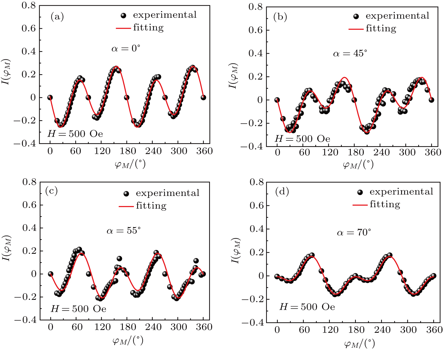
Fig. 8. (color online) Normalized magnetic torque curves of Fe films deposited on Mg(001) substrate at different deposition angles: (a) 0°, (b) 45°, (c) 55°, and (d) 70°.
Fig. 9. Anisotropy constants Ku and Kl versus applied magnetic field (H) of Fe thin films deposited at different deposition angles: (a) 0°, (b) 45°, (c) 55°, and (d) 70°.
Fig. 10. Plots of Ku and Kl versus deposition angle α.
Fig. 11. UMA Ku versus Fe-film thickness tFe.
4. Conclusions

In this work, our measurements show four-fold cubic anisotropy in thick Fe film (> 32 ML) and superimposed highly in-plane uniaxial magnetic anisotropy in thin film. The in-plane UMA Ku induced by oblique deposition shows an increasing behavior with the deposition angle while Kl shows an invariant behavior. The values of MCA constant Kl and UMA constant Ku each exhibit almost a linear behavior with the applied field. In addition, the UMA Ku decreases with Fe film thickness increasing. The higher oblique deposition angle also results in higher coercivity.

Reference
[1] Chowdhury N Bedanta S 2014 AIP Adv. 4 027104
[2] Knorr T G Hoffman R W 1959 Phys. Rev. 113 1039
[3] Smith D O 1959 J. Appl. Phys. 30 S5264
[4] Chiba K Sato K Ebine Y Sasaki T 1989 IEEE Trans. Consum. Electron. 35 421
[5] West F G 1964 J. Appl. Phys. 35 1827
[6] Hashimoto T Hara K Okamoto K Hashimoto T Fujiwara H 1973 J. Phys. Soc. Jpn. 34 1415
[7] Hoshi Y Suzuki E Naoe M 1996 J. Appl. Phys. 79 4945
[8] Alameda J M Carmona F Salas F H Alvarez-Prado L M Morales R Perez G T 1996 J. Magn. Magn. Mater. 154 249
[9] McMichael R D Lee C G Bonevich J E Chen P J Miller W Egelhoff W F 2000 J. Appl. Phys. 88 5296
[10] Hadley M J Pollard R J 2002 J. Appl. Phys. 92 7389
[11] Zhao Z Mani P Mankey G J Gubbiotti G Tacchi S Spizzo F Lee W T Yu C T Pechan M J 2005 Phys. Rev. 71 104417
[12] Umlor M T 2005 Appl. Phys. Lett. 87 082505
[13] Fukuma Y Lu Z Fujiwara H Mankey G J Butler W H Matsunuma S 2009 J. Appl. Phys. 106 076101
[14] Chi C S Wang B Y Pong W F Ho T Y Tsai C J Lo F Y Chern M Y Lin W C 2012 J. Appl. Phys. 111 123918
[15] Hillebrands B Boufelfel A Falco C M Baumgart P Gu\textasciidieresis ntherodt G Zirngiebl E Thompson J D 1988 J. Appl. Phys. 63 3880
[16] Engel B N Wiedmann M H Van Leeuwen P A Falco C M 1993 Phys. Rev. 48 9894
[17] Beauvillain P Bounouh A Chappert C Megy R Ould-Manfoud S Renardt J P Viellet P Weller D Corno J 1994 J. Appl. Phys. 76 6078
[18] Schumann F O Buckley M E Bl J A C 1994 J. Appl. Phys. 76 6078
[19] Rezende S M Moura J A S De Aguiar F M Schreiner W H 1994 Phys. Rev. B 49 15105
[20] Yaegashi S Kurihara T Satoh K 1997 J. Appl. Phys. 81 6303
[21] Mattheis R Quednau G 1999 J. Magn. Magn. Mater. 205 143
[22] Garreau G Hajjar S Bubendorff J L Pirri C Berling D Mehdaoui A Stephan R Wetzel P Zabrocki S Gewinner G Boukari S Beaure paire E 2005 Phys. Rev. 71 094430
[23] McGuire T R Potter R I 1975 IEEE Trans. Mag. 11 1018
[24] Dahlberg E D Riggs K Prinz G A 1988 J. Appl. Phys. 63 4270
[25] Miller B H Dahlberg E D 1996 Appl. Phys. Lett. 69 3932
[26] Krivorotov I N Leighton C Nogues J Schuller I K Dahlberg E D 2002 Phys. Rev. 65 100402
[27] Cao W N Li J Chen G Zhu J Hu C R Wu Y Z 2011 Appl. Phys. Lett. 98 262506
[28] Li J Jin E Son H Tan A Cao W N Hwang C Qiu Z Q 2012 Rev. Sci. Instrum. 83 033906
[29] Martínez Boubeta C Clavero C García-Martín J M Armelles G Cebollada A Balcells Ll Menéndez J L Peiró F Cornet A Toney Michael F 2005 Phys. Rev. 71 014407
[30] Qing-feng Zhan Stijn Vandezande Chris Van Haesendonck 2007 Appl. Phys. Lett. 91 122510
[31] Zhan Q F Vandezande S Kristiaan T Haesendonck C V 2009 Phys. Rev. 80 094416
[32] Spurgeon Steven R Sloppy Jennifer D Runzhe Tao Klie Robert F Lofl Samuel E Baldwin Jon K Amit Misra Taheri Mitra L 2012 J. Appl. Phys. 112 013905
[33] Lee S C Kim K S Lee S H Pi U H Kim K Jang Y Chung U I 2013 J. Appl. Phys. 113 023914
[34] Mallik S Chowdhury N Bedanta S 2014 AIP Adv. 4 097118
[35] Ma T P Zhang S F Yang Y Chen Z H Zhao H B Wu Y Z 2015 J. Appl. Phys. 117 013903
[36] Kozioł-Rachwał A Slezak T Nozaki T Yuasa S Korecki J 2016 Appl. Phys. Lett. 108 041606
[37] Du H F He W Liu H L Fang Y P Wu Q Zou T Zhang X Q Sun Y Cheng Z H 2010 Appl. Phys. Lett. 96 142511
[38] Liu H L He W Du H F Fang Y P Wu Q Zhang X Q Yang H T Cheng Z H 2012 Chin. Phys. 21 077503
[39] Urano T Kanaji T 1988 J. Phys. Soc. Jpn. 57 3043
[40] Liu C Park Y Bader S D 1992 J. Magn. Magn. Mater. 111 L225
[41] Hu B He W Ye J Tang J Zhang Y S Syed S A Zhang X Q Cheng Z H 2015 Chin. Phys. 24 077502
[42] Zhan Q F Vandezande S Haesendonck C V Temst K 2007 Appl. Phys. Lett. 91 122510
[43] Zhan Q F Vandezande S Temst K Haesendonck C V 2009 Phys. Rev. 80 094416
[44] Childress J R Kergoat R Durand O George J M Galtier P Miltat J Schuhl A 1994 J. Magn. Magn. Mater. 130 13
[45] Hu B He W Ye J Tang J Zhang Y S Ahmad S S Zhang X Q Cheng Z H 2015 Sci. Rep. 5 14114
[46] Postava K Jaffres H Schuhl A Nguyen Van Dau F Goiran M Fert A R 1997 J. Magn. Magn. Mater. 172 199
[47] Fang Y P He W Liu H L Zhan Q F Du H F Wu Q Yang H T Zhang X Q Cheng Z H 2010 Appl. Phys. Lett. 97 22507
[48] Tang H X Kawakami R K Awschalom D D Roukes M L 2003 Phys. Rev. Lett. 90 107201
[49] Wu D Wei P Johnston-Halperin E Awschalom D D Shi J 2008 Phys. Rev. 77 125320
[50] Ye J He W Wu Q Hu B Tang J Zhang X Q Chen Z Y Cheng Z H 2014 Appl. Phys. Lett. 105 102406