


Modeling the reactive sputter deposition of Ti-doped VO x thin films*
[Wang Taoa) , Yu Hea)†  , Gu De-En
a) , Guo Ruia) , Dong Xianga) , Jiang Ya-Donga) , Wu Rui-Linb) ]
, Gu De-En|
|


†Corresponding author. E-mail: yuhe@uestc.edu.cn
*Project partially supported by the National Natural Science Foundation of China (Grant Nos. 61405027, 61421002, and 61235006) and the Postdoctoral Science Foundation of China (Grant No. 2014M562296).
In this paper an original numerical model, based on the standard Berg model, is used to simulate the growth mechanism of Ti-doped VO x deposited with changing oxygen flow during reactive sputtering deposition. Ti-doped VO x thin films are deposited using a V target with Ti inserts. The effects of titanium inserts on the discharge voltage, deposition rate, and the ratio of V/Ti are investigated. By doping titanium in the vanadium target, the average sputtering yield decreases. In this case, the sputter erosion reduces, which is accompanied by a reduction in the deposition rate. The ratio between V content and Ti content in the film is measured using energy-dispersive x-ray spectroscopy (EDX). A decrease in the vanadium concentration with the increasing of the oxygen flow rate is detected using EDX. Results show a reasonable agreement between numerical and experimental data.
Vanadium oxide has been studied widely due to its remarkable properties.[1, 2] VOx films with mixed phases can be tailored to meet the demands for reasonable resistivity and relatively high temperature coefficient of resistivity (TCR), and these materials have become the mainstream technology in the fast booming uncooled infrared image market. Therefore, research on the preparation techniques of VOx thin films has been greatly stimulated.
Vanadium oxide thin films have been widely prepared by a reactive magnetron sputtering method.[3] However, this process is very nonlinear and usually exhibits a hysteresis behavior with respect to the reactive gas flow. In order to understand this phenomenon, Berg and Nyberg[4] and Jonsson et al.[5] proposed a qualitative model to describe the reactive sputtering deposition in a steady state, and recently the extensions to this model have been published[6– 10] including the deposition by reactive co-sputtering from several elemental targets.[10] The physical and chemical parameters of vanadium oxides can be modified by doping with other elements. Especially, doping the VO2 thin films with the transition metals is known to largely affect the properties of the metal– insulator transition (MIT).[11, 12] Placing inserts in the racetrack is a common technique to change the thin film composition during reactive magnetron sputtering. This method is adopted in this paper using a vanadium target and titanium pieces. Despite the fact that doped VO2 is widely deposited, few papers describe a numerical model to study the reactive sputtering deposition of this structure. Therefore, the effects of the doped Ti on the concentration of film compositions, sputter/deposition rate and the target voltage behavior are investigated by both numerical modeling and experimental data in this paper. Results between the numerical approach and experimental data are compared in order to evaluate the proposed model.
The mathematical model describing the sputtering system is shown in Fig. 1. The total input rate of the reactive gas (oxygen) is denoted as Qtot. In this paper, it is assumed that the film structure is a mixture of V, VO2, Ti, and TiO2, then the target surface can be divided into four parts (see Fig. 1). The fractions of V, VO2, Ti, and TiO2 at the target will be called θ t1, θ t2, θ t3, and θ t4, respectively. θ s1, θ s2, θ s3, and θ s4 are fractions of collecting area covered by V, VO2, Ti, and TiO2, respectively.
It is assumed that the gettering of reactive gas onto metal vanadium and metal titanium contributes to the formation of VO2 and TiO2 on the target respectively, which will increase θ t2 or θ t4, respectively. For the metal vanadium atoms sputtered from the target, if the atom comes from the fraction of θ t1 and deposits on the substrate surface which previously consisted of VO2, then the fraction of θ s1 will increase and the fraction of (1 − θ s1) will decrease. Furthermore, when the compound of VO2 sputtered from the target deposits on the substrate which previously consisted of V, Ti or TiO2, then the corresponding fraction of (1 − θ s2) will decrease and the fraction of VO2 will increase. However, the fraction of flux (J/q)Ytiθ tiAt deposited onto the fraction θ si of the collecting area As will not change the value of θ si.
 | Fig. 1. Schematic diagram of the conditions at the target and collecting area during reactive sputtering with two reactive gases. The symbols are defined in the text. |
By making the above assumptions, and combining with the simplifications presented earlier, [4] the balance equations for the conditions on the target should be rewritten as follows:

Here J is the ion-current density, q is the elementary electronic charge, α 1 is the probability (sticking coefficient) for an oxygen molecule to react with a vanadium atom that comes from the θ t1 fraction of the target, l1 is the stoichiometry of VO2, At is the target area, and F represents oxygen molecules/ unit area and time.
Equation (1) determines the balance of the vanadium atom fraction (θ t1) on the target. For simplicity, the material sputtered from the surface fraction (J/q)Yt2θ t2At is assumed to be in the state of molecules, irrespective of whether the material is ejected in atomic or molecular form. The only way of sputtering the compound molecules is to react between neutral reactive gas molecules and the elemental non-reacted vanadium atoms, i.e.,

Moreover, equation (2) determines the balance of the fraction of θ t3 on the target. Here, l2 is the stoichiometry of the TiO2. The reaction between titanium atoms and the reactive gas atoms will contribute to a decrease in the value of θ t3. On the other hand, the TiOx compounds are sputtered from the surface fraction θ t4, which will increase the fraction of θ t3. It is also noted that all the compound fractions are summed into unity (Eq. (3)). An expression for A can be formulated in Eq. (4), which states that A is identical to the ratio between the total number of sputtered vanadium atoms and that of sputtered titanium atoms on the target. Under steady state conditions, the fraction A in the target is constant.


At a steady state, the contribution to an increase in θ si must be identical to the contribution to a decrease in θ si. This leads to the following balance equations (Eqs. (5) through Eq. (8)) for the collecting area As.
Equation (5) determines the balance of the fraction θ s2 on the substrate. The fraction of flux (J/q)Yt2θ t2At that deposits onto the fraction (1 − θ s2) will increase the value of θ s2. Obviously, the reactions between O2 and vanadium atoms at the substrate surface will increase θ s2. The fraction of flux (J/q)(Yt1θ t1 + Yt3θ t3 + Yt4θ t4) that deposits onto the fraction (θ s2) will contribute to a decrease in θ s2. Therefore

Like the above, the steady-state equation for the fractions of Ti and TiOx on the substrate may therefore be given as


Finally, the sum of fractions (θ s1, θ s2, θ s3, θ s4) is equal to 1, as in the case of the target surface:

Therefore, compound formation by reaction between oxygen molecules and vanadium, titanium at the target will consume reactive gas molecules Qt1, Qt2 reactively. The consumption (number of oxygen molecules per unit time) at the target Qti can be obtained from Eq. (9)[13] as follows:

While the consumption Qsi at the collecting area As can be expressed below


The remaining part Qp of the reactive gas will escape from the processing chamber through the pumping system, and it is expressed as[14]

The total supply rate of the reactive gas is denoted as Qtot given by

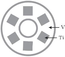
Ti-doped VOx thin films were deposited using V target with Ti inserts. The geometrical model of the target is shown in Fig. 2. A water-cooled planar vanadium metal target with a purity level of 99.99% was used in these experiments. The vanadium target was prepared by drilling holes of 12-mm side length in the erosion groove. Each hole was filled by a titanium piece with the same thickness as the thickness of target and the hole. Films were deposited at different O2 flow rates (0, 0.6, 1.0, 1.6, 2.0, 3.0, 3.6, 4.0, 5.0, 6.0 sccm) on glass substrates. Argon flow is kept at 100 sccm. The deposition chamber was evacuated to a base pressure of about 1.0× 10− 4 Pa by a combination of turbomolecular pump and rotary vane pump. In order to ensure reproducible results of the reactive sputtering between runs, the vanadium target was first pre-sputtered by argon plasma for 15 min, and then oxygen injection was kept on for 15 min until the equilibrium was reached in the argon/oxygen mixture. The substrate holder was rotated at 10 rpm to ensure uniformity of film deposition and there was no intentional heating during the experiment. So the deposition temperature is about 300 K. The target voltage was monitored using a multimeter. The target voltage was recorded until it reached a steady state at each O2 flow rate and the waiting time for each point is around 2 min. Films were analyzed by profilometry and an energy dispersive spectrometer (EDS).
 | Fig. 2. Ti-doped vanadium target. |
The sputtering yield is a crucial input parameter. A binary collision approximation (BCA) is used in this work. BCA is routinely used to describe ion/solid interaction for the sputtering yield calculations. In this work, the program transport of ions in matter (TRIM) from The Stopping and Range of Ions Matter (SRIM[15]) 2006 package is used. TRIM is a static program, where the target composition is fixed and not influenced by ion bombardment. TRIM calculations show that the sputter yields of V and Ti are 0.6867 and 0.6149 for argon plasma with an ion energy of 400 eV. By inserting Ti pieces in the vanadium target, the average yield decreases, resulting in a lower sputter rate.
The following simulation parameters are used in the work: α 1 = 0.8, α 2 = 0.8, A = 1.75, l1 = 2, l2 = 2. Target area At = 260 cm2, gas temperature T = 300 K, and pumping speed S = 0.2 m3/s.
Due to the differences in reactivity and ratio Yv/YTi between the two targets, the film composition may vary quite dramatically with reactive gas rate Qtot. The comparison of the metal ratio varying with reactive gas flow rate between the experimental and modeling results is shown in Fig. 3. The error bars are added in the curve. It is found that the discrepancy between experimental and modeling results is less than 2% in the whole measurement range.
 | Fig. 3. Comparison of metal ratio varying with oxygen flow rate between the calculated results and the experimental results. |
For zero flow of oxygen, the target is covered by metal vanadium and titanium. According to the EDX results in Fig. 3, the initial ratio between V content and Ti content in the film reaches 1.84. Since the value of A is defined as the ratio between atoms sputtered from the vanadium target and those from the titanium target. Therefore, the input parameter of A can be calculated by Eqs. (1)– (12), which is equal to 1.75.
With increasing the amount of oxygen, the target surface is covered with the compound layers of VO2 and TiO2, which typically have sputter rates much lower than their corresponding metals. Because vanadium oxide exhibits + 2, + 3, + 4, and + 5 valence states, a large number of vanadium oxides, such as VO, V2O3, VO2, V2O5, V2nO5n− 2, and VnO2n− 1 exist in the VOx film, [16, 17] hence more VOx compounds form than TiOx compounds. Normally, the sputter yields of oxides are far less than those of metals. The ratio between the total amount of vanadium material and that of titanium material on the target is constant. Therefore, the flux of sputtered V becomes lower than that of sputtered Ti, resulting in the reduction in the ratio between vanadium element and titanium element in the film. It is seen that the trends in the experiments are adequately described by the simulations.
From the above modeling, the fractions of V, Ti, VO2, and TiO2 on the target each as a function of oxygen flow can also be calculated as shown in Fig. 4. As mentioned already, the input parameter of the initial ratio between V and Ti elements on the target is 1.75. The vanadium target is first pre-sputtered by argon plasma in the experiment. So, the target is assumed to be covered only by metals V and Ti for zero flow of oxygen in the modeling and the fractions of VOx and TiOx are both zero at low oxygen flow rate. With the continued increasing amount of oxygen, the fractions of vanadium oxide and titanium oxide increase dramatically in a region of 1 sccm– 2.5 sccm, and gradually increase to 1. The target turns into a compound mode at an O2 flow rate of 1.8 sccm, thus the fractions of vanadium oxides and titanium oxides become higher than those of their corresponding metals. Furthermore in the compound mode, the target surface is covered with a compound layer which has typically a sputter rate much lower than its corresponding metal. The reduction in sputter rate is accompanied by a reduction in the deposition rate. It is seen from Fig. 5 that the deposition rate decreases dramatically in a region of 1 sccm– 2.5 sccm, corresponding to the region in which the fractions of oxides dramatically increase. The error of film thickness measured by profilometry is less than 5 nm, with the deposition time being in a range of 20 min– 30 min. So, the error of deposition rate is less than 0.2 nm/min.
 | Fig. 4. Calculated fractions of V, Ti, VO2, and TiO2 on the target varying with oxygen flow rate. |
Figure 6 shows the modeling and experimental results for the target voltage each as a function of the reactive gas flow rate. As is well known, the target voltage changes when the target becomes poisoned. When the modeling results of discharge voltage on the vanadium target are compared with those on Ti-doped vanadium target, it is seen that the calculations show that the S shape of the curves can be affected by a Ti-doped vanadium target. The trend is found to originate from the sputter rate. A lower sputter rate implies that more material is deposited, which requires less reactive gas to form the compound. Hence, less gas is consumed by the deposited material which shifts the critical point toward lower values. As the target is not fully poisoned yet, a comparison of sputter yield between vanadium and titanium is valid. Hence, by doping Ti in the vanadium target, the average yield decreases, resulting in a lower sputter rate. The same, but less drastic, trend is noticed in the experimental result which is shown in Fig. 6(b). It is also found that the width of hysteresis region is not changed by this doping process.
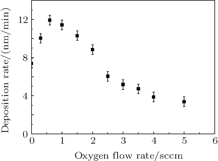 | Fig. 5. Experimental mass deposition rates from Ti-doped V target varying with oxygen flow rate. |
 | Fig. 6. (a) Calculated and (b) measured target voltages versus oxygen flow rate for vanadium targets with Ti inserts and single vanadium target. |
Placing inserts in the racetrack is a common technique to change the thin film composition during reactive magnetron sputtering. In this work, a vanadium target is adapted with Ti pieces. The reactive sputter deposition of Ti-doped VOx is studied by both numerical modeling and experiments at different reactive gas flow rates. The reactive sputtering behaviors of the targets such as target voltage and mass deposition rate can be understood from the sputter yields of the insert material Ti and the host target V.
Results show that the hysteresis curve width is not changed by doping titanium in the vanadium target. By doping titanium in the vanadium target, the average yield decreases, resulting in the reduction of sputtering erosion. Therefore, less gas is needed for the transition from metallic mode to poisoned mode. The variations of ratio between metal V content and metal Ti content with oxygen gas flow rate employed in the numerical model are confirmed by EDX measurements. Results show a reasonable agreement between numerical results and experimental data. With increasing the O2 flow rate, the EDX detected vanadium element concentration decreases, indicating that the vanadium on the target tends to react with oxygen more easily than titanium due to the multi-valence states of vanadium oxide.
| 1 |
|
| 2 |
|
| 3 |
|
| 4 |
|
| 5 |
|
| 6 |
|
| 7 |
|
| 8 |
|
| 9 |
|
| 10 |
|
| 11 |
|
| 12 |
|
| 13 |
|
| 14 |
|
| 15 |
|
| 16 |
|
| 17 |
|