


Charge and spin-dependent thermal efficiency of polythiophene molecular junction in presence of dephasing
[Golsanamlou Z.† , Bagheri Tagani M., Rahimpour Soleimani H.‡]
, Bagheri Tagani M., Rahimpour Soleimani H.‡]
|
|


†Corresponding author. E-mail: zahra.golsanamlou@gmail.com
‡Corresponding author. E-mail: rahimpour@guilan.ac.ir
The charge and spin-dependent thermoelectric properties of different lengths of polythiophene in a molecular junction are investigated using the Büttiker probe method within Green function formalism in linear response regime. The coupling of the molecular chain to three-dimensional ferromagnetic electrodes is described by a tight-binding model for both parallel and antiparallel spin configurations. The decrease of height of transmission probability peaks and thermoelectric coefficients are observed in the presence of the Büttiker probes. The reduction is more intensive in the strong dephased chains. Results show that the spin magnetothermopower is bigger than the charge magnetothermopower due to the larger difference between the spin thermopowers with respect to the charge ones. In addition, we observed that the kind of carriers participating in the thermoelectric transport depends on the number of the thiophene rings.
The dephasing process in molecular systems is an interesting phenomena that has attracted the attention of researchers. Dephasing in real systems can be made of electron– phonon interaction, defects, impurities, etc., which destroy the phase of electrons in the transport mechanism.[1– 5] A well-known way to take into account the dephasing process or inelastic scattering in nanosystems is to use additional Bü ttiker probes.[6] D’ Amato and Pastawski studied the conductance in a disordered linear chain.[7] The chain length was considered to be finite and incoherent scattering processes on a tight-binding (TB) model were studied using Bü ttiker probe model.
Study of charge and spin-dependent thermoelectric properties has become a popular topic in recent years for conversion of induced thermal energy to electric energy.[8, 9] The thermal efficiency depends on dimensionless quantity as a figure of merit, ZT = S2GeT/κ which is a function of thermopower (S), operating temperature (T), electrical and thermal conductances, Ge and κ . The efficiency of the thermoelectric nanodevices to convert a temperature gradient into spin voltage can be determined by spin figure of merit, 
Because of the unique properties of π -conjugated polymers like HOMO-LUMO (highest occupied molecular orbital– lowest unoccupied molecular orbital) gap, spin– orbit coupling, high carrier mobility, low conductivity and easy synthesis, [8, 12– 14] they are mainly considered for thermoelectric studies.[15, 16] One of the famous polymers is polythiophene (PT) with thiophene rings which are in antiposition structure. The stable state of this polymer and maximum conductance are occurred in a flat geometry of the thiophene rings because of the lower HOMO– LUMO gap than twisted one.[17] Also, the electrical conductivity of PT can be increased by n-doping and p-doping agents.[18] Therefore, PT has been selected as a good choice for molecular investigations.[19– 21] The length dependent study of thermoelectric properties has been attracted considerable attention from researchers.[22, 23]
Datta et al.[24] studied a simple phenomenological approach to regard dephasing process in quantum transport models using Green function formalism. They introduced two specific self-energies: one for momentum conservation and the other for momentum relaxation. They found that the first case affects phase relaxation length but the second one affects both phase and momentum relaxation lengths. The multi-terminal electron transport was studied through a single phenalenyl molecule[25] using TB model and Green function formalism. It was observed that the electron transport depends on molecule– electrodes interface geometry, the presence of other electrodes, and the strength of molecular coupling to the side connected electrodes.
In the present work, we study the effect of dephasing on the charge and spin thermoelectric properties of different lengths of PT molecule coupled to the three dimensional ferromagnetic (FM) electrodes using Green function formalism in linear response regime, which has not been reported so far. The outline of this paper is as follows: in Section 2, we describe our theoretical method using Su– Schrieffer– Heeger (SSH) model[26] for Hamiltonian of the PT molecule and TB model for electrode– PT coupling. We account for the dephasing effect in our calculation by Bü ttiker probe method and D’ Amato calculations.[7] Our numerical results are presented in Section 3. Finally a brief conclusion is given at the end of the paper.
We consider the Keldysh nonequilibrium Green function formalism to calculate, respectively, the charge, heat, and spin currents, in presence of dephasing, as follows:[27– 29]


where, fL(R)(ε ) = [1 + exp((ε − μ L)/kTL)]− 1 is the Fermi– Dirac distribution function of electrode L(R), μ L and TL denote the chemical potential and temperature of the electrode L, respectively. Teffσ is the spin-dependent effective transmission coefficient of the disordered system and the total effective transmission coefficient of the carriers is as follows:

where, Teffσ is calculated using the D′ Amato– Pastawski model:[7]
here, the first term on the right-hand side of the above equation describes the coherent transport, whereas the second term describes the transport in the presence of the phase breaking process. Wkmσ is given as

where, the reflection probability, Rkkσ , and transmission probability, Tkmσ are:


where, Γ k, σ are the spin-dependent broadening functions of the fictitious electrodes and are the same for all atomic sites in the chain.
The retarded Green function of the PT molecule coupled to the FM electrodes (Fig. 1(a) in presence of dephasing is written as follows:
where, 0+ is an infinitesimal value. Hm denotes the Hamiltonian of the molecule via an extended SSH model:[30, 31]
Here, ε i is the on-site energy and VG refers to the gate voltage used to tune the molecular energy levels. 

where, t1, t0, and α are the non-degeneracy parameter, zero displacement hopping integral, and electron-lattice coupling constant, respectively.[33] To obtain ui, the Schrö dinger equation can be solved for the electronic part of the Hamiltonian to find the electronic eigenstates 

where,
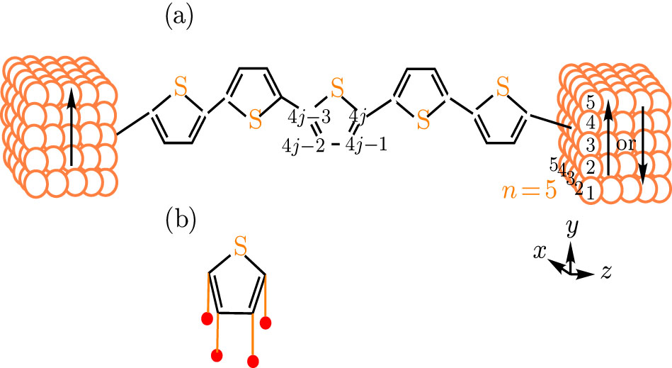 | Fig. 1. (a) The FM/polythiophene/FM junction in both parallel and antiparallel configurations. Here, n refers to the number of thiophene rings and 4j, … , 4j − 3 denote to the site of carbon atoms in molecular chain. (b) Each carbon site of PT molecule is assumed to be coupled to a fictitious electronic reservoir to include the dephasing process. |
The displacement of ith carbon atom can be determined by minimizing the total energy of the system;
Equations (9) and (11) should be solved in a self-consistent manner. Our model describes the π -electron system of the PT connected to the semi-infinite FM electrodes with a simple cubic structure. The electrodes have a square cross section (x– y plane) because the electron transport happens through the central point at the cross section connected to the end of the molecular chain, see Fig. 1(a). Hα indicates the Hamiltonian of the α (= L or R) FM electrode, which is written as:

where, 

where, tc(i, σ , k) = tc is the coupling parameter between PT molecule and FM electrodes.
Other parameters in Eq. 6 can be described as: Σ α , σ (ε ) is the spin-dependent self-energy function that describes the effect of semi-infinite FM electrodes on the molecular chain and is defined as: 

where, ri ≡ (xi, yi, zi), K ≡ (lx, ly, kz), z = ε 0 + i0+ ,
and
Here, lx, y(= l, … , Nx, y) are integers, kz ∈ [− π /a, π /a], and Nβ (β = x, y, z) is the number of lattice sites in β direction. Nx and Ny denote the number of atoms at the cross section of the FM electrodes, ε 0 is the on-site energy in the electrodes and will be set to t and t is the hopping strength between the nearest neighbor sites in the electrodes. τ α , c is the coupling matrix and is non-zero only for the near neighbor points in the molecule and the electrode α . Following the Bü ttiker probe method, the effect of dephasing is modeled phenomenologically by coupling each carbon site to one fictitious electron reservoir, as indicated in Fig. 1(b). We assume that the net current flowing through these probes is zero, so the electron transport remains elastic although incoherent and currents (Eqs. (1a)– (1c)) could be expressed by the formula similar to the Landauer formula.[36] Therefore, the fictitious probes can be affected in our system through a scattering self-energy term, as follows:[37]
Here, N refers to the number of carbon atoms in the molecular chain. The coupling terms Γ L, σ and Γ R, σ can be calculated through the expression[38]

where, advanced self-energy 
In order to compute the charge and spin thermoelectric properties of the PT molecular junction in the linear response regime, the charge, heat and spin currents are expanded by temperature gradient, Δ T, and induced voltage drop, Δ V, to first order as follows:


where

The charge and spin thermoelectric coefficients are given as follows:[39, 40] the ratio of the induced voltage drop to applied temperature gradient is charge thermopower, S, when the J = 0. Also, spin thermopower, Ss is the ratio of the induced spin voltage drop to the applied temperature gradient when the charge and spin currents vanish (J = 0 and Js = 0), therefore,

and

are charge and spin thermopowers, respectively. The spin dependent thermopower is given as

The spin and charge conductances (Gs and Ge, respectively) are given by:


Finally, the thermal conductance, κ , is as follows:
In this section, we describe the numerical results for disordered PT chain connected to FM electrodes. The direction of magnetization in the left FM electrode is fixed in the + y direction while the magnetization in the right electrode is free to flip into either the + y direction, parallel (P) configuration or − y direction, antiparallel (AP) configuration, see Fig. 1(a). We set | Jα | = 1.5 eV, t = 1 eV, ε 0 = 1 eV for the FM electrodes.[37] For PT molecular chain, we have K0 = 21 eV/Å 2, ε j = – 4.3 eV, t0 = 2.5 eV, t1 = 0.675 eV, ε s = ts = 0.05t0, α = 4.3 eV/Å .[32] Also, we regard T = 11 K, tc = 0.5 eV, γ = 0.005 eV, and Ef = 0. In this study, the temperature is low enough to consider the no spin-flip process.
Figure 2 shows the dependence of the charge thermoelectric properties on the gate voltage for the PT molecule with five rings in presence and absence of the fictitious probes in parallel configuration. It is obvious from Fig. 2(a) that by increasing γ , Ge decreases. It can be found from the effective transmission coefficient of the junction. One can see from the inset of Fig. 2(a) that the height of Teff(ε ) peak decreases in the presence of dephasing due to increase of resistance to charge transport because of the enhanced probability to backscatter the charge via fictitious probes.[2] It is also observed from the inset of Fig. 2(a) that the peak of transmission probability becomes wider in the presence of additional probes (γ ≠ 0) in comparison with γ = 0. This broadening arises from the dominance of the randomizing effect over backscattering as a consequence of phase incoherency in the dephasing process.[29] Because of the better clarity, we indicate only one of the Teff(ε ) peaks in the inset of Fig. 2(a). The peak becomes wider and its height decreases by increasing γ due to more scattering rate.
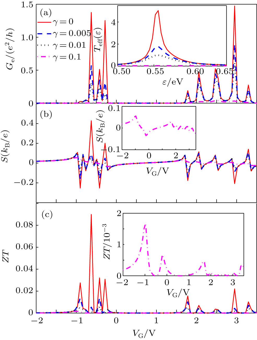 | Fig. 2. The charge thermoelectric properties of PT (n = 5) for different γ : (a) electrical conductance, (b) charge thermopower, (c) charge figure of merit. The insets show (a) the effective transmission coefficient for different γ , (b) charge thermopower in γ = 0.1 eV, (c) charge figure of merit in γ = 0.1 eV. T = 11 K and Ef = 0. |
The charge thermopower and figure of merit are indicated in Figs. 2(b) and 2(c). The thermopower of PT has an oscillating behavior, denoting the change in the number of electrons in the molecular energy levels[41– 43] and decreases in the presence of dephasing. The value of S decreases more by γ because of of the larger scattering in atomic sites of the molecular chain. In the strong coupling regime, the number of oscillation of the peaks decreases because the Teff(ε ) peaks almost disappear in the greater value of γ . The main factor for the shape of ZT is charge thermopower. The ZT is zero in points that S = 0 and the extremum points of S are the extremums of ZT. Therefore, the value of the ZT decreases by increasing γ .
The electrical and spin conductances in the presence of the additional probes for three consecutive lengths of PT chain (n = 5, 6, and 7) are indicated in Fig. 3 versus gate voltage in both P and AP configurations. The conductance peaks are located in the molecular energy levels and their height decreases by increasing molecular length. It can be found from the change in the effective transmission coefficient. The HOMO– LUMO gap slightly decreases by the chain length enhancement. This comes from the change in the arrangement of the π -electron levels of the molecule by increasing the molecular length due to electron-donating characteristic of sulfur atoms in thiophene rings.[44, 45] Figures 3(a) and 3(b) show the electrical conductance in P and AP configurations of the electrodes, respectively. The value of Ge in P configuration is more than the AP one because the electrical conductance in P configuration is controlled by participating tunneling between majority and minority carriers in both FM electrodes. Meanwhile, in the AP alignment the magnetic moments of leads are in the opposite direction and the carriers have to tunnel between the spin-majority and spin-minority bands through the molecular levels; consequently, the charge transport is suppressed. Therefore, the values of both electrical and spin conductances decrease in AP alignment. The spin conductance is the difference between spin-up conductance, G↑ , and spin-down conductance, G↓ . In the P configuration, Gs has a positive value for all considered lengths (Fig. 3(c), indicating that the spin-up conductance is bigger than spin-down one. But in the AP configuration, the Gs value is positive in some gate voltages and in some gate voltages is negative, denoting that in the negative case G↓ has bigger value than G↑ (See the inset of Fig. 3). It is interesting that the value of Gs in AP alignment is much less than in the P alignment because of the larger suppression in the charge transport between electrodes.
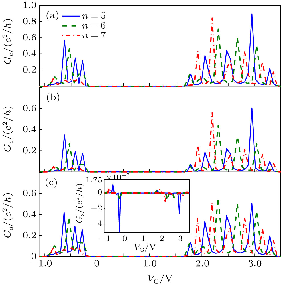 | Fig. 3. Electrical conductance in (a) P and (b) AP configurations, (c) spin conductance in P configuration, versus gate voltage. The inset of panel (c) shows Gs in antiparallel alignment. T = 11 K and Ef = 0. |
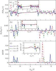
The charge and spin thermopowers as a function of the gate voltage are indicated in Figs. 4(a) and 4(b) for considered lengths of the disordered PT chain. Figure 4(a) and its inset show the charge thermopower in P and AP configurations, respectively. The value and the number of oscillations increase by molecular length enhancement in both configurations.[22, 46] It can be found from the increasing number of π -electrons in the PT chain that increasing the molecular length causes the number of electrons tunneling through the molecular level to increase. The thermopower (charge and spin) is zero in resonance energies and electron– hole symmetry points. In the symmetry points, both carriers participating in transport mechanism, have equal contributions but with opposite signs, so the net induced voltage drop is zero and, as a consequence, thermopower becomes zero. In resonance energies, the temperature gradient cannot produce a net electrical current because the electrons can tunnel from the hotter and colder electrodes to the molecular levels without needing thermal energy. The spin thermopower in both P and AP configurations is represented in Fig. 4(b) and its inset, respectively. Ss is employed to study the spin effects in the thermoelectric transport, and is the difference between spin-up and spin-down thermopowers, S↑ − S↓ . Similar to charge thermopower, the spin thermopower changes the sign and magnitude with molecular length alternatively when the Fermi level crosses the resonance energy or symmetry points.[10] The positive sign of Ss indicates that the S↑ is greater than the S↓ . In fact, the induced spin-up voltage drop is bigger than spin-down one and the negative sign of spin thermopower denotes S↓ > S↑ , whereas the sign of charge thermopower determines the kind of carriers participating in energy and charge transports. It is obvious from the Figs. 4(a) and 4(b) that the sign of charge thermopower is the opposite of the spin thermopower due to the increase of the minority spin voltage.[42, 47] Also, the values of both S and Ss are decreased in AP configuration with respect to the P configuration due to tunneling between spin-majority and spin-minority carriers and the suppressed transport. The reduction is more obvious in the case of Ss.
 | Fig. 4. (a) Charge thermopower in P configuration versus gate voltage. The inset shows the charge thermopower in the AP configuration. (b) Spin thermopower as a function of gate voltage in P configuration, the inset shows the Ss in AP one. (c) The charge magnetothermopower and inset shows the spin magnetothermopower versus gate voltage. T = 11 K and Ef = 0. |
The charge thermal tunneling effect from FM electrodes to the molecular levels due to the temperature gradient results in charge magnetothermopower (MTP). On the other hand, the spin thermal tunneling due to spin voltage drop results in spin magnetothermopower (SMTP). These quantities are related to the dependence of the charge and spin thermoelectric effects on the magnetic orientation of the electrodes and are defined as:[48] MTP = (S(P) − S(AP))/(S(AP)) and SMTP = (Ss(P) − Ss(AP))/(Ss(AP)). The MTP of the different lengths of the PT chain is indicated in Fig. 4(c) versus gate voltage. It is observed from this figure that, the thermal tunneling between carrier bands for n = 7 is larger than other lengths in VG = 2.2 V but in negative gate voltages the MTP (tunneling) is nearly zero. In the case of PT with five rings, the tunneling effect is intensive in VG = − 1 V to VG = 0, and VG = 3 V. Also, the thermal tunneling effect can be observed in almost all the molecular energy levels. The gate voltage dependence of SMTP for the considered lengths is shown in the inset of Fig. 4(c). The spin thermal tunneling effect is more significant in the case of n = 6 with respect to other lengths. The value of the SMTP is greater than MTP due to existence of big difference between spin thermopowers in parallel and antiparallel configurations.
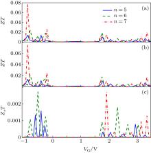
The figure of merit of the considered lengths of the molecule for P and AP alignments is indicated in Figs. 5(a) and 5(b) versus gate voltage. The number and magnitude of the ZT peaks increase by increasing the molecular length because the same behavior was observed for S in the same configuration. The dependence of the spin figure of merit on the gate voltage for P configuration is plotted in Fig. 5(c). The peaks of ZsT are in the points that Ss has extremum and the valleys of it are placed at points that Ss = 0. The value of ZsT in AP configuration is considerably less than P one and is near to zero.
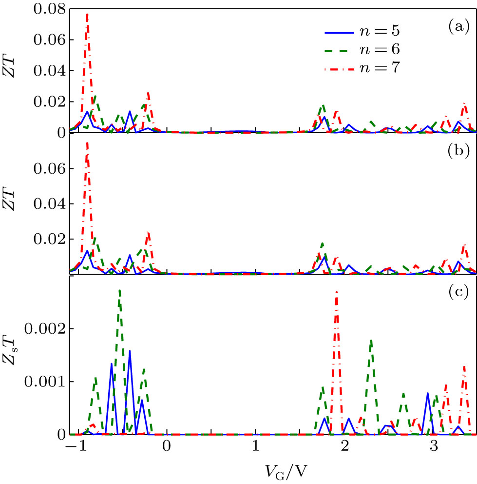 | Fig. 5. Charge figure of merit in (a) parallel and (b) antiparallel configurations. (c) Spin figure of merit for P configuration versus gate voltage. T = 11 K and Ef = 0. |
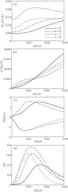
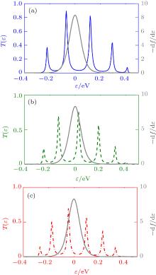
The temperature dependence of the charge thermoelectric properties for the different disordered molecular lengths are shown for P configurations in Fig. 6. The electrical conductance increases by the length due to decreasing the HOMO– LUMO gap and the distance of energy levels (see Fig. 6(a). It causes the number of tunneling electrons to increase. The electrical conductance increases by the temperature in each length of the molecular chain. The effective transmission coefficient is independent of the temperature but the Fermi derivative is temperature dependent. By increasing the temperature, (− ∂ f / ∂ ε ) is broadened and more parts of Teff(ε ) can be covered by (− ∂ f / ∂ ε ), so the number of electrons participating in transport increases. The magnitude of Ge for PT molecule with six thiophene rings is bigger than other considered PT lengths. It can be found from the Figs. 7(a)– 7(c) that the Teff(ε ) peaks are more included in (− ∂ f / ∂ ε ) for n = 6 with respect to the other lengths (n = 5 and n = 7). Therefore, the number of tunneling carriers increases and Ge becomes bigger than the others.
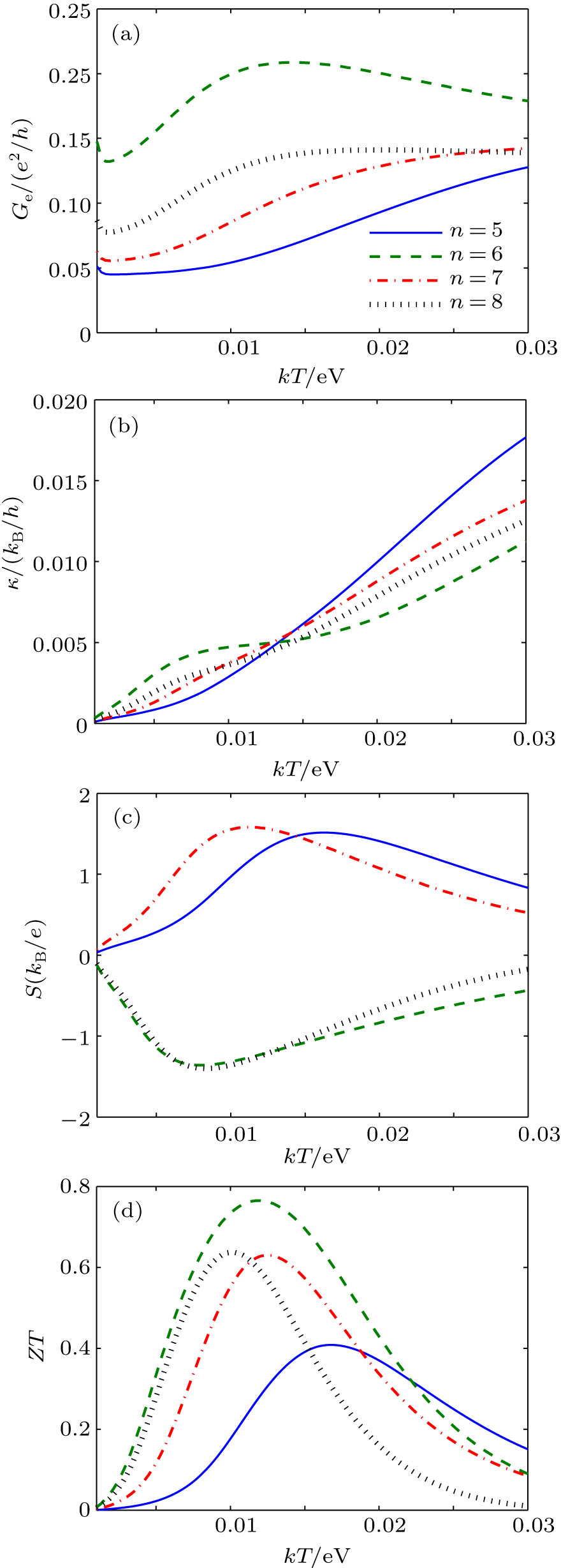 | Fig. 6. Charge thermoelectric coefficients versus temperature for different lengths of disordered polythiophene chain in P alignment: (a) electrical conductance, (b) thermal conductance, (c) charge thermopower, and (d) charge figure of merit. We set VG = 0 and Ef = 0. |
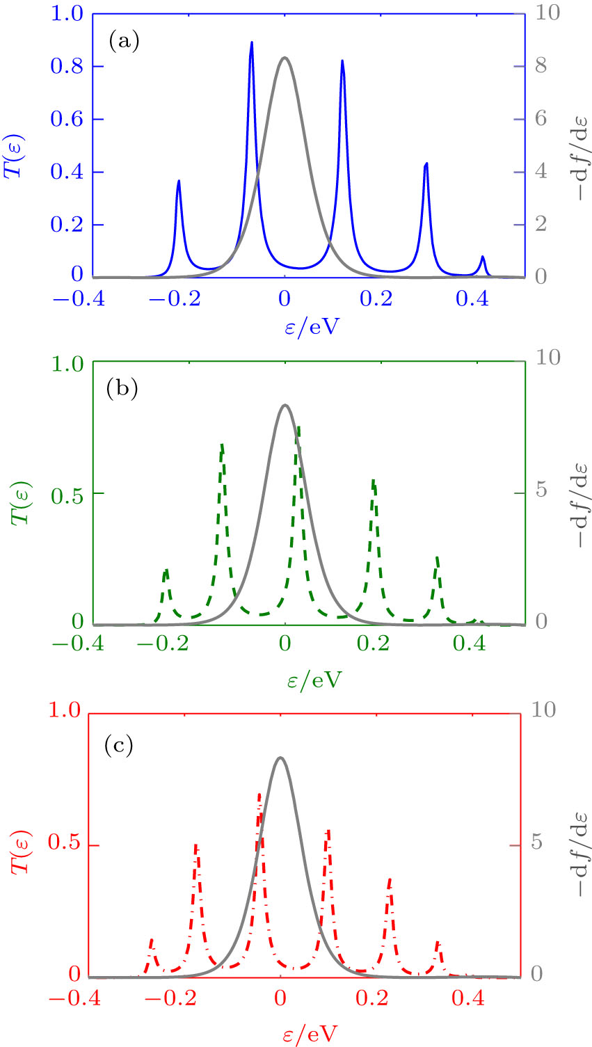 | Fig. 7. Transmission coefficient peaks in (a) n = 5, (b) n = 6, and (c) n = 7. The Fermi derivative is indicated in gray. |
The thermal conductance versus temperature is shown Fig. 6(b) for different lengths of the PT molecular chain. It is obvious that the n = 5 has maximum value for κ with respect to other lengths. Figure 6(c) indicates the charge thermopower as a function of temperature. As mentioned in the description of Fig. 4, the sign of charge thermopower shows the kind of carrier participating in the transport mechanism. For the molecular chain with even number of thiophene rings, S is negative, indicating that the electrons are responsible for energy and charge transports in the chain, also, the Fermi level is located near to LUMO level. Whereas, the sign of S for odd number of thiophene rings shows that the holes are dominant for the transport mechanism in the junction and the Fermi level is located near to HOMO level.
The temperature dependence of the charge figure of merit for the considered lengths of disordered chain is shown in Fig. 6(d). The ZT reaches to a maximum and then decreases by the temperature enhancement. This can be found from the curve of S. The maximum value of the ZT almost increases by increase of the thiophene rings. In the case of n = 6, ZT has maximum value in comparison with other consecutive lengths, because the Ge is maximum and κ is minimum for n = 6. The same behaviors are observed in AP configuration but the value of the coefficients is decreased due to the suppression of transport in this alignment.
In this work, we have studied the charge and spin thermoelectric properties of polythiophene molecular junction with ferromagnetic electrodes in both parallel and antiparallel configurations. We have introduced the dephasing process with a phenomenological Bü ttiker probe model. Our method is based on a tight-binding model within Green function formalism that can help to find the charge and spin thermoelectric coefficients of a disordered PT chain in the linear response regime. Our results show the decrease of thermoelectric coefficients in both configurations is due to the decrease of height and increase of wide of effective transmission coefficient peaks. By increasing incoherency, the decrease is more obvious. We have also found that the SMTP versus energy levels is greater than MTP (charge thermal tunneling) due to big difference between spin thermopowers in parallel and antiparallel alignments respect to charge thermopower. In addition, the sign of thermopower is affected by the number of thiophene rings in the chain. Therefore, the kind of carrier controlling transport also changes.
| 1 |
|
| 2 |
|
| 3 |
|
| 4 |
|
| 5 |
|
| 6 |
|
| 7 |
|
| 8 |
|
| 9 |
|
| 10 |
|
| 11 |
|
| 12 |
|
| 13 |
|
| 14 |
|
| 15 |
|
| 16 |
|
| 17 |
|
| 18 |
|
| 19 |
|
| 20 |
|
| 21 |
|
| 22 |
|
| 23 |
|
| 24 |
|
| 25 |
|
| 26 |
|
| 27 |
|
| 28 |
|
| 29 |
|
| 30 |
|
| 31 |
|
| 32 |
|
| 33 |
|
| 34 |
|
| 35 |
|
| 36 |
|
| 37 |
|
| 38 |
|
| 39 |
|
| 40 |
|
| 41 |
|
| 42 |
|
| 43 |
|
| 44 |
|
| 45 |
|
| 46 |
|
| 47 |
|
| 48 |
|