

Pattern transition from nanohoneycomb to nanograss on germanium by gallium ion bombardment*
[Zheng Xiao-Hua) , Zhang Miaoa) , Huang An-Pingb) , Xiao Zhi-Songb) , Paul K Chuc) , Wang Xia) , Di Zeng-Fenga)†  ]
]
]
 |


†Corresponding author. E-mail: zfdi@mail.sim.ac.cn
*Project supported by the National Natural Science Funds for Excellent Young Scholar, China (Grant No. 51222211), the National Natural Science Foundation of China (Grant Nos. 61176001 and 61006088), the National Basic Research Program of China (Grant No. 2010CB832906), the Pujiang Talent Project of Shanghai, China (Grant No. 11PJ1411700), the Hong Kong Research Grants Council (RGC) General Research Funds (GRF), China (Grant No. 112212), the City University of Hong Kong of Hong Kong Applied Research Grant (ARG), China (Grant No. 9667066), and the International Collaboration and Innovation Program on High Mobility Materials Engineering of Chinese Academy of Sciences.
During the irradiation of Ge surface with Ga+ ions up to 1017 ions·cm−2, various patterns from ordered honeycomb to nanograss structure appear to be decided by the ion beam energy. The resulting surface morphologies have been studied by scanning electron microscopy and atomic force microscopy. For high energy Ga+ irradiation (16–30 keV), by controlling the ion fluence, we have captured that the equilibrium nanograss morphology also originates from the ordered honeycomb structure. When honeycomb holes are formed by ion erosion, heterogeneous distribution of the deposited energy along the holes leads to viscous flow from the bottom to the plateau. Redistribution of target atoms results in the growth of protuberances on the plateau, and finally the pattern evolution from honeycomb to nanograss with an equilibrium condition.
Self-organization during low-energy ion irradiation has aroused much interest for application in sublithographic surface template, for quantum dot device and photoelectric device fabrication.[1– 6] Ripples, [2, 7] dots, [8– 11] and even ultra-ordered honeycomb like lattice of graphene[12] have been reported on various of material surface. Recently, more diversified morphologies formed on Ge surface influenced by the kinds of incident ion, [13, 14] irradiation angles, [15] substrate temperature, [16] kinetic energy[12] have been reported. Thus, it is of great interest to develop the working model to predict and understand the surface behaviors under ion bombardment. It is generally considered the origin of patterns on materials surface is attributed to an interplay of surface instability due to sputtering and mass redistribution together with surface relaxation mechanisms.[17, 18] Models based on ion erosion, surface diffusion, mass redistribution and viscous flow effects have been investigated widely, [19– 22] and recently, are introduced to understand the patterns on Ge.[14, 23] However, the surface behaviors are complicated and there are many issues, particularly, no direct experimental verifications of such pattern transitions evolution with ion energy (from honeycomb ordered holes to porous structure on morphology) so far. In this work, we take care to identify and confine our experimental study to the initial stage of Ga+ ion irradiation of Ge with particular ion beam energy and observe the transition process from the honeycomb ordered holes to porous morphology. Such a transition process illustrates that in addition to ion beam erosion, the viscous flow induced atomic redistribution effect is responsible the evolution of surface morphology. A model which takes into account both effects is proposed to describe the morphological transition under the condition of Ga+ bombardment. The results are helpful to understand and make potential to control the nanostructures on Ge.
Ge (100) wafers were irradiated by a Ga+ beam at a normal angle on the Helios Nanolab 600 station equipped with both focused ion beam (FIB) and scanning electron microscopy (SEM) at a vacuum of 5.71× 10− 4 Pa. The bombarded area was 10× 10 μ m2. Ga+ ion energy was varied from 5 keV to 30 keV and the flux was 6× 1014 cm− 2· s− 1. Surface morphology of Ge was characterized by in situ SEM and ex situ atomic force microscopy (AFM) which was conducted in the tapping mode using a probe coated with Cr and Au with a spike radius of less than 10 nm.
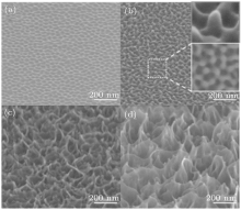
The dependence of the surface morphology of Ge on ion beam energy is shown in Fig. 1. The implantation dose is about 3× 1017 cm− 2 with all kinds of pattern. This ion dose is sufficient to produce equilibrium surface morphology. It means that even more Ga+ irradiation on Ge with the same beam energy will not change the morphology. Thus, difference of the patterns is decided only by the ion beam energy. For 5-keV Ga+ ion irradiation, an ordered honeycomb structure can be observed in Fig. 1(a). Similar to a polycrystalline structure, large domains of perfect hexagons are separated by line defects. The mean diameter and spacing of the honeycomb holes are 33 nm and 50 nm, respectively, which agree with previous data by Ga+ irradiation.[12] When the ion beam energy is increased to 8 keV, the surface roughness increases and some protuberances emerge as shown in the inset marked with the red circle in Fig. 1(b). The protuberances are not arranged regularly, but rather along the edge of the hexagonal holes. It can be observed in the SEM image obtained with an electron beam vertical to the sample shown in the inset in Fig. 1(b) marked with the white square. By further increasing the ion energy to 16 keV, the protuberances start to morph into a grass-like structure as shown in Fig. 1(c). This structure is called nanograss here which is also called porous structure in other works. As shown in Fig. 1(d), when the ion bombardment energy is raised to 30 keV, the nanograss morphology becomes more pronounced as manifested by the larger depth and higher porosity.
 | Fig. 1. SEM images of nanostructures induced by focused Ga ion beam bombardment of Ge at different energies: (a) 5 keV, (b) 8 keV, (c) 16 keV, and (d) 30 keV. Photographs are obtained with a tilt angle of 54° between the electron beam and the samples. Inset of panel (b) depicts zoom-in image of the protuberance formation. |
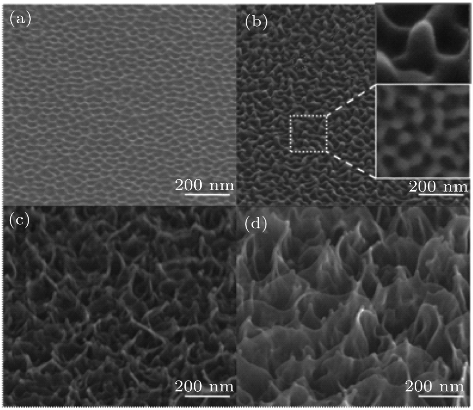
In order to study the topographical transition from the virgin surface to nanograss, the kinetic energy of Ga+ is fixed at 16 keV and the ion dose is increased from 5× 10¹⁵ to 1× 1016 cm− 2, gradually. In the initial stage corresponding to an ion dose of 5× 1015 cm− 2, the surface becomes rougher and some pits are formed as shown in Fig. 2(a), indicating that Ga+ ions induce instability on the Ge surface. This is in accordance with Sigmund’ s[24] model that the ion impact can create instability and increase the roughness of a surface. In his model, the sputtering yield depends on the surface curvature and troughs are eroded more rapidly than crests.[24] As ion beam sputtering proceeds corresponding to an ion dose of 6× 1015 cm− 2, randomly distributed pits morph into the ordered honeycomb structure as shown in Fig. 2(b). It should be noted that this morphology is similar to the equilibrium pattern produced by 1× 1017 cm− 2 5 keV Ga+ ion bombardment shown in Fig. 1(a). The honeycomb is formed as a result of the isotropic effect of ion irradiation as described by the damped Kuramoto– Sivashinsky (DKS) model.[20, 22] However, the ordered honeycomb is not the equilibrium morphology under the beam energy of 16 keV and some protuberances emerge along the edge of each hole of the honeycomb structure when the ion dose is increased to 7× 1015 cm− 2, as shown in Fig. 2(c). It evolves into the morphology as shown in Fig. 1(b). The growth of the protuberance becomes more prominent as the ion beam irradiation continues (Fig. 2(d)) finally producing the nanograss morphology as previously shown in Fig. 1(c). Our data depict an evolution process of Ge morphology under 16 keV Ga+ beam and provide a direct evidence that the nanograss formed under high ion beam energy evolves from the ordered honeycomb structure at the beginning of Ga+ ion bombardment, and then saturated.
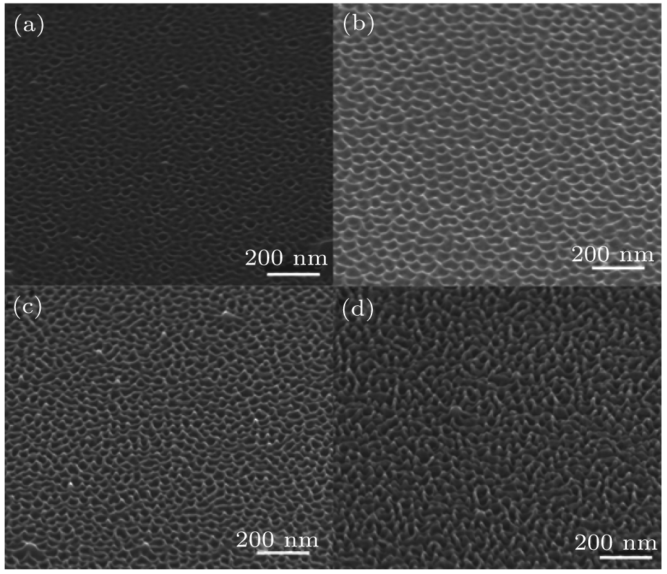 | Fig. 2. SEM images of nanostructures on the surface of Ge formed by 16 keV Ga+ bombardment with different ion doses: (a) 5× 1015 cm− 2, (b) 6× 1015 cm− 2, (c) 7× 1015 cm− 2, and (d) 1× 1016 cm− 2. All photographs are obtained with a tilt angle of 54° between electron beam and the sample. |
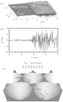
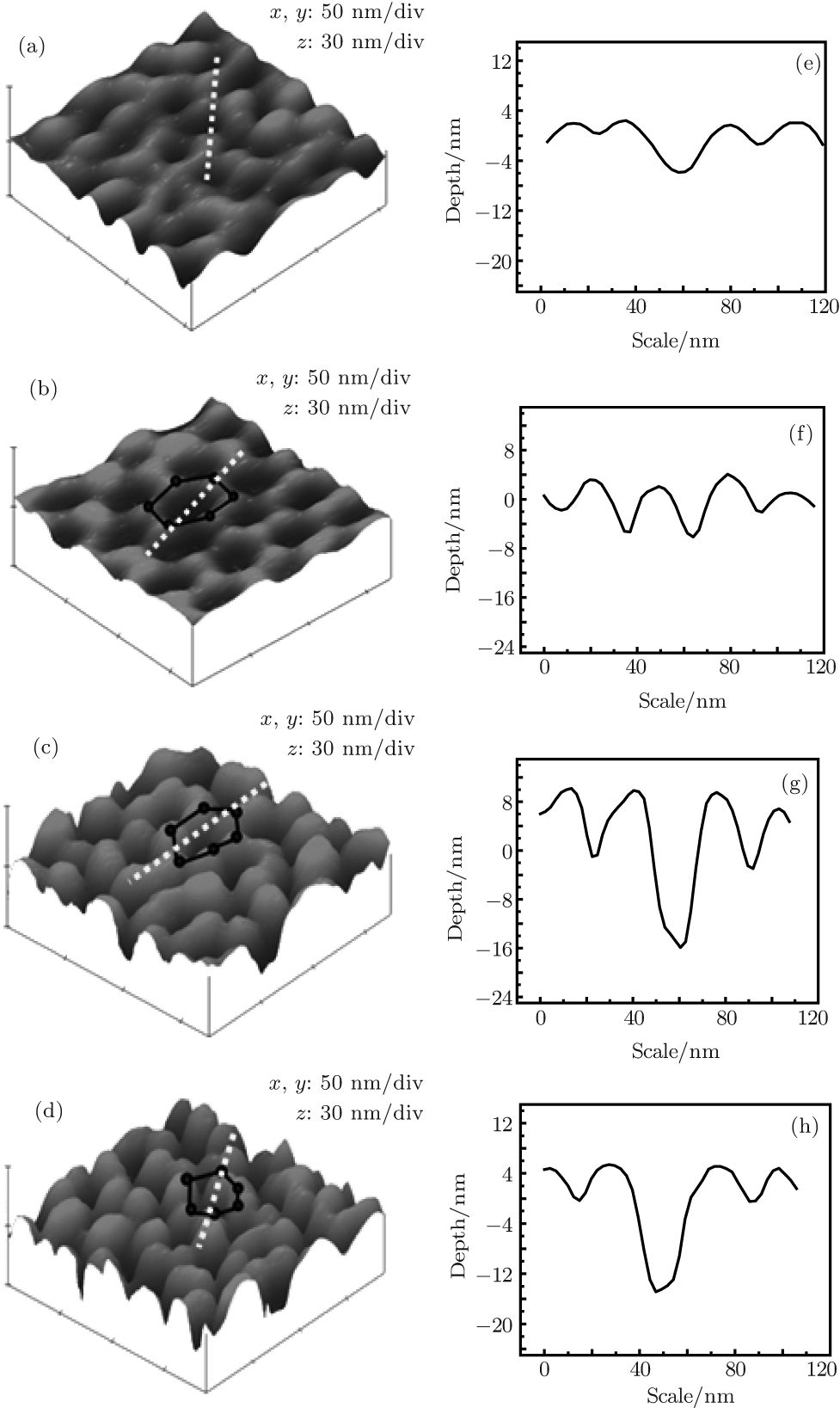 | Fig. 3. AFM images of the fluence-dependent surface morphology after irradition with 16 keV Ga+ and different ion doses: (a) 5× 1015 cm− 2, (b) 6× 1015 cm− 2, (c) 7× 1015 cm− 2, and (d) 1× 1016 cm− 2. Panels (e)– (h) display the profile acquired along the dashed lines in panels (a)– (d), respectively. It demonstrates the deepening of the hole and the growing of the shoulder during the ion bombardment. |
In order to elucidate the underlying mechanism responsible for the evolution from the honeycomb structure to nanograss, the surface morphology is further characterized by AFM. 3D (three-dimensional) AFM images are represented in Figs. 3(a)– 3(d), and the corresponding line scans along the long diagonals of the honeycomb holes are depicted in Figs. 3(e)– 3(h) as marked by the dashed lines in Figs. 3(a)– 3(d). In the initial stage associated with a Ga+ dose of 5× 1015 cm− 2, the surface becomes unstable and some irregular pits begin to form due to ion erosion as shown in Fig. 3(a). This observation is consistent with the SEM results in Fig. 2(a). No apparent order is observed in this stage and the corresponding line scan does not exhibit any regularity, as shown in Fig. 3(e). As ion beam irradiation continues, an ordered honeycomb structure is formed as shown in Fig. 3(b). Each hole of the honeycomb structure is embraced by six protuberances marked by the circles and connecting lines in Fig. 3(b). The protuberances are arranged orderly and the mean height is about 4 nm as shown in Fig. 3(f). The behavior cannot be explained by erosion alone and mass redistribution should takes place at this stage. As ion bombardment proceeds further, the protuberances remain at the same position but become more prominent as shown in Figs. 3(c) and 3(d). The average heights of the protuberances increase to 6 nm and 10 nm as well as the deep of the hole, respectively, as shown in Figs. 3(g) and 3(h), resulting in the appearance of the nanograss morphology. The results indicate that if mass redistribution induces growth of the protuberances it must be orientated by a driving force.
Further evidence is obtained when comparing the irradiated and control samples, as shown in Fig. 4(a). The irradiation is accomplished in an instant with much higher ion beam intensity. Sputtering effect to the whole irradiated area can be ignored. Therefore, the profile of irradiated area can be referred to the unirradiated area. Profile of the section is measured as marked by the dashed line in Fig. 4(a) and represented in Fig. 4(b). The valleys of the line scans are lower than the original surface (unirradiated area), whereas the peaks are several nanometers higher than the original surface. The formation of valleys in the irradiated area can be attributed to erosion easily, but the appearance growth of the protuberances is mainly due to impact-induced atomic redistribution. It can be as direct evidence that mass redistribution is important for the morphology transition. Based on the observations shown above, a model is proposed to analyze driving force of the atomic redistribution and to explain the morphological evolution. Initially, pits are formed by Ga+ impact. Due to isotropic effect of ion irradiation, pits are ordered arranged as the honeycomb. When the ordered honeycomb structure is bombarded by Ga+ continually, the incoming ions penetrate the pit and the process is denoted as I schematically presented in Fig. 4(c). During the slowing down of the penetration, generally by nuclear collision process, the kinetic energy of the incident ions will transfer to atoms of the target. The energy transfer process is denoted as II. Based on Sigmud’ s sputtering theory, the energy distribution on the incident surface should depend on the surface curvature and follow a Gaussian distribution.[24] In this case, the atoms at the bottom of the hole will obtain higher energy than those along the sidewall. Plateau surrounded by three neighboring holes has the negative curvature. Thus, it receives the minimum energy. The atoms located in the region deposited with higher energy are inclined to migrate to the plateau. Therefore, viscous flow is formed along the sidewall with energy gradient as a driving force, meanwhile, target atoms are redistributed from the bottom of the hole to the plateau denoted as III. If the target atoms still have sufficient energy after redistribution, they may escape from the plateau region as sputtering process denoted as V, otherwise they will accumulate in area IV forming the protuberances. It is noted that target atoms from three neighboring hexagonal holes contribute to the growth of one protuberance which is embraced by these three neighboring holes. As ion irradiation proceeds, the protuberances grow thus resulting in the morphological transition from the ordered honeycomb structure to nanograss as presents in AFM results. When the sputtering rate of the protuberance is equal to the accumulation rate of the redistributed target atoms, the height of the protuberances is stabilized forming the equilibrium surface morphology. Since both ion erosion and atomic redistribution depend on the incident ion energy, the final surface morphology changes with the ion beam energy.
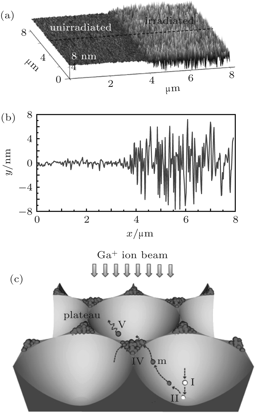 | Fig. 4. (a) Comparison of AFM morphologies between the irradiated and control (not irradiated) samples. (b) Line scan acquired along the dashed line marked in panel (a). (c) Schematic diagram illustrating the morphorlogical evolution from the ordered honeycomb structure to nanograss. |
In conclusion, the morphological evolution of Ga+ ion irradiation-induced pattern on Ge substrate has been investigated. For Ga+ irradiation with low energy, a highly ordered honeycomb structure is formed on Ge surface, but Ga+ irradiation with high energy results in the formation of the nanograss pattern. Furthermore, even for high energy ion irradiation, the nanograss pattern originates from the ordered honeycomb structure at the early stage of ion irradiation. A model incorporated the viscous flow induced redistribution effect and the ion erosion effect has been proposed to interpret the surface morphology evolution from ordered honeycomb structure to nanograss pattern. The results are helpful to understand and control the self-organization nanostructures on Ge surface.
| 1 |
|
| 2 |
|
| 3 |
|
| 4 |
|
| 5 |
|
| 6 |
|
| 7 |
|
| 8 |
|
| 9 |
|
| 10 |
|
| 11 |
|
| 12 |
|
| 13 |
|
| 14 |
|
| 15 |
|
| 16 |
|
| 17 |
|
| 18 |
|
| 19 |
|
| 20 |
|
| 21 |
|
| 22 |
|
| 23 |
|
| 24 |
|