Tuning hybrid liquid/solid electrolytes by lowering Li salt concentration for lithium batteries*

Project supported by the National Key Basic Research Program of China (Grant No. 2014CB932400), the National Natural Science Foundation of China (Grant No. 51772167), the China Postdoctoral Science Foundation (Grant No. 2016M591169), and the Shenzhen Municipal Basic Research Project, China (Grant No. JCYJ20170412171311288).

Yang Wei1, Wang Qi-Di1, Lei Yu1, Wan Zi-Pei1, Qin Lei1, Yu Wei1, Liu Ru-Liang1, 2, Zhai Deng-Yun1, Li Hong3, Li Bao-Hua1, Kang Fei-Yu1, †
Advanced Materials Institute, Graduate School at Shenzhen, Tsinghua University, Shenzhen 518055, China
Materials Science Institute, PCFM Laboratory and GDHPPC Laboratory, School of Chemistry, Sun Yat-sen University, Guangzhou 510275, China
Beijing National Laboratory for Condensed Matter Physics, Institute of Physics, Chinese Academy of Sciences, Beijing 100190, China


† Corresponding author. E-mail: fykang@sz.tsinghua.edu.cn

Project supported by the National Key Basic Research Program of China (Grant No. 2014CB932400), the National Natural Science Foundation of China (Grant No. 51772167), the China Postdoctoral Science Foundation (Grant No. 2016M591169), and the Shenzhen Municipal Basic Research Project, China (Grant No. JCYJ20170412171311288).

Abstract

Hybrid liquid/solid electrolytes (HLSEs) consisting of conventional organic liquid electrolyte (LE), polyacrylonitrile (PAN), and ceramic lithium ion conductor Li1.5Al0.5Ge1.5(PO4)3 (LAGP) are proposed and investigated. The HLSE has a high ionic conductivity of over 2.25 × 10⁻³ S/cm at 25 °C, and an extended electrochemical window of up to 4.8 V versus Li/Li+. The Li|HLSE|Li symmetric cells and Li|HLSE|LiFePO4 cells exhibit small interfacial area specific resistances (ASRs) comparable to that of LE while much smaller than that of ceramic LAGP electrolyte, and excellent performance at room temperature. Bis(trifluoromethane sulfonimide) salt in HLSE significantly affects the properties and electrochemical behaviors. Side reactions can be effectively suppressed by lowering the concentration of Li salt. It is a feasible strategy for pursuing the high energy density batteries with higher safety.

1. Introduction

Lithium ion battery (LIB) has significantly revolutionized our world since its appearance.[1] Further advancement of LIB requires the electrode materials with high energy densities.[2] Lithium metal is an ideal anode choice because of its extraordinarily high theoretical specific capacity (3860 mAh/g), the lowest redox potential (−3.04 V), and the lightest weight (0.59 g/cm3). However, non-uniform deposition, large volume variation and dendrite formation lead to low Coulombic efficiency, shortened lifespan, and serious safety in organic liquid electrolyte when Li metal is used.[3,4] All solid-state batteries adopting solid-state electrolytes are considered to be a promising solution.[59] Nevertheless, poor solid-solid contact between electrolyte-electrode interfaces and particles in electrodes result in such large interfacial resistance that all solid-state batteries can hardly work.[10] Strain and stress produced during cycling further aggravate this dilemma.[11] Many efforts were devoted to improving the electrode-electrolyte interfacial contact. Modifying the surface of the ceramic electrolyte or electrode surface can effectively reduce the interfacial resistance but it only partially solves the problem, and is still far from practical application.[1220] A hybrid electrolyte consisting of two or more kinds of electrolyte systems may possess the merits of each component and even novel properties bring new electrolyte options for advanced batteries. Maier et al. proposed a soggy sand electrolyte using liquid electrolyte and inert oxide particles (Al2O3, TiO2, SiO2, and so on), which can be adjusted from a liquid electrolyte to a gel-like soft electrolyte; the soggy sand electrolytes exhibited novel properties and displayed promising performances.[2123] A hybrid of liquid electrolyte with polymer is the widely studied and used gel electrolyte.[24] A combination of ceramic and polymer is another type of hybrid electrolyte that nowadays many researchers are working on, yet it still does not satisfy practical applications.[20,25,26]

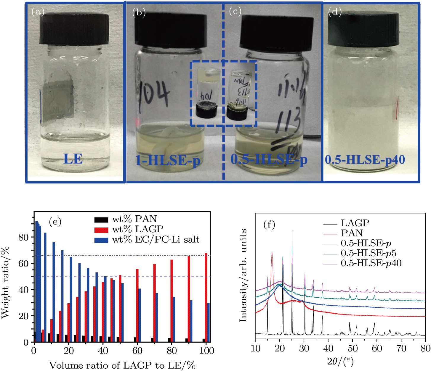
Recently, we proposed a new strategy of using a composite hybrid liquid/solid electrolyte (HLSE), which consists of a conventional organic liquid electrolyte (e.g., 1-M LiTFSI-EC/PC), widely adopted polymer (e.g., polyacrylonitrile, PAN), and a ceramic lithium ion conductor (e.g., Li1.5Al0.5Ge1.5(PO4)3, LAGP), prepared through a simple procedure. Liquid electrolyte (LE) in the electrolyte ensures high ionic conductivity and intimate contacts between electrolyte and electrodes. The polymer endows the electrolyte with a semi-solid state, extending the electrochemical window and flexibility. The ceramic lithium ion conductor in HLSE further extends the electrochemical window (up to about 4.8 V), which is suitable for most conventional cathodes including LiFePO4 and LiNixCoyMnzO2 (0 < x, y, z < 1, x + y + z = 1). The ceramic lithium ion conductor may provide extra ion transport pathways,[27] and reduce side reactions. Employing polymer and ceramic in the HLSE will reduce the LE content in the electrolyte/batteries, which will enhance the safety of batteries (see Fig. 1 and Figs. 2(a)2(e)). Thus, we can simply vary the ratio of the three base components to satisfy the requirements. Moreover, the preparation process is compatible with previous battery fabrication procedures and is easy to scale up. We were surprised to find that the concentration of lithium salt in the electrolytes fundamentally affects the properties of the electrolyte and the electrochemical performance.
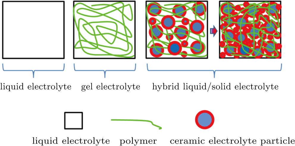
Fig. 1. (color online) Schematics of electrolyte evolution from liquid toward hybrid liquid/solid state.
Fig. 2. (color online) Optical photos of electrolytes: (a) liquid electrolyte; (b) and (c) hybrid liquid/solid electrolyte after polymer addition [(b) 1.0-HLSE-p and (c) 0.5-HLSE-p], the inserts are the photos after putting them upside down, and (d) 0.5-HLSE-p40, (e) weight percent variation of liquid electrolyte, PAN and LAGP in HLSE with different amounts of LAGP addition; (f) x-ray diffraction patterns of HLSEs and components used here.

Here, we report the novel properties of the HLSEs with excellent electrochemical performance by using a lower concentration of Li salt. The conductivity of the HLSE is over 2.25 × 10⁻³ S/cm at room temperature, comparable to that of a conventional liquid electrolyte. The HLSEs have extended electrochemical stable windows of up to 4.8 V versus Li/Li+. Li|HLSE|Li symmetric cells and Li|HLSE|LiFePO4 cells exhibit small interfacial area specific resistances (ASRs), which are comparable to that of LE, much smaller than that of ceramic LAGP electrolyte, and show very small polarization and stability at room temperature (RT).

2. Experiment

Ethylene carbonate (EC, anhydrous 99.0%, Aldrich) and propylene carbonate (PC, anhydrous 99.7%, Aldrich) were first mixed (1:1 vol.) to form the solvent. Then bis(trifluoromethane sulfonimide) (LiTFSI, dried at 80 °C under vacuum prior to use) was dissolved in the above solvent to obtain 0.5 M–2 M LiTFSI-EC/PC based liquid electrolyte (denoted as LE hereafter, water content < 20 ppm). Polyacrylonitrile (PAN, Mw ∼ 1.5 × 10⁵ purchased from Macklin, dried at 80 °C for 24 h under vacuum before use) and Li1.5Al0.5Ge1.5(PO4)3 (LAGP, purchased from Shenzhen MTI Corp.) were added to the base liquid electrolyte according to the required amount and vigorously stirred at 110 °C to form a homogeneous composite electrolyte. The obtained electrolytes were then coated onto the air laid paper consisting of 45% polyester and 55% cellulose fibers by simply immersing the air laid paper into the electrolyte, forming the composite separator after cooling down. All these processes were carried out in an argon filled glove box with H2O < 0.1 ppm and O2 < 0.5 ppm. There were two kinds of HLSE electrolytes. The first kind was prepared with only 8-wt% PAN addition to the base liquid electrolyte (LE), and the second one contained x-vol% LAGP (0 < x < 70) addition besides the 8-wt% PAN. They are abbreviated as y-HLSE-p and y-HLSE-px respectively for simplicity unless otherwise specified hereafter, where y indicates the concentration of LiTFSI, p indicates PAN and x denotes the volume ratio of LAGP to base LE, respectively.

The ionic conductivity of electrolytes was examined using a custom-made toolkit calibrated using standard potassium chloride (KCl) aqueous solution. The electrochemical window (Ewind) of the electrolyte was examined using the Li|Electrolyte|SS (stainless steel) configuration from 2.5 V to 5 V with a scan rate of 1 mV/s.

To prepare the LiFePO4 cathode, LiFePO4, carbon black and PVDF (80:10:10 by weight) were first mixed thoroughly using N-methyl pyrrolidone (NMP) solvent. Then the obtained slurry was spread evenly on aluminum foil to produce the green cathode film with active material loading of ∼ 5 mg/cm−2, the cathode films were then dried at 110 °C for 12 h under a vacuum prior to use.

The CR2032 coin cells were assembled in an argon filled glove box with lithium metal anode, LiFePO4 cathode, and the HLSE electrolyte. The charge/discharge cycling was performed on a LAND BT2000 battery tester.

3. Results and discussion

Figure 1 shows the design strategy for safer electrolytes of lithium ion batteries. The introduction of a polymer can immobilize the liquid electrolyte as the successful adopting of gel electrolytes in the battery industry, which effectively enhances the safety properties of batteries. Further addition of ceramic ionic conductor can again reduce the amount of liquid phase in the electrolyte, ensuring superior mechanical strength and safety performance. Figures 2(a)2(d) show the optical photos of various forms of electrolytes, from liquid to semi-solid, confirming the proposed strategy. With the introduction of polymer PAN, the composite electrolyte turns stiff and becomes the HLSE-p. Further addition of LAGP turns the HLSE-p electrolyte into HLSE-px. We can even obtain the free-standing electrolyte film by further increasing both PAN and LAGP content in the HLSE-px. Note that the 1.0-HLSE-p and 0.5-HLSE-p have different colors and viscosities, and their difference lies only in salt concentration (0.5 M versus 1 M) (see the inserts in Figs. 2(b) and 2(c)).

Figure 2(e) shows the weight ratios of LE, PAN, and LAGP in the composite HLSEs varying with the LAGP addition. The content of LE in HLSE decreases with the increase of LAGP. The LE content drops to 44.91 wt% when the volume of LAGP reaches 50% of LE and drops further to 29.7 wt% when the volume of introduced LAGP is the same as that of base LE. Figure 2(f) shows the x-ray diffraction (XRD) patterns of LAGP powder, PAN powder, and HLSEs. PAN powder is crystalline (red line), and becomes amorphous when organic LE (plasticizer) enters into the space between its chains (blue line). Feature peaks of LAGP appear when LAGP is added (black, green and pink lines).

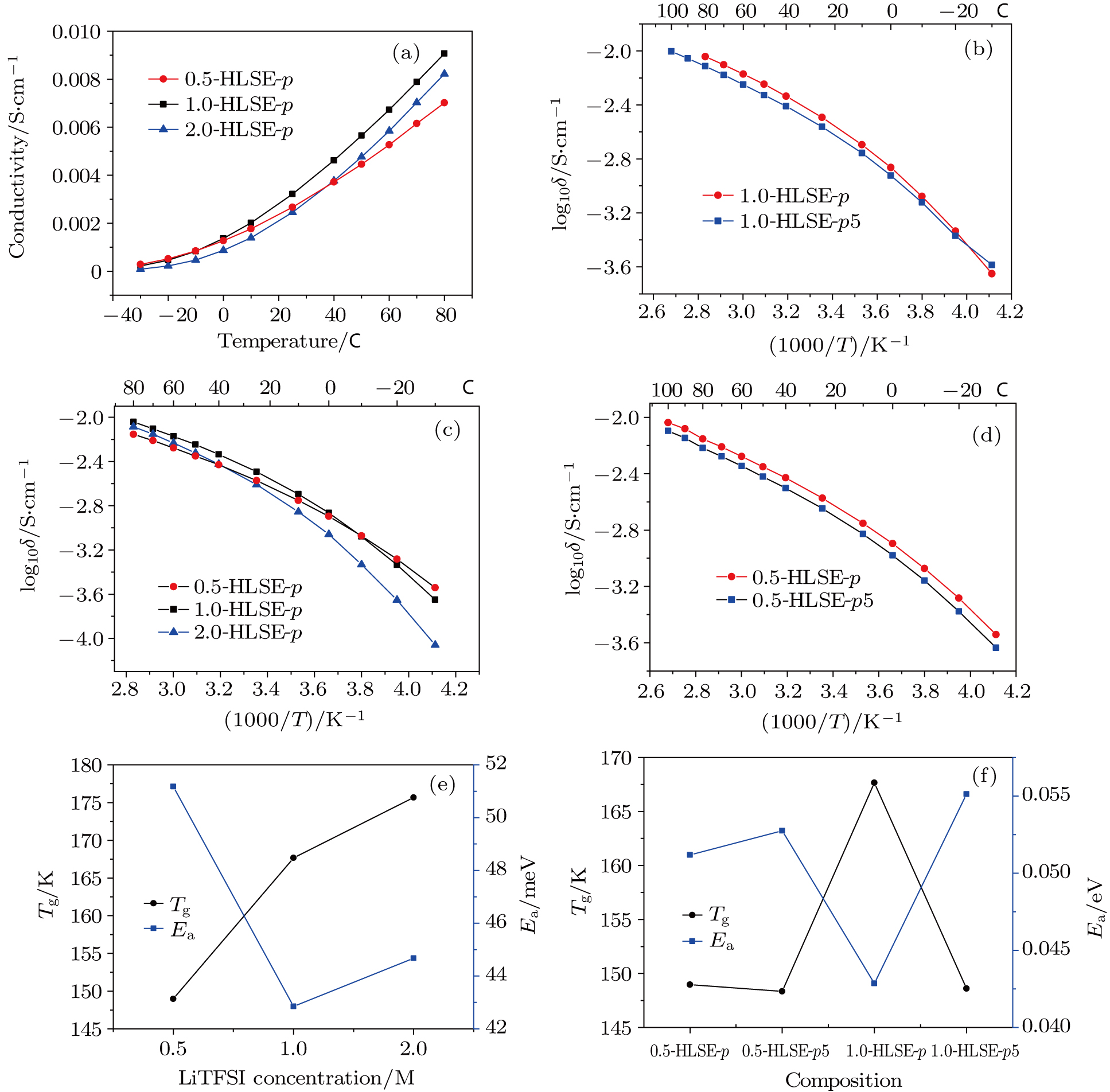
Figure 3(a) and Table 1 display the curves of temperature dependent ionic conductivity of HLSEs with 8-wt% PAN addition but different LiTFSI concentrations in the base liquid electrolyte in a temperature range of −30°C ∼ 80°C. The conductivity drops with the addition of PAN to the liquid electrolyte (Table 1). The electrolyte with 1 M LiTFSI (1.0-HLSE-p) has the highest conductivity among three electrolytes above 0 °C. The 0.5-HLSE-p has the lowest conductivity above 40 °C, while it is between 1.0-HLSE-p and 2.0-HLSE-p in a range of 0 °C ∼ 40°C, and higher than those in the other two (1-M and 2-M LiTFSI) in a low temperature range (−30°C ∼ 0°C). The 2.0-HLSE-p has the lowest ionic conductivity below 40°C (−30°C ∼ 40°C). The Li ionic conductivities decrease as temperature lowers for all the electrolytes. As for the conduction mechanism of Li ion in the electrolyte, there are the Arrhenius model and the Vogel–Tammann–Fulcher model or their combination. The bent curves in Figs. 3(a) and 3(c) suggest that the conductivities of those electrolytes follow the Vogel–Tammann–Fulcher equation (1):

where A is a constant, Tg and Ea are the glass transition temperature and ionic conducting activation energy respectively. The different curvatures of the curves indicate different Li+ ionic conduction mechanisms. Figure 3(e) shows the corresponding activation energy (Ea) of ionic conduction and glass transition temperature (Tg) deviated from fitting the data in Fig. 2(c) using the VTF model (equation (1)) versus LiTFSI salt concentration, respectively. The activation energy of 1.0-HLSE-p is lowest, while the other two have much higher values, which might originate from the insufficiency of lithium ion charge carriers for 0.5-HLSE-p and the formation of lithium ion pairs for 2.0-HLSE-p. On the other hand, the Tg values of all samples decrease with the increase of the LiTFSI salt concentration, and 0.5-HLSE-p corresponds to the lowest Tg of 148.9 K, favoring the transportation of lithium ions.

Fig. 3. (color online) (a) Ionic conductivities versus temperature for 0.5-,1.0-, and 2.0-HLSE-p, (b) log10δ/S versus 1000/T for 1.0-HLSE-p and 1.0-HLSE-p5, (c) log10δ/S versus 1000/T for 0.5-,1.0-, and 2.0-HLSE-p, (d) log10δ/S versus 1000/T for 0.5-HLSE-p and 0.5-HLSE-p5, (e) Tg and Ea values versus LiTFSI concentration, and (f) Tg and Ea values versus composition.

The ionic conductivity further drops when ceramic lithium ion conductor LAGP was introduced into 1.0-HLSE-p5 (Fig. 3(b) and Table 1) and 0.5-HLSE-p5 (Fig. 3(d) and Table 1). The conductivities also follow the trend of the VTF model and decrease with temperature. Again, the 0.5 M system (0.5-HLSE-p5) is different from the 1 M system (1.0-HLSE-p5) especially at the low temperature range. Figure 3(f) shows the composition dependent Tg and Ea values of the 0.5-M and 1-M systems in the cases with/without 5-vol% LAGP addition. The introduction of LAGP significantly reduces the Tg but increases the Ea for the 1-M system, while for the 0.5-M system, LAGP addition only slightly decreases the Tg and increases the Ea, suggesting a stronger interaction between LAGP ceramic and 1.0-HLSE-p than that between LAGP and 0.5-HLSE-p. The results confirm that the 0.5-M system favors Li ion transportation.

Table 1.

Ionic conductivities of HLSEs (in units mS/cm).

.

We further investigate their electrochemical behaviors as the 0.5-M system electrolyte shows different behavior from the others. The electrochemical stable window of the hybrid liquid/solid electrolyte extends to a higher potential with the addition of LAGP as shown in Fig. 4(a), possessing the value of about 4.8 V versus Li/Li+ with 40-vol% LAGP addition, suitable for most conventional cathodes including LiFePO4 and LiNixCoyMnzO2 (0 < x, y, z < 1, x + y + z = 1).
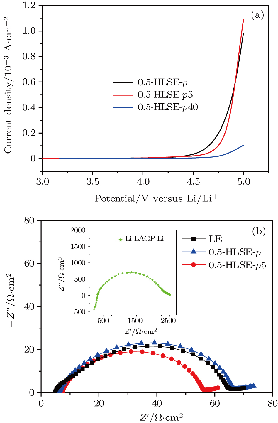
Fig. 4. (color online) (a) Plots of current density versus potential for the cases of 0.5-HLSE-p, -p5, and –p10, and (b) Nyquist plots of interfacial ASR between Li metal and electrolytes.

For the present reported solid-state batteries, the extremely large interfacial resistance limits their practical applications.[10] We evaluate the interfacial resistances between the metal Li anodes and the HLSEs using the symmetric cell. The ASRs are very close to that between the Li anodes and the liquid electrolyte as observed Fig. 4(b), while the ASR of Li-LAGP is two orders of magnitude larger, see the insert of Fig. 4(b).

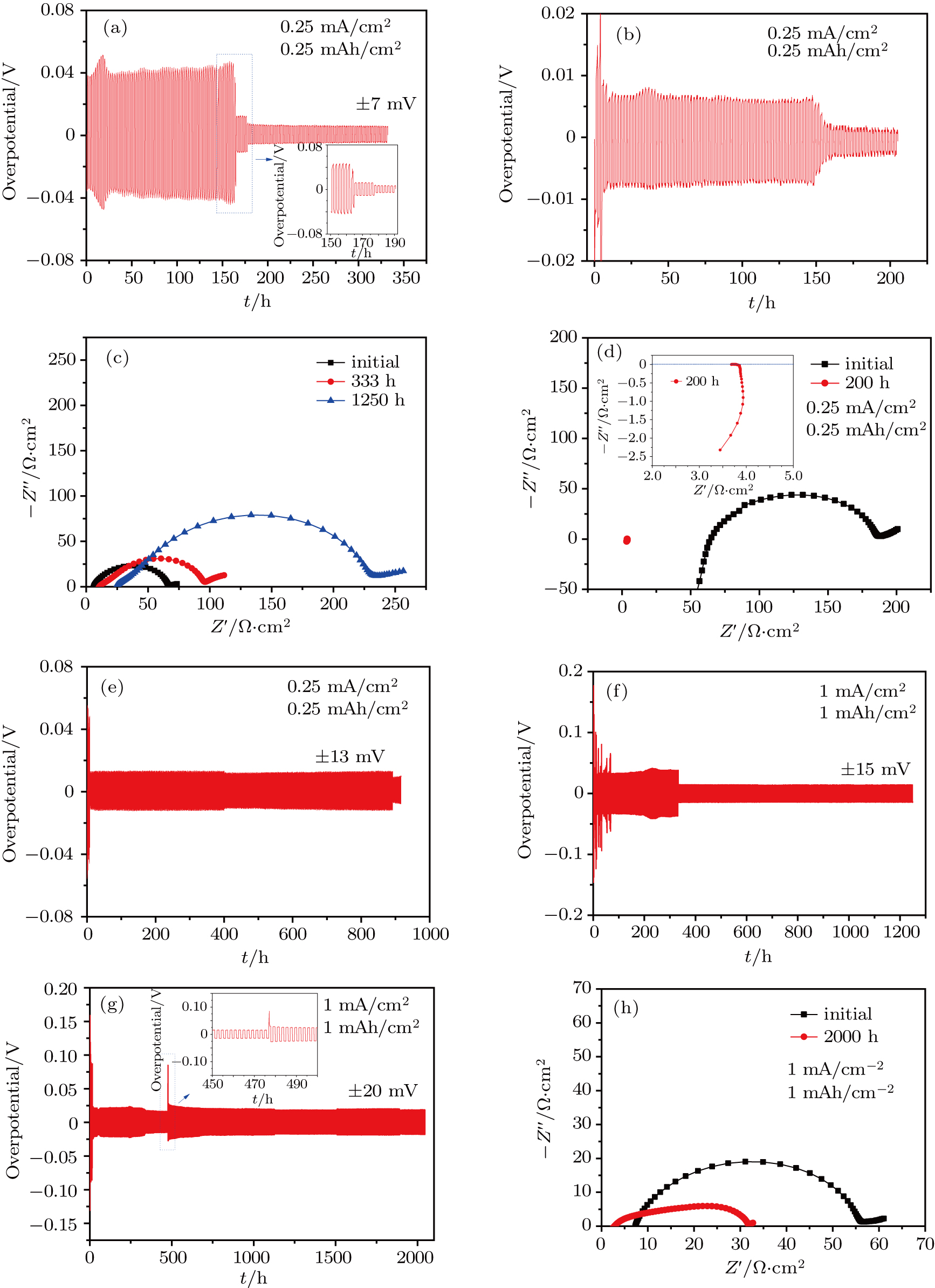
We also investigate the electrochemical behavior of the HLSE (0.5-HLSE-p5) using the Li symmetric cell with an electrolyte sandwiched between two metallic lithium. As shown in Fig. 5(a), the symmetric cell using 0.5-HLSE-p gives very small and smooth overpotential at the beginning and drops to a much smaller value of only 7 mV at a current density of 0.25 mA/cm2 and capacity of 0.25 mAh/cm2 in each half cycle. The sharp dropping of polarization in liquid electrolyte based symmetric cells is attributed to the internal short circuit by dendrite formation. This is also confirmed by our results in liquid electrolyte (see Figs. 5(b) and 5(d) and the insert),[28] while it is argued that the decrease in impedance for the case of 0.5-HLSE-p is not ascribed to the internal short circuit as indicated by the interfacial impedance shown in Fig. 5(c), which is different from that of liquid electrolyte and needs further investigation. In fact, the interfacial resistance gradually increases as the operation time increases, which originates from the side reactions (some for solid electrolyte interphase (SEI) formation) between 0.5-HLSE-p and metal lithium. When restarting the cycle test after the impedance measurement, the cell stably cycles for over 900 h still with very small polarization (only 13 mV) using the same current density and capacity as shown in Fig. 5(e). Three new overpotential droppings appear in the very first hours, around 400th and 870th hours. The symmetric cells are not shortened as confirmed again by the larger interfacial impedance after 1250 h in Fig. 5(c). As shown in Fig. 5(f), the symmetric cell runs smoothly with small polarization of 38 mV for about 330 hours and then drops to 15 mV, when the current density increases to 1 mA/cm2 and the capacity rises to 1 mAh/cm2. The larger interfacial resistance after running 1250 h in Fig. 5(c) further confirms the reaction between 0.5-HLSE-p (with only PAN addition) and metallic lithium. To alleviate the side reaction for the 0.5-HLSE-p, a lithium ion conductor LAGP is added into 0.5-HLSE-p to obtain 0.5-HLSE-px. The symmetric cell using 0.5-HLSE-p5 shows a very small overpotential of 25 mV and stably runs for over 2000 h at a current density of 1 mA/cm2 and capacity of 1 mAh/cm2 in each half cycle. The reduced ohmic resistance and ASR after 2000 h cycling suggest excellent interfacial contact between Li and 0.5-HLSE-p5 electrolyte, which is possibly because of the porous metallic lithium deposition on the anode surface.

Fig. 5. (color online) Polarizations of Li|electrolyte|Li symmetric cells with different current densities and capacities. [(a) and (e)] Li|0.5-HLSE-p|Li with 0.25 mA/cm2 and 0.25 mAh/cm2; (f) 1 mA/cm2 and 1 mAh/cm2; (b) Li|LE|Li with 0.25 mA/cm2 and 0.25mAh/cm2; (g) Li|0.5-HLSE-px|Li with 1 mA/cm2 and 1 mAh/cm2; the Nyquist plots of (c) Li|0.5-HLSE-p|Li before cycling (black solid square), after 333 h (red solid cycle) and 1250 h (blue solid triangle) cycling, with 0.25 mA/cm2, 0.25 mAh/cm2; (d) Li|LE|Li before cycling (black solid square), after 200 h (red solid cycle), with 0.25 mA/cm2, 0.25 mAh/cm2; of (g) Li|0.5-HLSE-px|Li before (black solid square) and after 2000 h (red solid cycle) cycling, with 1 mA/cm2, 1 mAh/cm2.

Figure 6 displays the SEM images of the Li anode surface of Li|0.5-HLSE-p|Li and Li|0.5-HLSE-p5|Li symmetric cells after cycling for 1250 h and 2000 h at a current density of 1 mA/cm2 and capacity of 1 mAh/cm2 in each half cycle. Figure 6(a) shows the porous SEI formed on the surface, confirming the gradual growth of ASR, while the addition of LAGP is beneficial to the formation of dense smooth SEI and thus ensuring the intimate contact of the electrode-electrolyte interface. The thick dense layer further prevents possible side reactions between Li and HLSEs.

Fig. 6. SEM images of surface Li anode of (a) Li|0.5-HLSE-p|Li after 1250 h, and (b) Li|0.5-HLSE-p5| after 2000-h cycling at 1 mA/cm2 with a capacity of 1 mAh/cm2 in each half cycle.

When adopted in the Li–LiFePO4 cell, the HLSEs exhibit unexpectedly small impedance compared with that in the 1-M LiTFSI EC/PC liquid electrolyte as shown in Fig. 7(a). Due to non-ideal SEI formation, the 0.5-HLSE-p electrolyte reacts with metallic Li occasionally during cycling, leading to low Coulombic efficiency. The addition of LAGP will contribute to the SEI formation besides the possible mechanical merits.[29] The initial Coulombic efficiency is only 49% due to the formation of SEI, and the Coulombic efficiencies increase to 92.1% and 99.2% for the second and third cycle in Figs. 7(b) and 7(d), confirming the good construction of SEI. The cell also displays excellent rate performance as presented in Fig. 7(c). Reversible capacities are 146.3 mAh/g at 0.1 C and 128 mAh/g at 1 C. The capacity retentions are 97.5%, 95.5%, and 90.5% after 100, 200, and 300 cycles, respectively.

Fig. 7. (color online) (a) Nyquist plots of Li|HLSE|LiFePO4 cells, (b) the 1st to 5th charge/discharge curves, (c) curves of rate performance, and (d) plots of cycle performance of Li|0.5HLSE-p5|LiFePO4 cell.

It is worthwhile pointing out that for 1.0-HLSEs, robust SEI can be formed rapidly and effectively suppress side reactions only when a much greater amount of LAGP (40 vol%) is introduced (which will soon be published in our next work), which again verifies the importance of lithium salt concentration in HLSEs.

4. Conclusion and perspectives

In this work, we report novel hybrid liquid/solid electrolytes (HLSEs) with excellent electrochemical performance by simply using a lower lithium salt concentration. The HLSEs show conductivities of over 2.25 × 10⁻³ S/cm at RT, comparable to that of a conventional liquid electrolyte, and extend electrochemical stable windows of up to 4.8 V versus Li/Li+. The lower LiTFSI concentration favors the suppression of the side reaction in HLSE. The Li|HLSE|Li symmetric cells and Li|HLSE|LiFePO4 cells exhibit small interfacial ASRs comparable to that of the liquid electrolyte while much smaller than that of the ceramic LAGP electrolyte, thus showing very small polarization, excellent rate and cyclic performance at room temperature.

The molecular mechanism of how the lithium salt affects the properties of the HLSEs needs further investigation. We can also change the content/composition of polymer and ceramic electrolyte to further reduce the LE content in the system, thus improving safety, which is useful in practical applications.

Reference
[1] Taracson J Armand M 2001 Nature 414 359
[2] Zu C X Li H 2011 Energy Environ. Sci. 4 2614
[3] Xu W Wang J Ding F Chen X Nasybulin E Zhang Y Zhang J G 2014 Energy Environ. Sci. 7 513
[4] Cheng X B Zhang R Zhao C Z Zhang Q 2017 Chem. Rev. 117 10403
[5] Inaguma Y Chen L Q Itoh M Nakamura T Uchida T Ikuta H Wakihara M 1993 Solid State Commun. 86 689
[6] Xu X Wen Z Yang X Zhang J Gu Z 2006 Solid State Ionics 177 2611
[7] Murugan R Thangadurai V Weppner W 2007 Angew. Chem. Inter. Ed. 46 7778
[8] Xu X Wen Z Wu X Yang X Gu Z 2007 J. Am. Ceram. Soc. 90 2802
[9] Manthiram A Yu X Wang S 2017 Nat. Rev. Mater. 2 16103
[10] Sharafi A Meyer H M Nanda J Wolfenstine J Sakamoto J 2016 J. Power Sources 302 135
[11] Kerman K Luntz A Viswanathan V Chiang Y M Chen Z 2017 J. Electrochem. Soc. 164 A1731
[12] Zhou D He Y B Cai Q Qin X Li B Du H Yang Q H Kang F 2014 J. Mater. Chem. A 2 20059
[13] Zhou D He Y B Liu R Liu M Du H Li B Cai Q Yang Q H Kang F 2015 Adv. Energy Mater. 5 15
[14] Yao X Liu D Wang C Long P Peng G Hu Y S Li H Chen L Xu X 2016 Nano Lett. 16 7148
[15] Zhou D Liu R He Y B Li F Liu M Li B Yang Q H Cai Q Kang F 2016 Adv. Energy Mater. 6 7
[16] Zhou W Wang S Li Y Xin S Manthiram A Goodenough J B 2016 J. Am. Chem. Soc. 138 9385
[17] Han X Gong Y Fu K K He X Hitz G T Dai J Pearse A Liu B Wang H Rubloff G 2017 Nat. Mater. 16 572
[18] Liu K Pei A Lee H R Kong B Liu N Lin D Liu Y Liu C Hsu P C Bao Z Cui Y 2017 J. Am. Chem. Soc. 139 4815
[19] Pan Q Barbash D Smith D M Qi H Gleeson S E Li C Y 2017 Adv. Energy Mater. 7 1701231
[20] Yang L Wang Z Feng Y Tan R Zuo Y Gao R Zhao Y Han L Wang Z Pan F 2017 Adv. Energy Mater. 7 1701437
[21] Bhattacharyya A J Maier J 2004 Adv. Mater. 16 811
[22] Pfaffenhuber C Göbel M Popovic J Maier J 2013 Phys. Chem. Chem. Phys. 15 18318
[23] Veith G M Armstrong B L Wang H Kalnaus S Tenhaeff W E Patterson M L 2017 ACS Energy Lett. 2 2084
[24] Tan R Gao R Zhao Y Zhang M Xu J Yang J Pan F 2016 ACS Appl. Mater. Interfaces 8 31273
[25] Park M S Jung Y C Kim D W 2018 Solid State Ionics 315 65
[26] Stephan A M 2006 European Polymer J. 42 21
[27] Zheng J Tang M Hu Y Y 2016 Angew. Chem. Inter. Ed. 128 12726
[28] Wu B Lochala J Taverne T Xiao J 2017 Nano Energy 40 34
[29] Wu J Y Ling S G Yang Q Li H Xu X X Chen L Q 2016 Chin. Phys. B 25 078204