1. IntroductionLorentz transmission electron microscopy (TEM) has been extensively used to study magnetic domain structures formed due to the interactions between the electron beam and the emergent magnetic fields accompanying their intrinsic local magnetization distribution. It provides detailed insight into magnetic structures as well as compositional and electronic structures with high spatial resolution of 0.1 nm–1.0 nm for structural imaging, 1 nm–3 nm for extraction of compositional information, and 2 nm–20 nm for magnetic imaging.[1–3] The observation of magnetic domains and the corresponding evolution behavior under external fields provides direct link to the macroscopic physical properties and applications.
Formation of magnetic domains is due to the competition among the magnetic energies, such as magneto-anisotropic, ferromagnetic exchange, and magnetostatic energies. The energetically preferred magnetic domains are generated to minimize the total energy.[1,4–7] In recent times, nanoscale topological magnetic configurations have received enormous attention from the viewpoint of both fundamental science and potential application in next generation of spintronic devices with high-density and low-power consumption. Magnetic vortices,[8–10] skyrmions,[6,11,12] and nanometric bubbles[13–15] are typically such topological magnetic configurations. For such magnetic domains with nanometer size, Lorentz TEM with its high spatial magnetic resolution has made significant success in characterizing the detailed spin configurations and the response of those topological magnetic domains to the external magnetic fields,[16,17] temperatures,[18,19] and electric currents,[12,20–22] etc., thus leading to an immense exploration of new materials and potential applications in new spintronic devices.
We give a general introduction of the Lorentz TEM and its application in characterizing the topological spin configurations. In Section 2, we briefly describe the principle of Lorentz TEM and the microscopic techniques for imaging magnetic domains. The spin configuration and the dynamic behavior under external fields of the topological magnetic domains such as magnetic vortices, skyrmions, and bubbles via in situ Lorentz TEM are discussed in Section 3, which is followed by a general conclusion and outlook for the Lorentz TEM study on topological magnetic domains in Section 4.
2. Lorentz TEM: principle and imaging methodsA TEM specimen is characterized under the normal operation mode by using a high-current objective lens (OL) for minimizing the focal length to achieve higher magnification and better spatial resolution. In this case, a strong magnetic field of around 2 T–3 T is applied to the specimen. Such a strong magnetic field saturates the magnetic material, leaving no magnetic domain wall contrast. The intrinsic magnetic domains should be identified under the controllable external fields to provide the real magnetic structure information. In the Lorentz mode, however, we observe the magnetic domains by turning the OL off and manually increasing the magnetic fields continuously by adjusting the OL current in so-called “free lens-control mode” or by using the specially designed JEOL dedicated Lorentz TEM where the residual magnetic field is ignorable at around 4 Oe to 10 Oe (1 Oe = 79.5775 A⋅m−1).[1,23] It should be mentioned that the OL should be switched off during the magnetic sample insertion even for the dedicated Lorentz TEM since the sample is subjected to about 350 Oe field during insertion, which will change the original magnetic domain structures, especially for the soft magnetic materials.[23]
The principle of magnetic domain images obtained from Lorentz TEM or Lorenz mode of standard TEM is based on the electron beam passing through the magnetic material, where the in-plane magnetization induces a Lorentz force normal to both the magnetization and the perpendicular electron beam. The electron beam is deflected by Lorentz force, FL, as a result of the presence of an electrostatic field E and/or a magnetic field B within and around the sample:
In Lorentz TEM, only the in-plane components of the magnetic induction
Bxy contribute to the deflection angle, which is typically much smaller than the Bragg angle of a few milliradians.
[24–26] The out-of-plane magnetic components cannot affect the electron propagation, and thus the out-of-plane magnetic components cannot be detected. These deflected electrons are finally converged or diverged near the domain walls with the domain contrast imaged in the imaging plane.
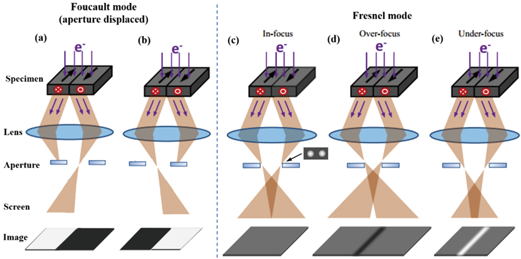
2.1. Fresnel and Foucault methodsThe most common techniques for imaging the magnetic domains in TEM are Foucault and Fresnel modes, and their corresponding schematics are shown in Fig. 1.[27] For the purpose of illustration, a simple specimen comprising oppositely magnetized 180 °C domains is assumed. When the parallel electron beam passes through the magnetic domain region, the Lorentz force leads to the deflection of the electrons and the diffraction spot splits into two by following the right-hand rule as shown schematically in Fig. 1(c). One split spot contains information about domains with magnetic moments lying in one direction, and the other spot contains information about the antiparallel domains.[24,27,28]
In the Foucault mode as shown in Figs. 1(a)–1(b), one of the split spots due to the deflection of the electrons in the diffraction pattern is selected by an objective aperture in the focal plane to image the magnetic domains while keeping the imaging lens in-focus. The domains with antiparallel magnetization show bright and dark contrast depending on which split spot is selected. The magnetization direction in the domains can be identified if the relative direction of aperture displacement with respect to the image is known. To obtain high-quality Foucault-mode images, the back-focal plane of the objective lens and the blocking aperture must be as near coplanar as possible. It is inconvenient to carry out dynamic imaging of magnetization in Foucault mode under external fields since both the electron beam and the aperture position relatively shift and the split spots change with external fields.
For imaging the magnetic domains in Fresnel mode as shown in Figs. 1(c)–(e), the deflecting electrons are focused in the final image plane and no magnetic contrast appears in the in-focus conditions. However, when the Lorentz TEM is in the over-focused condition, the electron deflection induces a decreased intensity contrast because the electrons are deflected away from the domain wall. This results in the appearance of dark contrast lines in the domain wall regions. Similarly, bright contrast lines appear in under-focused conditions due to the increased electron density caused by the converged electrons. In this sense, the inversion of the magnetic contrast at the domain walls is observed between the over- and under-focused images. This is the classic Fresnel imaging mode. Different from the Foucault mode, the bright and black contrasts indicate the domain wall position, not the magnetization from inner magnetic domains. It should be noted that the spatial resolution of Fresnel mode is not as high as that of Foucault mode because the images must be recorded at a relatively large objective lens defocus in order to manifest the contrast of domain walls. The advantages of Fresnel imaging mode are its ease of operation and significant contrast. It is also convenient for performing real-space in situ observation, allowing recording of dynamic domain evolution behavior during magnetizing and manipulation under external fields.[29]
In order to quantitatively determine the direction of magnetization and the spin configuration of magnetic domains using Lorentz TEM images, a method named transport-of-intensity equation (TIE) is generally adopted based on Fresnel mode, which is briefly introduced as follows. When a plane wave of electrons passes through a TEM specimen, the direction of transmitted electrons varies owing to the Lorentz force caused by the interaction between electron wave and specimen, and hence the different image intensity is produced. The image intensity includes both the amplitude and phase information of the transmitted electron wave. TIE can be used to detect the phase information from the intensity distribution as follows:[30]
where
I(
x,
y,
z) and
ϕ(
x,
y,
z) are the intensity and phase distributions of the transmitted electron wave, respectively. The phase shift of electron wave corresponds to the integration of electrical potential and magnetic vector potential along the propagating path, which is contributed by the specimen. ∇
xyϕ(
x,
y,
z) is the differentiation of the phase of an electron beam in a specimen plane, which represents the sum of electrical and magnetic potential of the specimen. The electrical potential corresponds to the inner potential of the specimen which is related to the specimen composition and thickness. In the case of homogenous composition and thickness, a uniform electrical potential is simply superimposed on the magnetic potential and hence does not affect the evaluation of the magnetic information. From the Maxwell-Ampere equation, the electronic phase
ϕ(
x,
y,
z) and magnetization (
M) satisfy the following relationship:
where
t and
nz are the sample thickness and the unit vector along the normal direction of the material surface, respectively. Therefore, if the
ϕ(
x,
y,
z) is known, the in-plane magnetization
M can be obtained using Eq. (
3), and then if
∂I(
x,
y,
z)/
∂z is known,
ϕ(
x,
y,
z) can be given by Eq. (
2), and
∂I(
x,
y,
z)/
∂z can be obtained from the Lorentz TEM experimental data. The magnetization distribution in the specimen plane can be obtained by differentiating the phase distribution of an electron beam with respect to
z.
∂I(
x,
y,
z)/
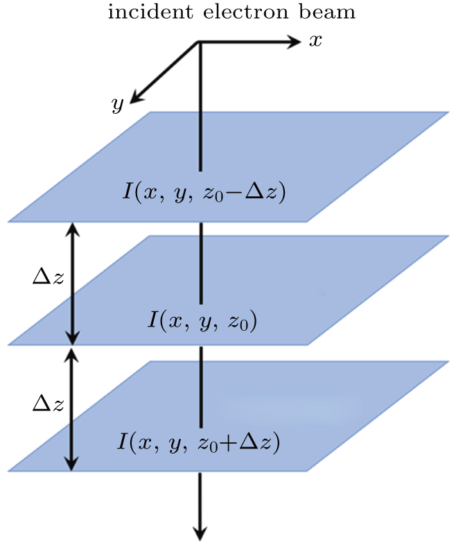
∂z can be approximately expressed as:
where
z0 is the focus distance of the objective lens and 2Δ
z is the distance between the over-focus and under-focus planes with 2Δ
z ≪
z0, as schematically shown in Fig.
2.
I(
x,
y,
z0 − Δz),
I(
x,
y,
z0), and
I(
x,
y,
z0 + Δz) are intensity distributions of Lorentz images at under-focus, just-focus and over-focus conditions, respectively.
Therefore, the lateral magnetization distribution can be quantified using the above TIE method to analyze the electron intensity differences of Lorentz TEM images with different focus values. This knowledge has been developed into a commercial QPt software embedded in widely used Digital Micrograph (DM) TEM interface.
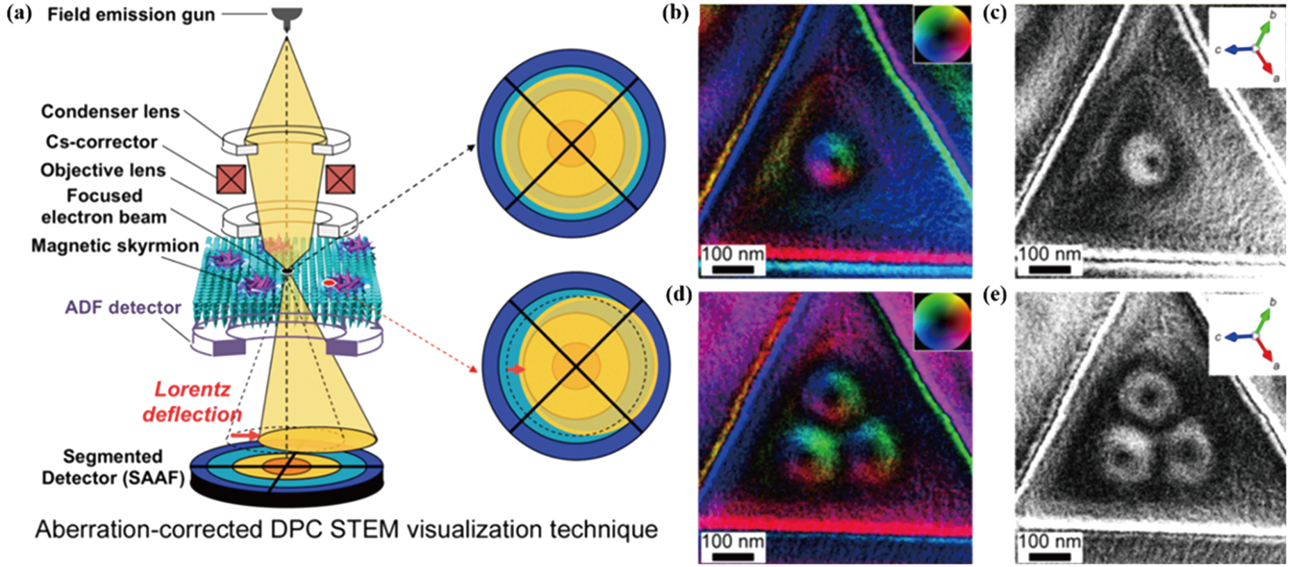
2.2. Differential phase contrast (DPC) imaging techniqueDifferential phase contrast (DPC) in Lorentz TEM is a high-resolution magnetic imaging technique for visualizing electromagnetic field distribution via measuring the deflection of an electron beam at each beam-scan point.[28,31,32] The differential phase contrast (DPC) technique, principally described in Fig. 3(a), requires a field emission gun source to create a very high monochromatic electron beam with converged probe scanning across the specimen similar to the normal scanning transmission electron microscopy (STEM).[33] When the electron beam scans through the specimen, a cone of illumination beam carrying the differential or gradient of the electron wave phase is projected onto a circular quadrant detector. If the specimen is non-magnetic, the disc will be centered on the detector. If the specimen is magnetic, the Lorentz force deflects the electrons and shifts the disc to a position that is no longer concentric on the detector. Each segment of the detector measures a separate electron signal. The different signals taken from opposite segments of quadrants provide the magnetic induction information as two orthogonal components. The resolution in DPC Lorentz TEM depends on the probe size and the best resolution commonly achieved is in the range of 2 nm–5 nm.[34,35] In recent past, for aberration-corrected STEM, the best resolution of about 0.9 nm in DPC Lorentz STEM was reported.[31] High resolution, straightforward interpretation, and easy mapping of magnetic induction are the main advantages of DPC. For example, the DPC STEM images demonstrate the spin configuration of the transition from a single-skyrmion state (Figs. 3(b)–3(c)) to a triple-skyrmion state (Figs. 3(d)–3(e)) in a very narrow range of perpendicular magnetic fields at 295 K in Co8Zn8Mn4.[33]
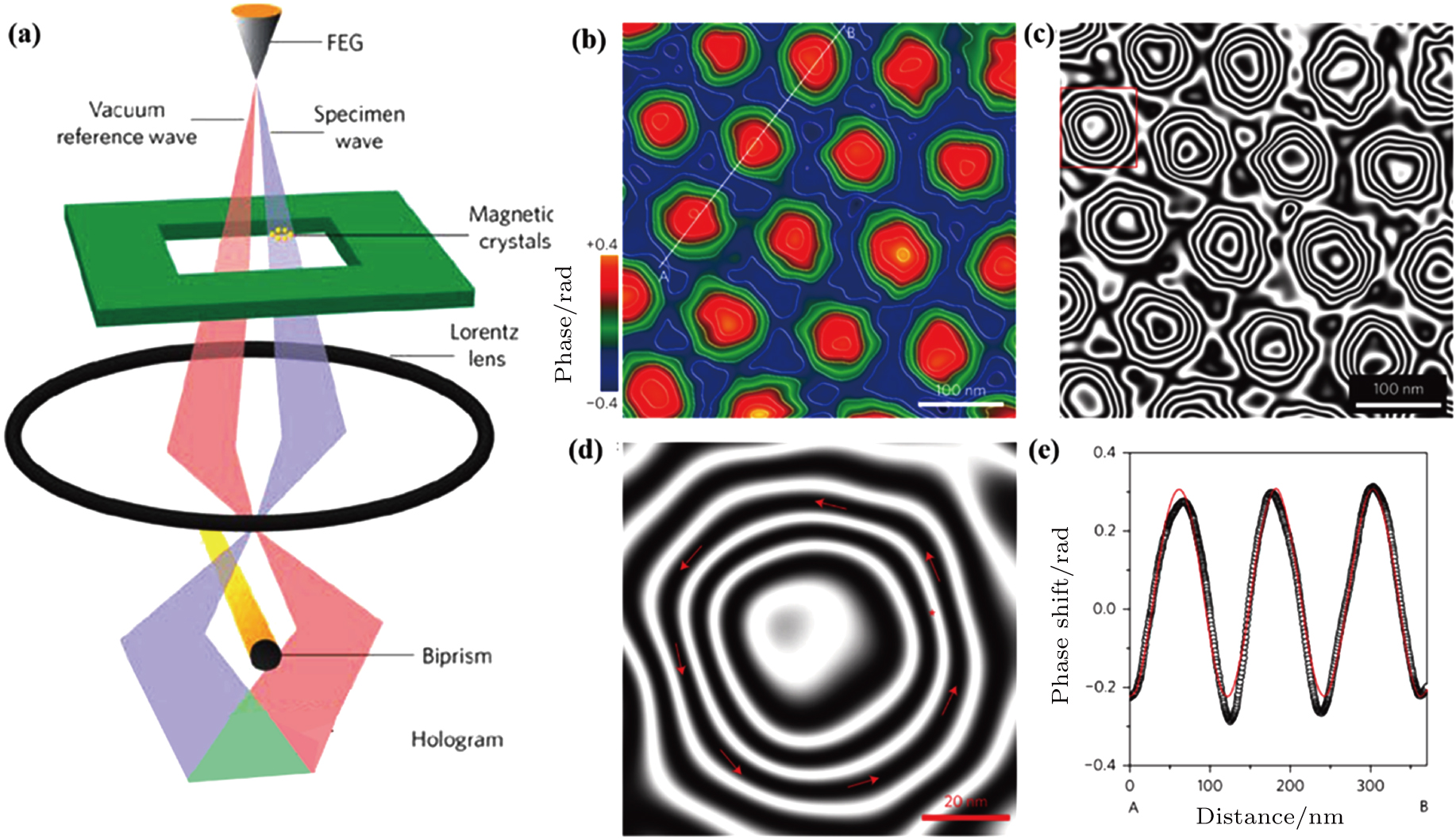
2.3. Off-axis electron holographyAnother magnetic imaging technique in Lorentz TEM is off-axis electron holography, which is based on the interference of electron waves passing through the sample (object wave) and the vacuum (reference wave), as shown schematically in Fig. 4(a).[36–38] The critical requirement for electron holography is a coherent source of electrons together with a thin and uniform TEM specimen. When the electron wave passes through the sample, the phase shift in the exit wave contains the sample information of both magnetic and electric potentials. An electron biprism inserted between the back focal plane and the image plane superimposes the exit wave and the reference wave resulting in an interference pattern (hologram) in the image plane. From the hologram, the electron wave can be reconstructed in the form of two images, an amplitude image and a phase image. The measured phase shift can be expressed in the form:[39–41]
where
z is the incident electron beam direction,
x is the sample’s in-plane direction,
CE is a constant that depends on the accelerating voltage of a microscope,
V is the electrostatic potential, and
B is the in-plane component of the magnetic induction. If neither
V nor
B varies along the incident electron beam direction, further removal of the electrostatic contribution and differentiation results in the phase gradient expression, which is directly proportional to the in-plane component of the magnetic induction:
where
t is the sample thickness. Depending on the quality of the phase reconstruction algorithm, electron holography can image the magnetic structure with high resolution up to 1 nm–2 nm. However, it should be noticed that electron holography requires an algorithm, commonly based on Fourier transformation to recover the phase information from the hologram. Besides, the field view in electron holography seems to be limited since some vacuum region should be included, which may introduce the stray fields near the edge.
[42–44] Figures
4(b)–
4(c) illustrate the use of electron holography to image the magnetic flux maps of the skyrmion lattices in Fe
1−xCo
xSi thin film.
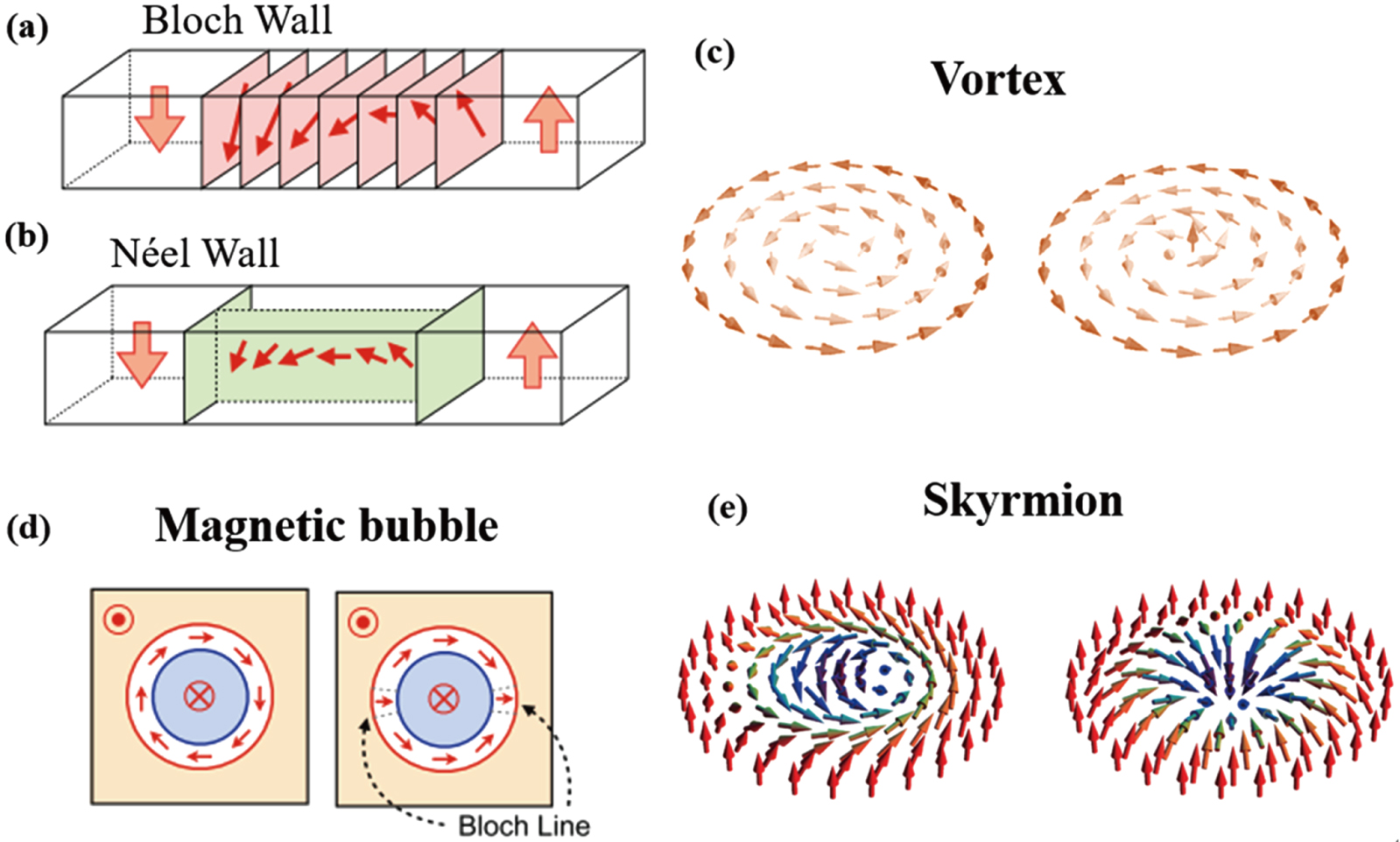
[37] 3. Topological magnetic domainsThe competing magnetic interactions can generate different types of magnetic domains. At the magnetic domain boundary, the magnetic moment continuously transits from one magnetization direction to another, resulting in magnetic domain walls. The typical domain walls are Bloch-type and Néel-type. In the Bloch wall, the magnetic moments gradually rotate in a plane parallel to the wall, whereas in the Néel wall, the magnetic moments rotate in a plane normal to the wall, as shown in Figs. 5(a)–5(b). In recent past, topology concept from mathematics has been developed to describe the properties of topological spaces that are invariant under a continuous transformation.[45] In condensed matter physics, the topological phase has been found to be closely related to numerous physical phenomena such as Aharonov–Bohm effects,[46] Berry phase,[47] Josephson effect,[48] quantum Hall effects,[49–53] bubbles,[54] and skyrmions[55] schematically described in Figs. 5(c)–5(e), have aroused tremendous attention due to their promising applications such as information storage, transportation and processing in spintronic devices. The swirling configuration of topological domains can be characterized by the topological number defined as
 | |
where
M(
x,
y) represents the spatially varying in-plane
magnetization and
It was used to count the number of times
n(
r) =
n(
x,
y) wraps the unit three-dimensional (3D) sphere in the order-parameter space. And this topological invariant cannot be changed by a continuous deformation. The magnetization gradually rotates with two degrees of freedom, which are helicity and vorticity. The helicity is the rotational direction of the in-plane magnetizations along the perimeter (i.e. clockwise (CW) or counterclockwise (CCW)), and the vorticity determines the topological number as
N =
m, which is defined by the integer
.
[6]The nanometric domains with topological properties have demonstrated strong anti-interference ability and the easily-manipulable behavior, which may lead to their application in magnetic storage and spintronic devices. Uniaxial magnetic anisotropy is an important parameter that determines the topological spin configuration. Magnetic vortex exists especially in submicron disk-shaped nanodots with low uniaxial anisotropy, owing to the edge constriction and the competition between exchange and magnetic dipole–dipole interaction.[56,57] The “in-plane” and “out-of-plane” vortices are schematically shown in Fig. 5(c). For an “out-of-plane” vortex, the spins cover only half of the 3D unit sphere surface and thus the topological number is calculated to be ± 1/2.[53,58] In recent times, magnetic skyrmions, particle-like swirling spin structures characterized by a quantized topological number, have attracted considerable research attention owing to their peculiar dynamic response to external fields and highly promising properties in spintronic device applications. A magnetic skyrmion comprises magnetic moments pointing in all directions wrapping a sphere. Magnetic moments are parallel to an applied magnetic field at its periphery but antiparallel at its center for both Bloch and Néel-type skyrmion in a two-dimensional (2D) plane, as shown in Fig. 5(e).[55] The number of such wrappings corresponds to a topological invariant, which is an integer, and thus the skyrmion has topologically protected stability. Magnetic bubbles are regarded as rod-like domains with antiparallel magnetic moments separated via a cylindrical Bloch wall, preferring to exist in magnetic films with higher perpendicular anisotropy. The different magnetic moment distribution at the domain wall separates the magnetic bubbles with two different topological number of 1 and 0 as shown in Fig. 5(d). The magnetic moments in the domain wall continuously rotate around the disk center for the bubbles with topological number 1, while a pair of vertical Bloch lines (BLs) exists at the domain wall for the bubbles with topological number 0.[54,59]
In parallel with high-resolution Lorentz TEM imaging, in situ manipulation of these topological domains under different external stimulations helps correlate the phase transition and magnetic structures with magnetic properties, prompting these topological magnetic domains into practical applications. Next, we will successively review the generation and manipulation of magnetic vortex, skyrmions, and bubbles, which have been recently studied via Lorentz TEM in the magnetic materials with different anisotropy.
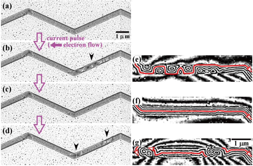
3.1. The generation and manipulation of magnetic vortex in permalloy nanowire and amorphous CeFeBMagnetic vortex has been studied mostly in permalloy with the pattern constriction to exemplify its potential applications in magnetic random access memory.[56,57,60] Lorentz TEM observation gives direct and clear images about the topological magnetic vortices and particularly their dynamic behavior in correlation to the application. Figure 6 demonstrates the current-excited magnetization dynamics in a permalloy nanowire by in situ Lorentz TEM and the quantitative distribution of magnetic flux lines by electron holography. The pulsed electric current of 2.0 × 10¹¹ A/m2 with 300-ns interval was applied to the uniformly magnetized state of the nanowire from right to left at zero magnetic field as shown in Fig. 6(a). Chained vortices and crosstie walls nucleated from the uniformly magnetized state due to the stimulation of the electric current pulse as shown in Fig. 6(b) and Fig. 6(e). Such nucleated vortices annihilated immediately before the next current pulse arrived and turned into a uniformly magnetized state in probability as high as 90% (Fig. 6(d) and Fig. 6(c)). Interestingly, paired domain walls nucleated from the uniformly magnetized domain state as shown in Fig. 6(d).[57]
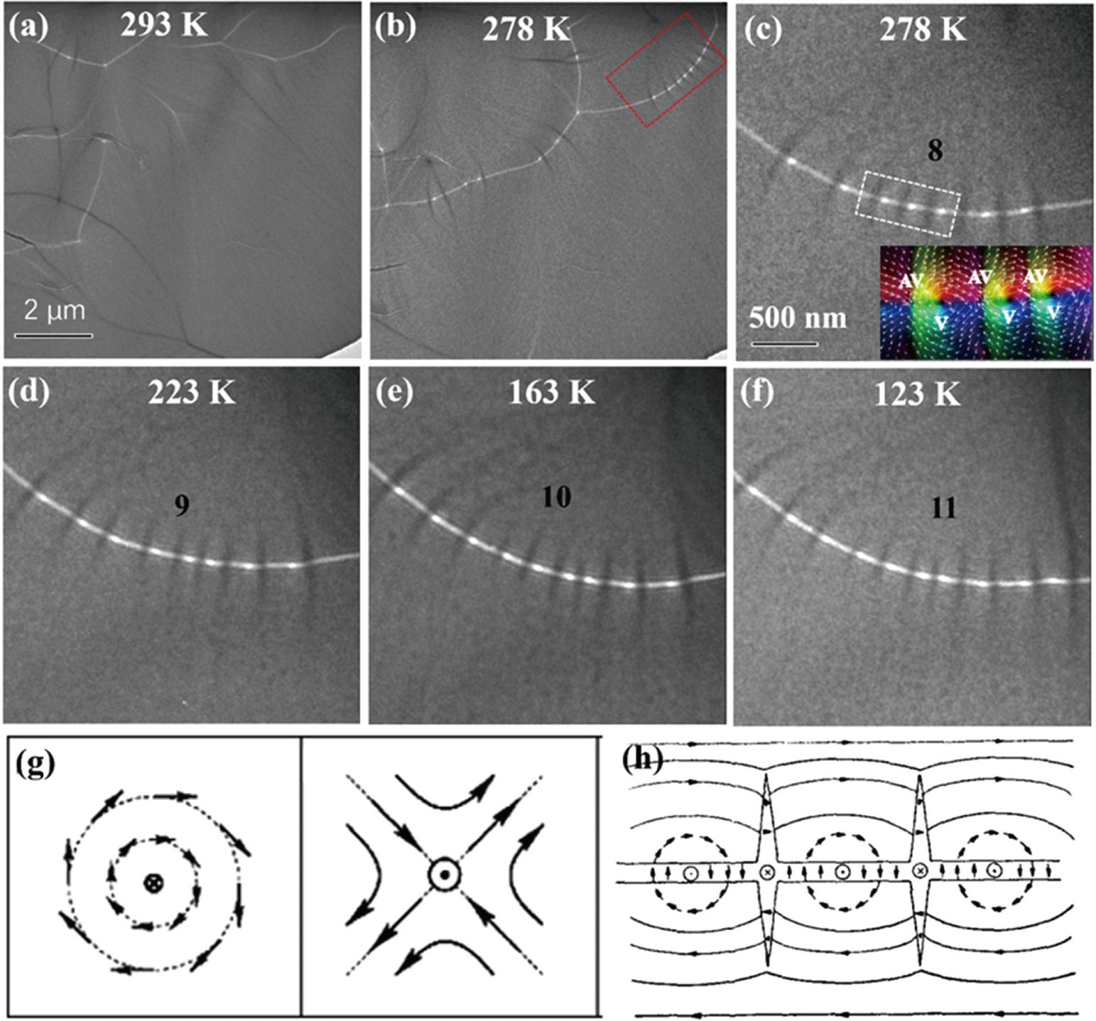
Besides the typical vortex study in patterned permalloy, amorphous Ce14Fe80B6 ribbon has been recently explored to demonstrate the generation and manipulation of magnetic vortices without pattern constriction.[61] Figure 7 shows the temperature dependence of vortex–antivortex (V–AV) evolution. Figure 7(b) shows more V/AV in the chains of cross-tie domain walls (DWs) at lower temperatures of 278 K than at 293 K (Fig. 7(b)). Figures 7(c)–7(f) demonstrate the temperature dependence of the magnetic textures in the red-selected region without obvious defects (Fig. 7(b)). Upon cooling from 293 K to 123 K, the number of magnetic vortices is increased because of the pairwise nucleation of vortices and anti-vortices. The inset of Fig. 7(c) shows the in-plane magnetic configuration of the cross-tie wall, reconstructed by TIE analysis, similar to the spin configuration of the schematic vortex and antivortex along the cross-tie domain wall as shown in Figs. 7(g)–7(h).[10,62]
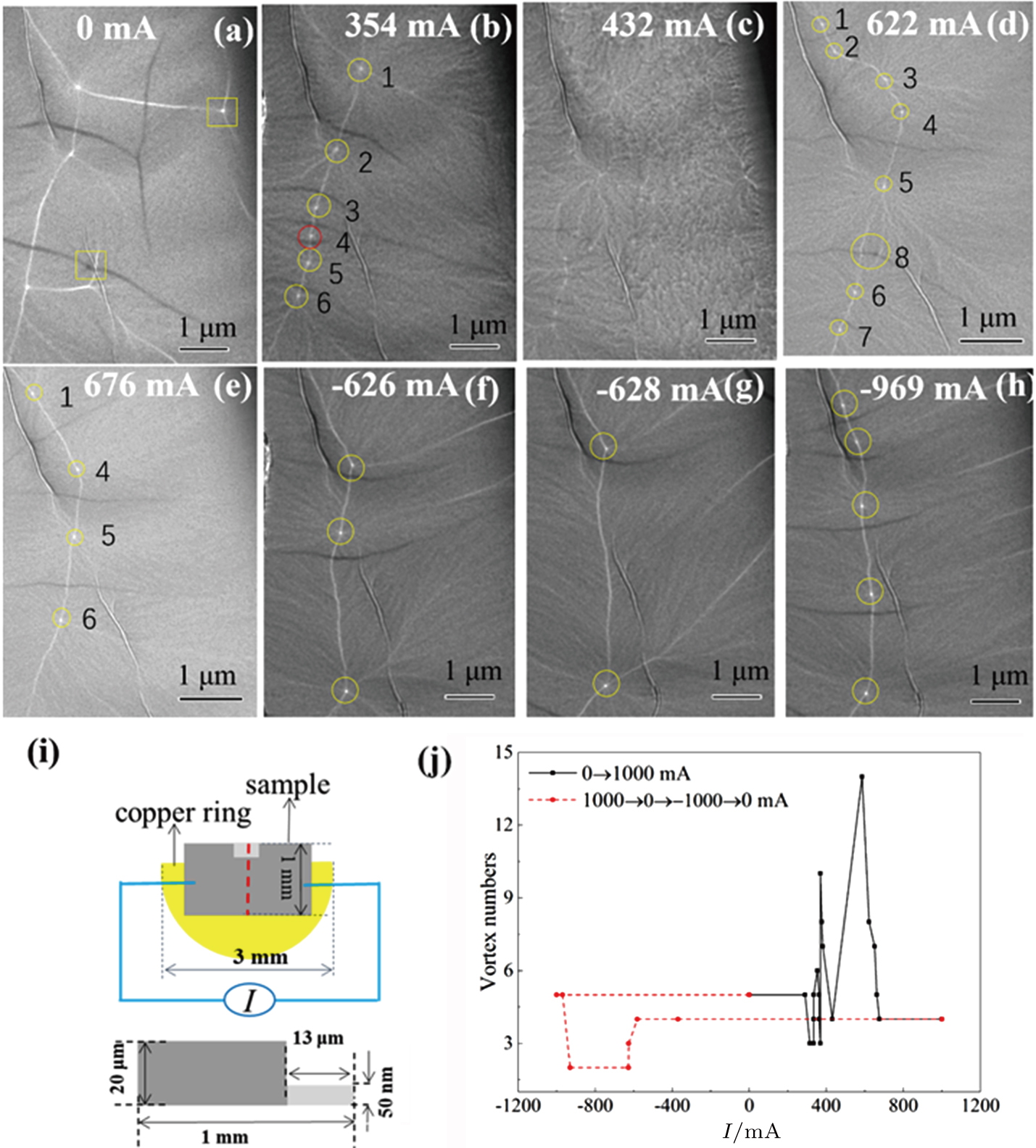
The V/AV propagation and nucleation/annihilation under electric current excitation observed via Lorentz TEM are shown in Fig. 8, with the schematic current-driven microdevice in Fig. 8(i). An individual vortex (marked by a yellow rectangle in Fig. 8(a)) moves towards the edge and disappears (Fig. 8(b)) with increasing electric current. The contrast of the magnetization ripple changes significantly and almost all the vortices completely annihilate at 432 mA (Fig. 8(c)), indicating the magnetization transition process. The vortices and anti-vortices nucleate again with further increasing the current to 622 mA (Fig. 8(d)) and become a stabilized cross-tie DW at 676 mA (Fig. 8(e)). The vortices and anti-vortices annihilate under a reversed electric current (Figs. 8(f)–7(g)) and then re-nucleate (Fig. 8(h)) at 969 mA, which remains stabilized even after the electric current is switched off. The summarized curves (Fig. 8(j)) indicate the numbers of vortex cores versus current. The in-plane magnetization change is presented via the changing ripples and vague vortex cores due to the strong interactions between electric current and magnetic moments while increasing electric current. This real-space observation of the nucleation and annihilation behaviors under electric current provides a fruitful playground for fundamental physics and the exploration of the novel application of accumulated rare-earth resources.[61]
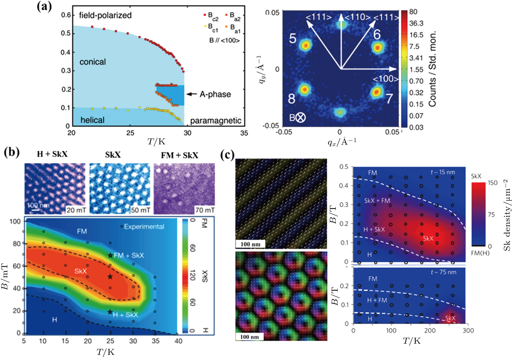
3.2. Magnetic skyrmion generation and manipulationMagnetic skyrmions were originally introduced by the British physicist Tony Skyrme to describe localized, particle-like configurations in the field of pion particles.[63] In recent years, a skyrmion crystal (SkX) with a non-centrosymmetric B20 cubic structure was experimentally identified for the first time in a helimagnet MnSi by small-angle neutron scattering (SANS) measurements. In the ground state, the magnetic structure shows a proper screw structure with a periodicity of ∼ 19 nm, which is induced by Dzyaloshinskii–Moriya interaction (DMI) originating from the symmetry-broken structure. When an external magnetic field is applied, SkX with six-fold symmetry emerges perpendicular to the external magnetic field as shown in Fig. 9(a).[11] However, the magnetization configuration in real space is not feasible using SANS. Lorentz TEM imaging together with TIE method clearly shows the spin configuration of skyrmions and prompts the overwhelming study since the first demonstration in thin plates of helimagnets Fe0.5Co0.5Si (Fig. 9(b)).[19] Later, skyrmions were discovered in several magnetic alloys with the same asymmetric B20 structure.[12,64,65] Among them, FeGe (Fig. 9(c)) has the highest Curie temperature of about 278 K near room temperature.[12,66] Recent studies have revealed different manipulations to stabilize skyrmions in terms of temperature and magnetic field range for prompting its application. When the plate thickness (15 nm) is smaller than the helical period, i.e. a magnetically two-dimensional (2D) state, the T–B skyrmion phase window is broadened as shown in Fig. 9(c) in comparison to the original limited temperature range of B20 compounds. The realization of room-temperature skyrmions and the current-driven behavior is critical for its practical application in information storage and logic technologies, therefore, the exploration for new material and external-field manipulations have always drawn significant attention.[6,58,67–69]
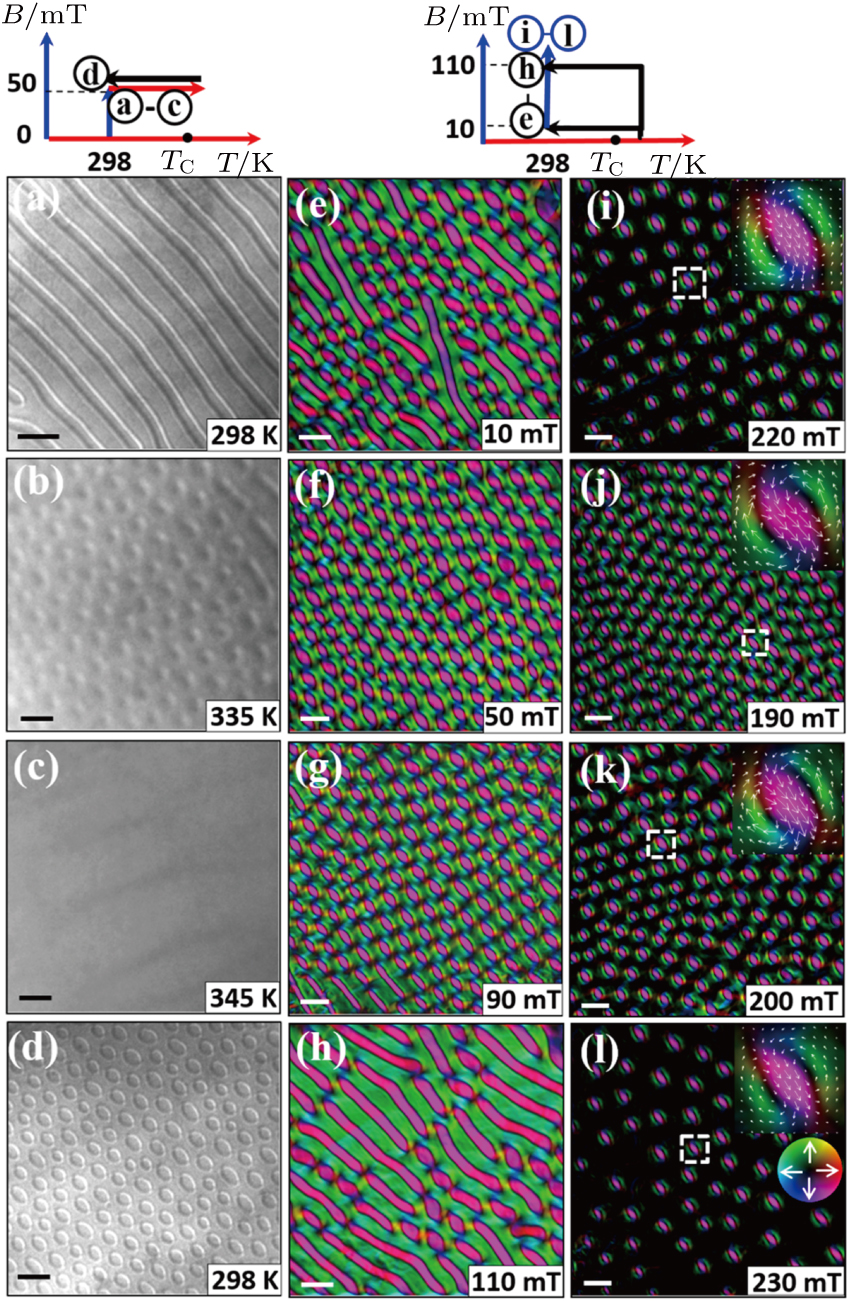
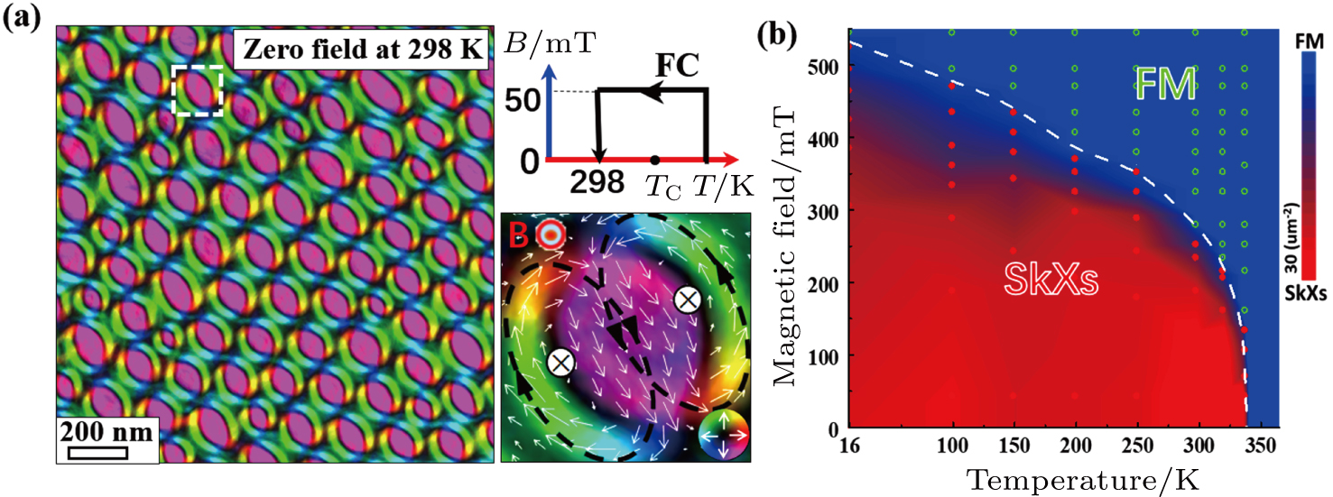
3.2.1. Magnetic skyrmions in bulk magnetsUp to now, numerous magnetic materials hosting skyrmions,[14,66,70] which could be generated via different mechanisms including the dominated symmetry-broken DMI and dipolar interactions, have been discovered. Using Lorentz TEM, biskyrmion spin configuration is identified over a wide temperature range of 16 K–340 K in hexagonal centrosymmetric (Mn1−xNix)65Ga35 (x = 0.5) (MnNiGa) alloy. The biskyrmion evolution from ground stripe domains is clearly demonstrated in Fig. 10.[71] The overall skyrmion distribution in terms of temperature and magnetic field (Fig. 10(i)) exposes the indispensable requirement of magnetic field for equilibrium skyrmion phase and less biskyrmion density away from TC. Field-cooling (FC) manipulation has shown effective in extending skyrmions to a wider temperature and magnetic field range. Metastable SkX state is extended below the equilibrium SkX temperature range via FC manipulation evidenced by neutron diffraction and Hall resistivity measurements in β-Mn-type Co8Zn8Mn4 [64] and MnSi,[72] respectively. However, the nontrivial zero-field skyrmions cannot be obtained in the equilibrium range via FC in the above skyrmion materials and the indirect detection methods do not depict the dynamic behavior. The in situ Lorentz TEM observation gives clear images depicting the generation and sustainability of the robust field-free biskyrmion lattice via appropriate FC manipulation from above TC in centrosymmetric MnNiGa alloy as shown in Fig. 11. The nucleation of biskyrmion phase is energetically favored under appropriate magnetic field while cooling across TC; the topological protection and the increased energy barrier help to stabilize biskyrmion phase without transforming into stripe domains. The detailed magnetic evolution under different FC procedures are shown in Fig. 12, which demonstrates that the magnetic field strength during FC plays a critical role, and the optimum magnetic field strength to generate highest-density biskyrmions is obtained by comparing the biskyrmion densities in presence of too strong and weak fields.[18] The high-density zero-field biskyrmion lattice sustains over the whole temperature range of 16 K–338 K (Fig. 11(b)) after the optimized FC manipulation, promoting the potential applications in nonvolatile memory devices.
3.2.2. Magnetic skyrmions in multilayersTremendous progress about exploring new skyrmion materials has been made in the multilayer thin film since the discovery of the blowing skyrmion behavior via electric currents in a sandwiched Ta/CoFeB/TaO multilayer with interfacial DMI.[73] Room temperature skyrmions, with their electric field-driven behavior and compatibility with current spintronic fabrication techniques in thin films can be readily integrated into the spintronic devices. The skyrmion characterization and dynamic behavior can be studied using various instruments. For example, writing and deleting a single skyrmion is studied using spin-polarized tunneling currents at low temperatures using spin-polarized scanning tunneling microscopy (SP-STM).[74] Blowing out room-temperature skyrmions due to electrical currents are observed using skyrmion Hall effect by magneto-optical Kerr effect (MOKE).[73,75] Artificial skyrmions are detected due to the interlayer coupling in thin films by scanning electron microscopy with polarization analysis (SEMPA).[76]
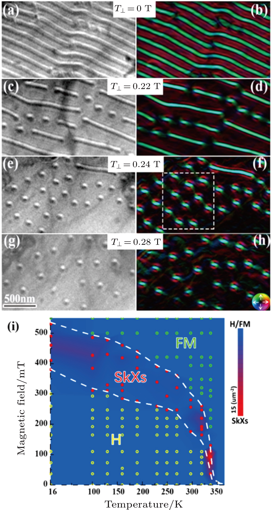
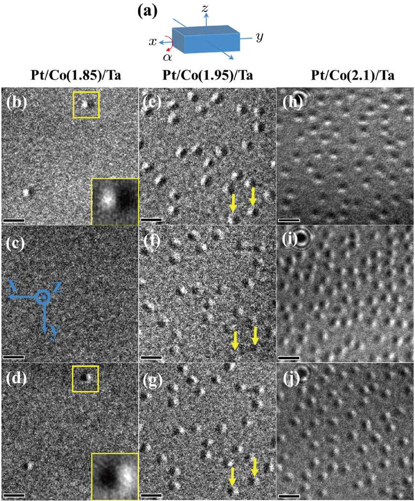
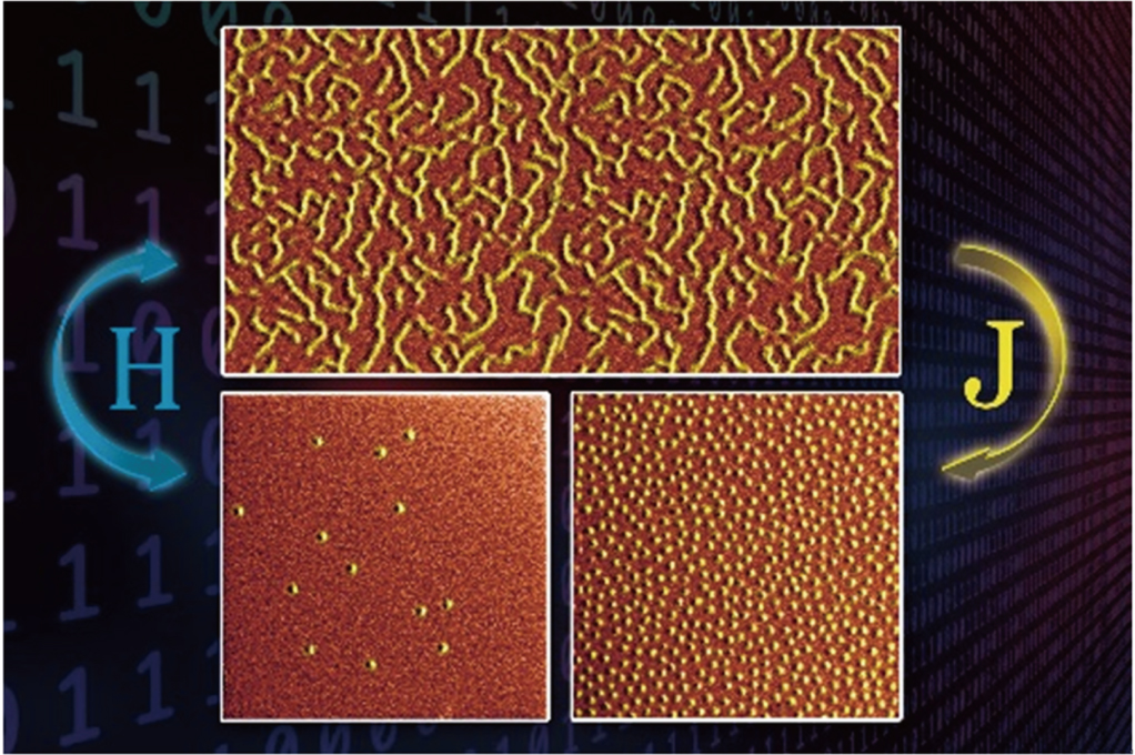
Lorentz TEM has advantages in demonstrating the spin configuration and dynamic behavior of nanometric magnetic domains under different external fields. The spin configuration of typical Néel-type skyrmions in multilayers can be identified by tilting the specimen based on the magnetic field-induced beam deflection and the contrast mechanism of Lorentz TEM, which can be summarized as the disappearance of contrast at a position and reversal of contrast at relatively opposite angles.[68,77] Moreover, the multilayers sputtered on the Si3N4 membrane windows for direct TEM observation avoid the extrinsic features introduced by additional TEM preparation. Néel-type magnetic skyrmions were successfully identified in Ta(4)/[Pt(3)/Co(1.85)/Ta(3)]6 multilayers based on their response to opposite tilting angle of 18° as shown in Figs. 13(b)–13(d).[78] By increasing Co layer thickness to alter the anisotropy, only a few Néel-type skyrmions could be identified, as marked by yellow arrows in Figs. 13(e)–13(g), using the same tilting procedure.[78] The consistent contrast regardless of any tilting angle indicates non-ideal Néel-type skyrmions as shown in Figs. 13(e)–13(j). Figure 14 shows the sub-50-nm skyrmion distribution with and without electromagnetical manipulation in Ta(4)/[Pt(3)/Co(1.85)/Ta(3)]6 multilayers,[79] where the skyrmion density is tunable and can be significantly enhanced by electromagnetical manipulation as compared to the skyrmions density directly induced via magnetic field. Remarkably, these high-density skyrmions sustain at zero field due to the optimized manipulation after both the in-plane current and perpendicular magnetic fields are switched off.
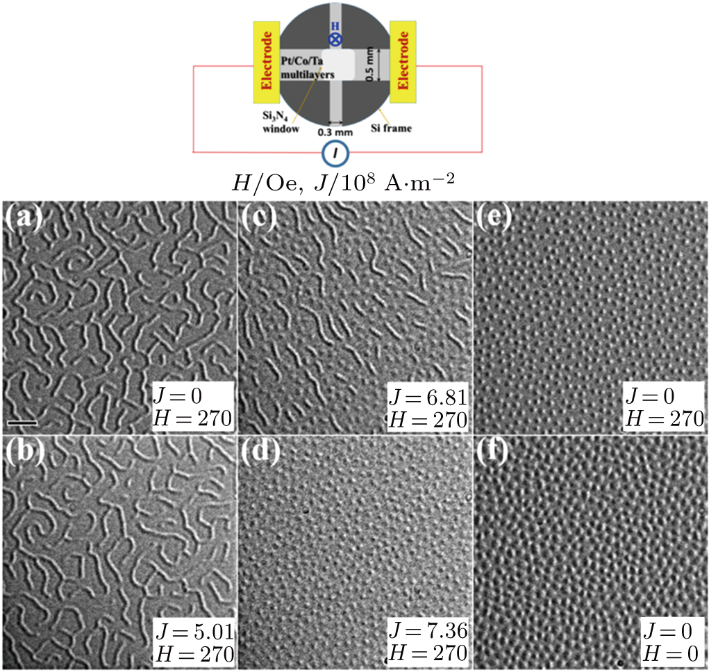
Figure 15 demonstrates the different magnetic domain distributions owing to the different electromagnetic effects under the same magnetic field of 270 Oe but different electric current densities. The real-space observation of zero-field magnetic skyrmions in the multilayers at room temperature promotes skyrmions in practical applications.
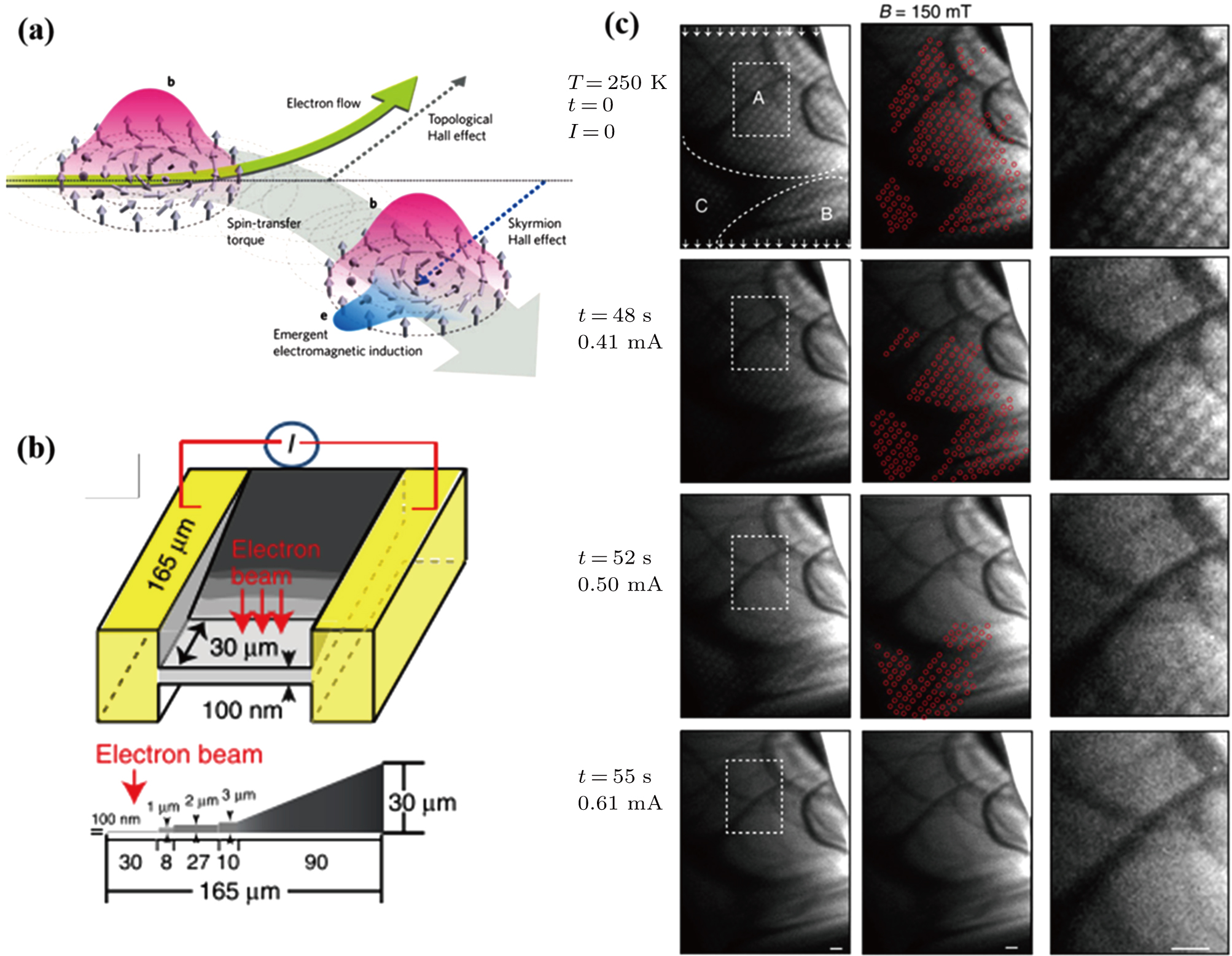
3.2.3. Magnetic skyrmions driven by electric currentsElectron spins play a critical role and contribute differently in functional magnetic materials. In 2008, Parkin et al. proposed that the polarization current drives the domain wall movement via spin transfer torque effect, thereby realizing the information reading and writing in the racetrack memory.[80] From the aspect of device application, dynamic current-driven motion of magnetic skyrmion is superior to the normal domain wall due to the lower current density requirements. The interactions between the traversed electrons and the topological skyrmions give rise to the topological Hall effect. As a counteraction of the topological Hall effect related to the electron Hall motion, the skyrmion or SkX itself exhibits a Hall motion.[6] Similar to the FM domain wall motion driven by spin-polarized electric current, the flowing electric current drives the skyrmions not only along the electron flow direction but also along the transverse (Hall) motion as shown in Figs. 16(a).[6] Figures 16(b) and 16(c) show current-flow dynamics captured from in situ Lorentz TEM movie based on the perpendicular magnetic field of 150 mT applied to generate skyrmion crystal.[12] Skyrmions in region A start to move at an applied current of 0.41 mA, then the skyrmions in region B move at a current of 0.50 mA. As the current further increases, up to 0.61 mA, skyrmions are no longer static over the whole region. An electric current of 1 mA corresponds to a current density of ∼ 65 A⋅cm−2. Skyrmion-based devices with such low-current controllability could be further explored for next-generation spintronics.
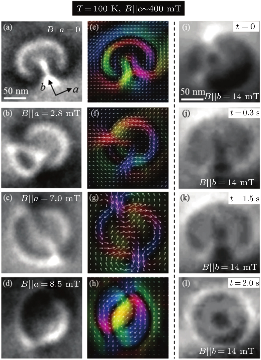
3.3. Topological spin configuration of magnetic bubbles in La1−xSrxMnO3 and MnNiGaYTraditional magnetic bubble domains were studied as early as 1970 with the corresponding information storage device commercialized at that time.[81,82] With the development of high-resolution techniques, the detailed spin configuration inside the domain wall and the discovery of nanometer bubbles led to a new surge of research interests. The topological states of traditional magnetic bubbles are usually various and random, as shown in Fig. 17, depending on the defects and orientations of the BLs inside the domain wall. Hence, the topological number can be 2, 1, or 0 for the magnetic bubbles with different internal structures or the configuration of BLs. The BL inside the bubble domain wall is very sensitive to the excitations from magnetic field. By using in situ Lorentz TEM imaging, the magnetization dynamics through the BL motion were clearly depicted in La1−xSrxMnO3 (LSMO) (x = 0.15–0.2) as shown in Fig. 17. Figure 17(a)–17(d) show the motion of the BLs along the bubble domain wall, accompanied by the deformation of the bubble under the in-plane magnetic field along the a axis. Under the influence of the applied magnetic field, the initial state of magnetic bubbles changes withholding different topological numbers as shown in Figs. 17(a)–17(d), Lorentz TEM images in Figs. 17(i)–17(l) demonstrate the temporal evolution of magnetization accompanied by annihilation of BLs for a selected magnetic bubble under a fixed in-plane magnetic field. A successive evolution within 2.0 s is clearly recorded including the initial generation of a pair of BLs inside the bubble domain wall, the movement of the bubble wall, and the final annihilation. Therefore, in situ Lorentz TEM has good capability of analyzing the spin configuration and providing evidence for the topological transitions driven by external fields and time.[14]
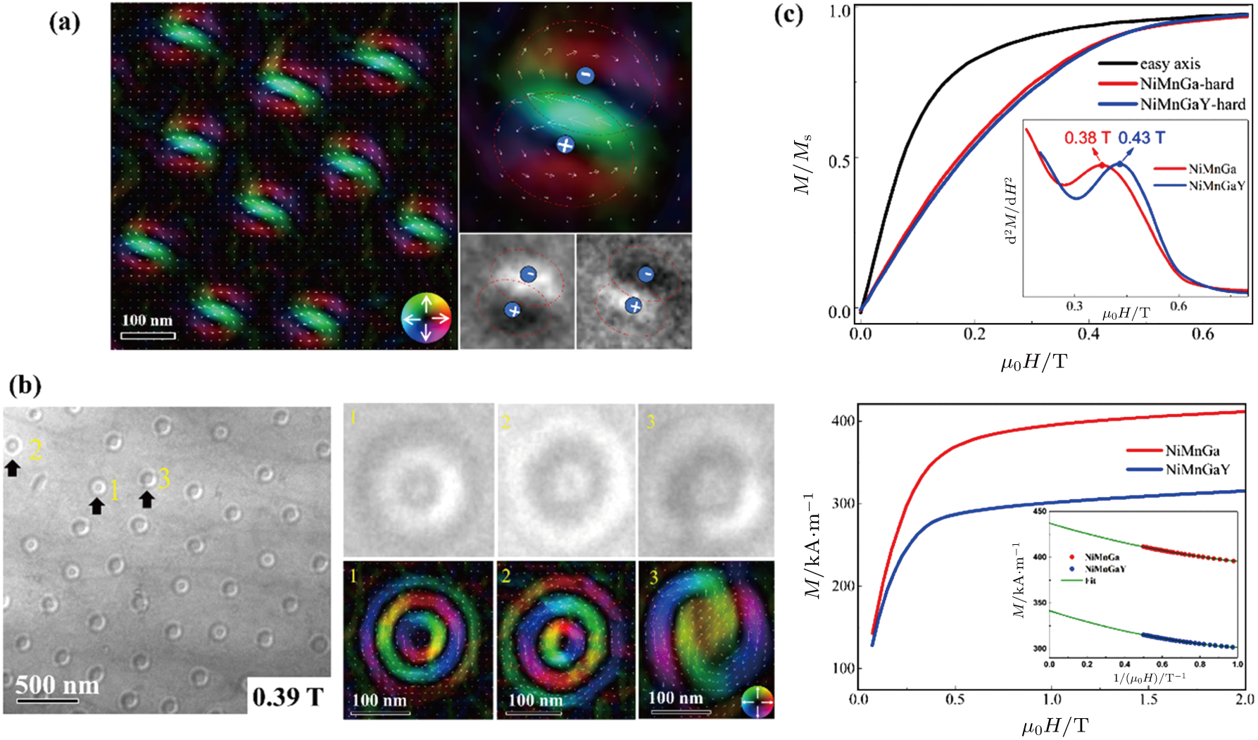
Despite the complex spin configuration in the above-mentioned narrow domain wall region, the domain morphology favors the inside magnetization direction along the easy-axis, which usually requires the quality factor Q (Q = Ku/Kd = μ0Hk/μ0Ms) larger than 1. The enhancement of quality factor Q caused by the substitution of rare-earth element Y in MnNiGa contributes to the transition from biskyrmions to bubbles as shown in Fig. 18. The biskyrmion spin configuration composed of two single skyrmions with opposite magnetic helicities in MnNiGa is demonstrated in Fig. 10 and discussed in Subsection 3.2.[71] Lorentz TEM images identify the magnetic bubbles with random distribution of different spin configurations (Fig. 18(b)) in clear comparison with uniform biskyrmions (Fig. 18(a)) although other magnetic properties like TC do not change much due to the slightly substituted rare earth Y. The magnified in-plane magnetization textures via TIE analysis demonstrate bubbles “1, 2” with clockwise and counterclockwise winding spins in three concentric rings and bubble “3” with a pair of Bloch lines. To explore the intrinsic nature of the topological transition, the effective uniaxial anisotropy field Hk and the saturated magnetization Ms for MnNiGa and MnNiGaY are measured as shown in Fig. 18(c). Substitution of Y leads to a drop in the calculated stray field energy Kd from 119.1 kJ⋅m−3 to 74.8 kJ⋅m−3 and uniaxial anisotropy Ku from 82.70 to 74.20 kJ⋅m−3. Therefore, the overall quality factor Q increases from 0.69 for MnNiGa to 0.99 for MnNiGaY, which explains the origin of the spin configuration transition from biskyrmions to bubbles well.[83] These novel magnetic textures directly observed by real-space Lorentz TEM may encourage further exploration of new materials with skyrmionic bubbles in accordance with the magnetic parameters.


