† Corresponding author. E-mail:
Project supported by the Chinese Academy of Sciences–The World Academy of Sciences (CAS–TWAS) Fellowship Program, the National Basic Research Program of China (Grant Nos. 2015CB921403 and 2012CB933102), and the National Natural Science Foundation of China (Grant Nos. 51427801, 11374350, and 11274361).
We present a systematic investigation of magnetic anisotropy induced by oblique deposition of Co thin films on MgO (001) substrates by molecular beam epitaxy at different deposition angles, i.e., 0°, 30°, 45°, 60°, and 75° with respect to the surface normal. Low energy electron diffraction (LEED), surface magneto–optical Kerr effect (SMOKE), and anisotropic magnetoresistance (AMR) setups were employed to investigate the magnetic properties of cobalt films. The values of in-plane uniaxial magnetic anisotropy (UMA) constant Ku and four-fold magnetocrystalline anisotropy constant K1 were derived from magnetic torque curves on the base of AMR results. It was found that the value of Ku increases with increasing deposition angle with respect to the surface normal, while the value of K1 remains almost constant for all the samples. Furthermore, by using MOKE results, the Ku values of the films deposited obliquely were also derived from the magnetization curves along hard axis. The results of AMR method were then compared with that of hard axis fitting method (coherent rotation) and found that both methods have almost identical values of UMA constant for each sample.
The surface morphology and microstructure of thin films have a direct impact on the magnetic anisotropy. There are two main sources of magnetic anisotropy: one is spin–orbit interaction, which causes magnetocrystalline anisotropy (MCA) and the other is dipolar interaction, which causes shape anisotropy.[1,2] The study and tuning of anisotropy in magnetic thin films have attracted much attention because of its applications in data storage devices and magnetoresitive devices. To improve the storage capability of these devices, a highly uniaxial magnetic anisotropy (UMA) is required. Especially, in magnetoresistive random access memory and head assemblies of the hard drivers, in-plane UMA is required.[3] Different methods, such as oblique deposition[4] applying a magnetic field during deposition,[5] increasing the substrate temperature[6] and post-annealing (annealing in the presence of the magnetic field), have been adopted to induce the magnetic anisotropy.[7] The effect of oblique deposition on the magnetic anisotropy has long been established.[8,9] It is known that shadowing and steering effect, in the case of oblique deposition, leads to elongated grain structure or ripples. These elongated grain structures and ripples induce in-plane UMA.[10]
Different techniques such as ferromagnetic resonance (FMR)[11] magnetic hysteresis loop measurement, torque measurement[12] rotational magneto-optic Kerr effect (ROT-MOKE)[13] magnetic transverse biased initial inverse susceptibility and torque (TBIIST)[14] have been adapted to manipulate the magnetic anisotropy. It is known for ultra-thin films that the coherent domain rotation magnetization reversal does not always happen, particularly when the applied field is lower than the saturation field. Therefore, it is difficult to distinguish the detailed information regarding the magnetic anisotropy accurately from the magnetization hysteresis loops. On the other hand, magnetotransport technique has been suggested to be a powerful technique for magnetic anisotropy in thin single layer films by AMR[15–20] This can be acquired by applying an appropriately large field to ensure a true single-domain rotation.
Co/MgO system is the point of our interest because of its application in magnetoelectronics. A lot of studies have been done in the past on the growth behavior and the structure of Co film on the MgO (001) substrate. However, magnetic properties of Co film on MgO (001) have not been studied in detail. In this paper the magnetic anisotropy constants of Co ultra-thin films obliquely deposited on MgO (001) substrates have been determined by using MOKE and AMR techniques.
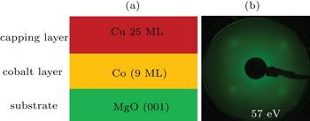
Experiments were performed in the molecular beam epitaxy (MBE) system with a base pressure of 2.0 × 10⁻¹⁰ mbar. Crystalline polished MgO (001) substrates were used for the deposition of Co films. As the surface of the commercially available MgO substrate is contaminated by water and carbon, the substrates were first annealed in the ultra-high vacuum chamber at 700 °C for about 2 h to remove the carbon contamination. After annealing the substrates, low energy electron diffraction (LEED) pattern was studied using the LEED system to confirm the surface cleanliness. Ultra-thin Co films were then deposited at room temperature and at different angles with respect to surface normal using an electron beam evaporator. The thicknesses of all the five samples were kept constant (9 ML) that were achieved by increasing the growth time with increasing the deposition angle. Before taking out the samples from the vacuum chamber, copper (Cu) films of about 25 ML were caped to avoid the oxidation of the samples. The corresponding magnetic hysteresis loops were measured by MOKE with azimuthal rotation to measure the oblique deposition-induced uniaxial anisotropy. The angular dependence AMR measurement setup with a standard four-point method was used to determine the values of magnetic anisotropy constants at room temperature for obliquely deposited Co thin films on MgO (001) substrates.
Figure
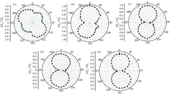
During the oblique deposition a self-shadowing effect takes place, resulting in the formation of grains in the plane of the film that is elongated perpendicular to the incident flux direction and with an aspect ratio increasing at a larger deposition angle. Therefore, the inhomogeneous distribution of the adatoms (roughness) occurs. This in-plane Ku with easy axis perpendicular to the incident flux direction is actually induced by the roughness due to the oblique deposition. Therefore, as the incidence angle increases the roughness is increased causing the increase in the magnitude of Ku,[2,3] as shown in Figs.
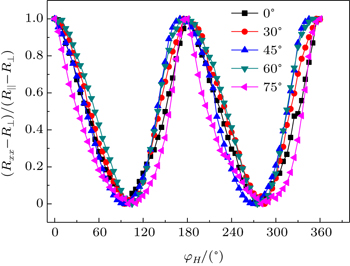
We determined the values of the magnetic anisotropy constants for all of the samples from the torque curves using AMR measurements. The AMR can be expressed as


The second is the torque due to the crystal structure of the sample acting to rotate the magnetization towards the easy axis


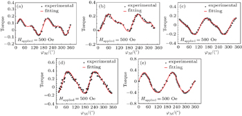
The values of Ku were determined by fitting the normalized magnetic torque curves with Eq. (
The determined values of UMA constant (Ku) and MCA constant (K1) for all the samples as a function of deposition angles are shown in Fig.
 | Fig. 5. UMA (Ku) and MCA (K1) as functions of the deposition angle (a) and the applied field for normally deposited film (b) and 60° obliquely deposited film (c), respectively. |
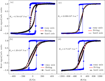
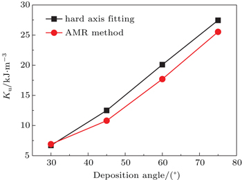
Further, we have calculated the values of UMA for all samples deposited by oblique deposition at different angles, using MOKE data applying hard axis fitting method. Ignoring the relatively weak MCA, the total magnetic energy is given as


In summary, the in-plane UMA Ku induced by oblique deposition shows an increasing behavior with the deposition angle while K1 shows an invariant behavior. The values of MCA constant K1 and UMA constant Ku exhibit almost a linear behavior with the applied field. The results of AMR method and MOKE have almost identical values of UMA for each sample.
| 1 | |
| 2 | |
| 3 | |
| 4 | |
| 5 | |
| 6 | |
| 7 | |
| 8 | |
| 9 | |
| 10 | |
| 11 | |
| 12 | |
| 13 | |
| 14 | |
| 15 | |
| 16 | |
| 17 | |
| 18 | |
| 19 | |
| 20 | |
| 21 |


