Liu Chun-Xiao, Chen Meng, Fu Li-Li, Zheng Rui-Lin, Guo Hai-Tao, Zhou Zhi-Guang, Li Wei-Nan, Lin She-Bao, Wei Wei. Planar waveguides in neodymium-doped calcium niobium gallium garnet crystals produced by proton implantation. Chinese Physics B, 2016, 25(4): 044211
Permissions
Planar waveguides in neodymium-doped calcium niobium gallium garnet crystals produced by proton implantation
Liu Chun-Xiao1, †, , Chen Meng1, Fu Li-Li2, Zheng Rui-Lin1, Guo Hai-Tao3, Zhou Zhi-Guang3, Li Wei-Nan3, Lin She-Bao4, Wei Wei1, ‡,
School of Optoelectronic Engineering, Nanjing University of Posts and Telecommunications, Nanjing 210023, China
College of Electronic Science and Engineering, Nanjing University of Posts and Telecommunications, Nanjing 210023, China
State Key Laboratory of Transient Optics and Photonics, Xi’an Institute of Optics and Precision Mechanics, Chinese Academy of Sciences, Xi’an 710119, China
Institute of Physics & Optoelectronics Technology, Baoji University of Arts and Sciences, Baoji 721007, China
Project supported by the National Natural Science Foundation of China (Grant Nos. 11405041, 61405240, 61077070, 61177086, 51002181, and 61177084), the Scientific Research Starting Foundation for New Teachers of Nanjing University of Posts and Telecommunications (NUPTSF) (Grant No. NY214159), and the Research Center of Optical Communications Engineering & Technology, Jiangsu Province, China (Grant No. ZSF0401).
Abstract
Abstract
In this work, the fabrication and optical properties of a planar waveguide in a neodymium-doped calcium niobium gallium garnet (Nd:CNGG) crystal are reported. The waveguide is produced by proton (H+) implantation at 480 keV and a fluence of 1.0×10¹⁷ ions/cm2. The prism-coupling measurement is performed to obtain the dark mode of the waveguide at a wavelength of 632.8 nm. The reflectivity calculation method (RCM) is used to reconstruct the refractive index profile. The finite-difference beam propagation method (FD-BPM) is employed to calculate the guided mode profile of the waveguide. The stopping and range of ions in matter 2010 (SRIM 2010) code is used to simulate the damage profile induced by the ion implantation. The experimental and theoretical results indicate that the waveguide can confine the light propagation.
Neodymium-doped calcium niobium gallium garnet (Nd:CNGG) is a kind of attractive laser crystal suitable for direct diode-pumping. It is a cubic crystal and belongs to the class of disordered crystal.[1] The crystal possesses the advantages of both Nd3+-doped glass and ordered crystals in some respects.[2] For example, it has a higher thermal conductivity than Nd3+-doped glasses and a broader pump absorption band than Nd3+-doped ordered crystals (such as Nd:YAG).[3] In view of the excellent optical properties, the Nd:CNGG crystal is a suitable candidate for fabricating a laser waveguide.
With the development of optical fiber communication and integrated optics, an optical waveguide, as a fundamental component of optoelectronics, has attracted more and more attention. It is characterized by a medium with a high refractive index surrounded by media with low refractive indexes.[4] Its basic principle to confine light propagation to dimensions on the order of micrometers is the internal total reflection occurring at the boundaries between guided cores and claddings. Although there are many methods to produce waveguides in optical materials, such as the diffusion of metal ions,[5] femtosecond laser inscription,[6] ion exchange,[7] sol–gel,[8] etc., the ion implantation is one of the most powerful techniques because of the wide applicability in materials and accurate control of both the penetration depth of implanted-ions and the concentration of dopants.[9,10] Therefore, combining outstanding optical properties of the Nd:CNGG crystal and the competitive waveguide technique of ion implantation to fabricate optical waveguides is an important research topic. Wang and Yu have fabricated planar waveguides in Nd:CNGG crystals by carbon ion implantation.[11] However, the penetration depth of proton is much larger than that of heavier ions (such as oxygen and carbon ions) for the same energy. This fact is especially advantageous for proton implantation when infrared light propagates in a waveguide. At the same time, the most characteristic wavelength of the emission spectrum in the Nd:CNGG crystal is about 1060 nm, which is in the near-infrared range. In the present work, we report on the preparation and optical characteristics of the planar waveguide in the Nd:CNGG crystal by H+ ion implantation.
2. Experiments and simulations
The Nd:CNGG crystal with an Nd3+ concentration of 0.5 at.% was grown by the Czochralski method. It was cut into pieces each with dimensions of 10.0 mm×5.0 mm×2.0 mm and they were optically polished prior to any experiment. Its density, measured by the Archimedes method, was 4.69 g/cm3. The refractive index of the crystal substrate measured by a Metricon 2010 Prism Coupler was 1.9858 at a wavelength of 632.8 nm.
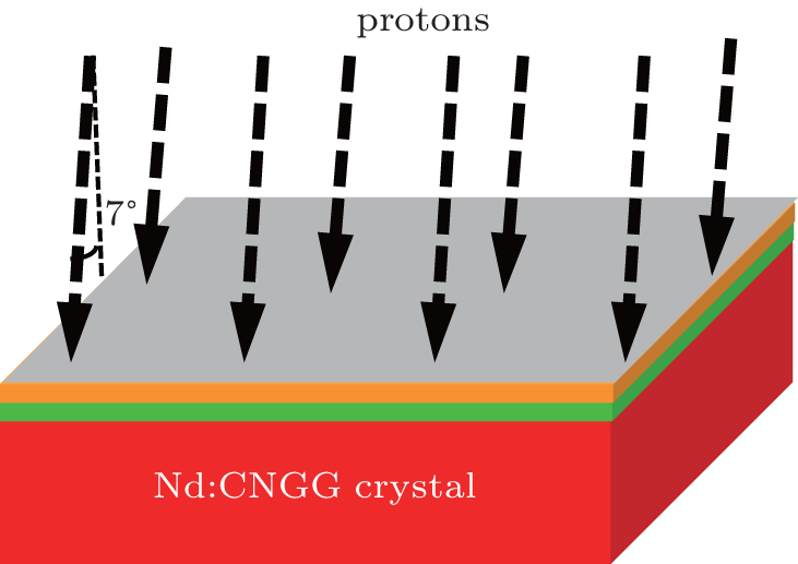
The crystals were placed in a vacuum chamber at a pressure of 10−6 Torr (1 Torr = 1.33322×10² Pa), and the implantation of the proton was carried out at room temperature by a 500-kV implanter at the Institute of Semiconductors of Chinese Academy of Sciences. Figure 1 illustrates schematically the waveguide fabrication process. The implantation energy and fluence were set to be 480 keV and 1.0×10¹⁷ ions/cm2, respectively. The angle of implantation was chosen to be 7° to avoid a channeling effect. The ion beam was scanned over an area of 10.0 mm×5.0 mm to ensure homogeneous implantation.
Fig. 1. Schematic diagram of the fabrication process of a planar waveguide in the Nd:CNGG crystal.
Prior to the irradiation, the fluorescence spectrum of the Nd:CNGG crystal and the fluorescence lifetime of the 4F3/2 Nd3+ laser manifold in the crystal were measured by an Edinburgh FLS920P spectrometer (Edinburgh, UK) equipped with a near-infrared photomultiplier at room temperature.
After the implantation, the guided modes of the optical waveguide were measured by the standard prism-coupling method (a prism coupler, Metricon 2010). During the measurement, a rutile prism was employed to couple an He–Ne laser light with a wavelength of 632.8 nm into the waveguide. The refractive index distribution and the near-field modal profile of the waveguide were simulated by the reflectivity calculation method (RCM) and the finite-difference beam propagation method (FD-BPM), respectively.
3. Results and discussion
3.1. Fluorescent properties of Nd:CNGG
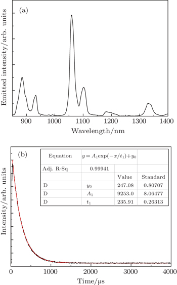
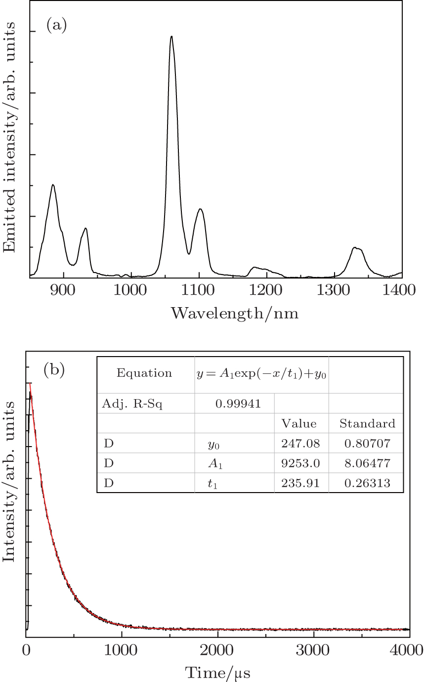
Figure 2(a) shows the fluorescence spectrum of the Nd:CNGG crystal under 800-nm Xe lamp excitation in a range of 850 nm–1400 nm. There are three major emission bands centered at about 884 nm for the 4F3/2 → 4I9/2 transition, 1060 nm for the 4F3/2 → 4I11/2 transition, and 1332 nm for the 4F3/2 → 4I13/2 transition, respectively.[12] Figure 2(b) shows the fluorescence decay curve at the 4F3/2 → 4I11/2 transition. The fluorescence lifetime of the Nd:CNGG crystal at the 4F3/2 → 4I11/2 transition is calculated by fitting the fluorescence decay curve with the single-exponential function and the value of the fluorescence lifetime is estimated to be about 235.9 μs. Therefore, the Nd:CNGG crystal possesses good laser performance, especially relatively long fluorescence lifetime.
Fig. 2. (a) Fluorescence spectrum and (b) decay curve of the Nd:CNGG crystal.
3.2. Waveguide characterization
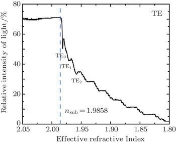
Figure 3 shows the dark mode spectrum of the proton-implanted waveguide in the Nd:CNGG crystal, obtained by the m-line prism coupling method for transverse electric (TE) polarization at a wavelength of 632.8 nm (Metricon 2010). The lack of reflected light results in a dip when the incident light is coupled into the waveguide region in the prism-coupling measurement process. The dip may correspond to a propagation mode. The sharper the dip is, the better the light confinement of the propagation mode becomes. There are three modes (TE0, TE1 and TE2) for the proton-implanted waveguide as shown in Fig. 3. Their corresponding effective refractive indices are 1.9815, 1.9705, and 1.9577, which are all less than the refractive index of the substrate (nsub = 1.9858). It means that a barrier-type waveguide is formed in the Nd:CNGG crystal after proton irradiation based on the previous researches.[13,14]
Fig. 3. Measured relative intensity of the light reflected from the prism versus effective refractive index for the Nd:CNGG waveguide formed by 480-keV H+ ion implantation at a fluence of 1.0×10¹⁷ ions/cm2 at room temperature.
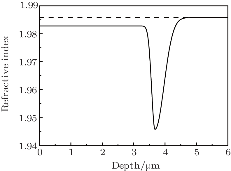
Figure 4 shows the reconstructed refractive index distribution as a function of the penetration depth of the implanted proton for the fabricated waveguide based on RCM.[15] In the reconstruction process, a conceivable function composed of two half-Gaussian curves is chosen for the index profile, which is characterized by a set of parameters. These parameters are adjusted until the calculated effective refractive indices match the measured ones within a satisfactory difference. The final profile is therefore assumed to approximately depict the refractive index distribution in the waveguide. The near-surface region (0 μm–3.28 μm) has a negative change on the refractive index, whilst an optical barrier with lower refractive index is built up at a depth of 3.65 μm inside the Nd:CNGG crystal. Compared with the refractive index of the substrate, the refractive indices in the near-surface region and at the optical barrier reduce about 0.16% and 2.01%, respectively. Therefore, the narrow layer between the crystal surface (air) and the barrier can act as a waveguide and confine light well. In Table 1, the calculated effective refractive indices of the three modes by RCM are 1.9811, 1.9760, and 1.9676, respectively, and the measured ones by the prism-coupling method are also listed in the table. The differences between the measured and calculated effective refractive indices are 4 × 10⁻⁴ for TE0, −5.5 × 10⁻³ for TE1 and −9.9 × 10⁻³ for TE2 respectively. Such small differences imply that the reconstructed refractive index profile is a reasonable distribution for the proton-implanted Nd:CNGG waveguide.
Fig. 4. Refractive index profile of the waveguide (solid curve) and refractive index of the substrate (dashed line).
Table 1.
Table 1.
Table 1.
Comparison between measured and calculated effective refractive indices for the proton implanted waveguide in the Nd:CNGG crystal.
.
Mode
Effective refractive index
Exp.
Cal.
Diff.
TE0
1.9815
1.9811
4.0×10⁻⁴
TE1
1.9705
1.9760
–5.5×10⁻³
TE2
1.9577
1.9676
–9.9×10⁻³
Table 1.
Comparison between measured and calculated effective refractive indices for the proton implanted waveguide in the Nd:CNGG crystal.
.
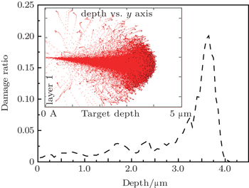
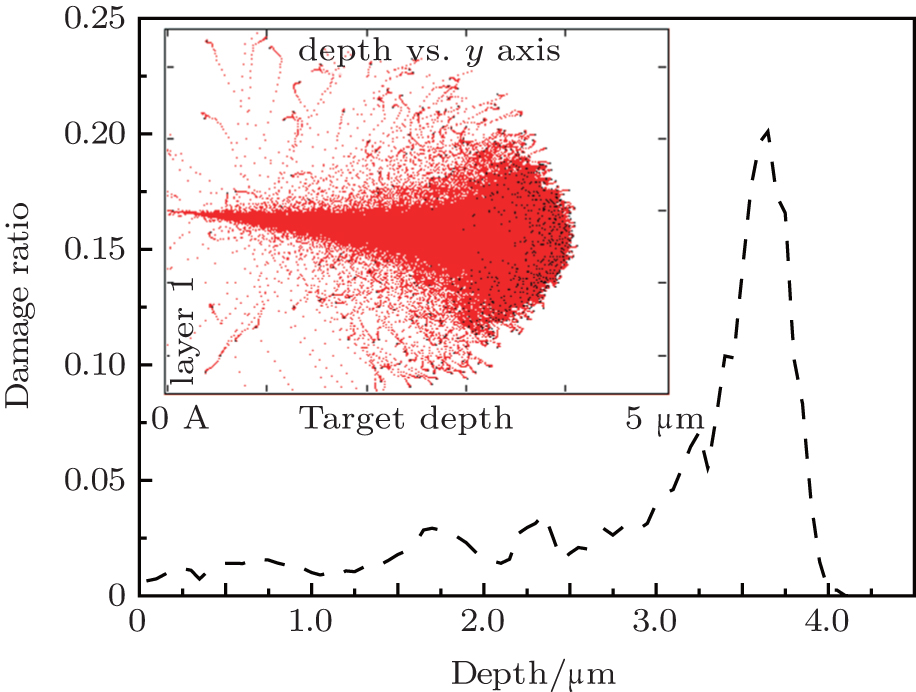
The lattice damage caused by ion implantation plays an important role in the change of the refractive index of the ion-implanted waveguide. The stopping and range of ions in matter 2010 (SRIM 2010) code[16] is the most widely used calculation method to simulate the process of ion implantation based on the Monte-Carlo method. Figure 5 shows the damage profile of the Nd:CNGG crystal implanted by 480-keV H+ ions with a fluence of 1.0×10¹⁷ ions/cm2 and the lateral straggling of the implanted ions simulated by SRIM 2010. There is an obvious damage peak at the end of the implanted proton track in Fig. 5, which is in good agreement with the deposition position of the implanted ions in the inset in Fig. 5. As indicated in most ion-implanted waveguide structures, the damage results in a little lattice disorder and a slight reduction of physical density.[17–19] Therefore, the refractive index at about 3.65 μm below the surface decreases and the optical barrier is formed.
Fig. 5. Damage ratio as a function of penetration depth of 480-keV proton in the Nd:CNGG crystal. The inset shows the lateral straggling of the implanted protons.
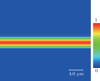
FD-BPM is a competitive technique for simulating the propagation of light in optical waveguides.[20] Figure 6 shows the two-dimensional modal intensity profile of the TE0 mode in the fabricated waveguide, which was calculated by the FD-BPM at a wavelength of 632.8 nm. The simulation is based on the refractive index profile in Fig. 4. The simulation results indicate that the waveguide can restrict the light propagation well as shown in Fig. 6.
Fig. 6. Simulated near-field light intensity distribution of TE0 mode for the proton-implanted Nd:CNGG waveguide.
4. Conclusions
In this work, optical planar waveguides in Nd:CNGG crystals are fabricated by 480-keV proton implantation with a fluence of 1.0×10¹⁷ ions/cm2. According to the m-line spectrum and the reconstructed refractive index profile, the waveguide is a barrier-confined structure at a wavelength of 632.8 nm. The simulation of FD-BPM suggests that the light of the TE0 mode can be well confined in the waveguide region.


 , Chen Meng1, Fu Li-Li2, Zheng Rui-Lin1, Guo Hai-Tao3, Zhou Zhi-Guang3, Li Wei-Nan3, Lin She-Bao4, Wei Wei1, ‡,