


Giant magnetic moment at open ends of multiwalled carbon nanotubes*
Cite this Article
Wang Gang, Chen Min-Jiang, Yu Fang, Xue Lei-Jiang, Deng Ya, Zhang Jian, Qi Xiao-Ying, Gao Yan, Chu Wei-Guo, Liu Guang-Tong, Yang Hai-Fang, Gu Chang-Zhi, Sun Lian-Feng. Giant magnetic moment at open ends of multiwalled carbon nanotubes* . Chinese Physics B, 2014, 24(1): 016202 
Permissions
Giant magnetic moment at open ends of multiwalled carbon nanotubes*
These authors contributed equally to this work.
Corresponding author. E-mail: wangg@nanoctr.cn
Corresponding author. E-mail: slf@nanoctr.cn
Project supported by the National Natural Science Foundation of China (Grant Nos. 10774032 and 51472057) and the Instrument Developing Project of the Chinese Academy of Sciences (Grant No. Y2010031).
Abstract
The attractions of cantilevers made of multiwalled carbon nanotubes (MWNTs) and secured on one end are studied in the non-uniform magnetic field of a permanent magnet. Under an optical microscope, the positions and the corresponding deflections of the original cantilevers (with iron catalytic nanoparticles at the free end) and corresponding cut-off cantilevers (the free ends consisting of open ends of MWNTs) are studied. Both kinds of CNT cantilevers are found to be attracted by the magnet, and the point of application of force is proven to be at the tip of the cantilever. By measuring and comparing deflections between these two kinds of cantilevers, the magnetic moment at the open ends of the CNTs can be quantified. Due to the unexpectedly high value of the magnetic moment at the open ends of carbon nanotubes, it is called giant magnetic moment, and its possible mechanisms are proposed and discussed.
Keyword:
62.20.–x; 68.35.Gy; 75.50.Dd; carbon nanotubes; open ends; giant magnetic moment
1. Introduction
Experimental reports of ferromagnetism in graphite, [1– 5] carbon nanotubes, [6, 7] graphene, [8] and other carbon-based materials[9, 10] have attracted intense interest because only s/p electrons are present, in contrast to the more familiar ferromagnetism based on 3d/4f electrons. In the experimental reports, three techniques were usually used: magnetic force microscopy (MFM), [2– 5] bulk XMCD (x-ray magnetic circular dichroism), [3] and magnetization measurements.[4– 9] With the technique based on MFM, it has been difficult to get quantitative results, due to the lack of geometry, magnetic properties of the tip and the material under investigation. Meanwhile, to avoid the effect of long-range van der Waals forces, the tip usually works in lift mode at a height of 50 nm, which causes low spatial resolution of the location of the magnetic signal. For the technique with magnetization measurements, it is important to know the exact contents of magnetic components[1] or make sure the sample is free of magnetic impurities, due to the extremely small measured magnetization.[9] XMCD is powerful to study the local magnetic moment associated with different elements in a sample, [3] and it can exclude the effect of magnetic impurities and achieve a spatial resolution of 50 nm.
2. Experimental section
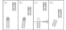
In this work, a different technique shown in Fig. 1 is used to study the attraction and deflection of a CNT cantilever in the non-uniform magnetic field of a permanent magnet. A bundle of multiwalled carbon nanotubes is fixed to a substrate at one end, leaving the other end free (an “ original” CNT cantilever). When the magnet is moved toward the CNT cantilever, the attraction and deflection of the cantilever can be observed and measured under an optical microscope. After the tip part of the cantilever is cut off, leaving the open ends on the CNTs, the CNT cantilever is still attracted and deflected in the non-uniform magnetic field. The point of application of the attractive force is demonstrated to be at the tip of the cantilever. By comparing the forces between the original and cut-off CNT cantilevers, the areal density of the magnetic moment at the open ends of the CNTs is obtained.
 | Fig. 1. A multiwalled carbon nanotube is used to represent the CNT cantilever for clarity. (a) A multiwalled nanotube with a catalytic nanoparticle at its tip (an “ original” CNT cantilever). The magnet is away from the CNT. (b) When the magnet is moved near the CNT, the attraction of CNT is observed. (c) and (d) If the tip of CNT is cut off (cut-off cantilever), leaving the CNT with an open end, the CNT is still attracted and deflected in the non-uniform magnetic field. The point of application of the attractive force is demonstrated to be at the tip of the cantilever. By comparing the forces between an original and cut-off CNT cantilevers, the areal density of the magnetic moment at open ends of CNTs is obtained. |
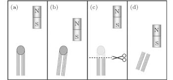
The CNT array (height ∼ 1 mm) used in this work was grown by chemical vapor deposition.[11, 12] The nanotubes in the array are multiwalled carbon nanotubes and have diameters of about 20 nm (Fig. 2). In the middle part of the CNT array, there is no signal of iron found, as indicated by EDX (electron dispersion x-ray) analyses (Figs. 2(c) and 2(d)). The growth mechanism of the CNT array is attributed to a tip growth model, which implies that iron catalytic nanoparticles are at the top tip of the CNTs (Fig. 2). This tip growth mechanism can be confirmed by the experimental result that the first CNT array can be used as a substrate to grow another, second CNT array (Fig. 2(b)).
 | Fig. 2. (a) SEM image showing CNT arrays grown from the substrate. The iron catalytic nanoparticles are shown to be at the tips of the CNTs because the tips of the 1st CNT array can be used as the substrate to grow the 2nd CNT array, as shown in panel (b). (c) and (d) SEM image of the CNTs in the middle part of the array and the corresponding EDX results from the marked area in panel (c), indicating there is no iron found in the central part of a CNT array. (e) HRTEM (high resolution transmission electron microscope) image showing that at the tip of a CNT, there is an iron catalytic nanoparticle. (f) Typical HRTEM image showing that the end of CNT is open after the CNT is cut. |
3. Results and discussion
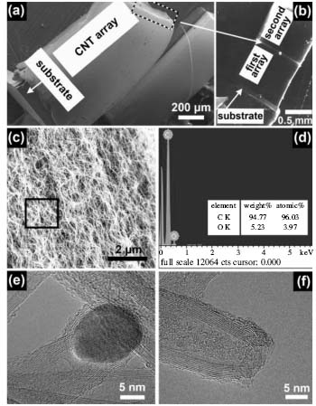
A small bundle of CNTs is taken from a CNT array with a tying forceps (MR-F211T-2, made of titanium by Suzhou Mingren Eye Instruments). The bottom end of the CNT bundle is fixed to a substrate (aluminum tape/silicon) with the other end free; thus an original CNT cantilever is obtained (Fig. 3(a)). When a magnet is moved toward the original CNT cantilever, the attraction and deflection of the cantilever can be clearly observed under an optical microscope (Fig. 3(b)). When the magnet is moved away, the CNT cantilever returns to its original position, indicating the elastic nature of this deformation. This process can be repeated very well and is clearly demonstrated by the video shown in the supporting information (video0). An interesting observation is that after the tip of an original CNT cantilever is cut off with scissors (MR-S221T, made of titanium by Suzhou Mingren Eye Instruments), the resulting shorter cantilever is still attracted by and deflected by the magnet. When the magnet is moved towards or away from the CNT cantilever, the deflection of the cantilever and its return to the original position are clearly observed (Figs. 3(c), 3(d) and video1 in the supporting information).
 | Fig. 3. (a) An original CNT cantilever and the cylindrical magnet nearby. (b) When the magnet is moved toward the CNT cantilever, the attraction and deflection of the cantilever can be clearly observed and measured. In the inset, the solid and dashed lines (not in scale) correspond to the cantilever in panels (b) and (a), respectively. (c) The cut-off CNT cantilever, which is obtained by cutting off the tip of the one shown in panel (a), and the cylindrical magnet nearby. (d) When the magnet is moved toward the CNT cantilever, the attraction and deflection of the CNT cantilever can be clearly observed and measured. In the inset, the solid and dashed lines (not in scale) correspond to the cantilever in panels (d) and (c), respectively. |
What are the origins of these interesting observations? First, the diamagnetic property of bulk graphite is not applicable, because bulk graphite is repelled by a permanent magnet. Second, possible electrostatic attractions between the CNT cantilever and the magnet (they carry charges of opposite sign) can be excluded because after the cantilever and the magnet are in contact with each other, the attraction can still be observed. Meanwhile, control experiments such as replacing the magnet is with a rod of copper, the attraction and deflection of CNT cantilever cannot be observed. Another reasonable explanation is that the attractive force indicates that there is magnetic moment at the CNT cantilever.[13]
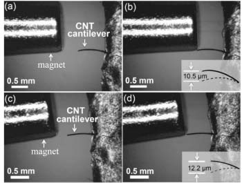
In order to find the point of application of force (the location of the magnetic moment), the following experiments were carried out: the magnet was moved along the “ y-axis” and the corresponding deflections of the CNT cantilever were measured as shown in Fig. 4. Shown here are the results for a cut-off cantilever, similar results were obtained for original cantilevers. “ y-axis” is parallel to the axis of CNTs at the tip of the CNT cantilever, and its origin is at the cross point between “ y-axis” and the central line of the cylindrical magnet when it passes through the tip of the cantilever. The deflections of the CNT cantilever have the maximum value at “ y = 0” (Figs. 4(a) and 4(d), where the gradient of the magnetic field produced by the cylindrical magnet has the largest value.[13] Meanwhile, deflections of the CNT cantilever are almost symmetrical on the “ y-axis” (Fig. 4(d), polynomial fit). Two special situations are shown in Figs. 4(b) and 4(c), where the absolute value of “ y” is equal to the radius of the cylindrical magnet. The symmetry of deflections on the “ y-axis” indicates that the attractive force is applied only at the tip of the CNT cantilever.
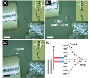 | Fig. 4. Symmetric deflections of a cut-off CNT cantilever along the y-axis, indicating that the point of application of force is at the tip of the cantilever. In the insets, the solid and dashed lines (not in scale) correspond to the positions of the cantilever in panels (a), (b), (c) and its original position, respectively. (a) At “ y = 0” , the deflection of the CNT cantilever has the maximum value. (b) and (c) When the magnet is moved to positions of “ y = 0.8 mm” (b) and “ y = – 0.8 mm” (c) (0.8 mm, radius of the cylindrical magnet), the deflection of the CNT cantilever has almost the same value. (d) Definitions of “ y-axis” (left) and the “ y-D” curve (right). The deflection of CNT cantilever is symmetric on the y-axis, indicating that the point of application of force is at the tip of the cantilever; therefore, the magnetic moment is at the open ends of the CNTs. |
The above results indicate that there is magnetic moment at the ends of CNTs either with open ends or with iron catalytic nanoparticles at the tips (Fig. 1). In the non-uniform magnetic field, there will be a force applied on the magnetic moment. This force can be decomposed into two component forces: one is parallel to and the other is perpendicular to the CNT cantilever. The latter force makes the CNT cantilever deflect and can be obtained by measuring the deflections; meanwhile, the former one is difficult to study since it tends to make the CNT cantilever shorter or longer, which is not observed under an optical microscope in this work. By measuring the deflections of these two kinds of cantilevers and comparing between them, the component forces (perpendicular to the cantilevers) can be obtained.
As a matter of fact, the magnitude of magnetic moment can be estimated from the following equations:[13, 14]

where D is the deflection, F⊥ is the component force at the tip (perpendicular to the cantilever), L is the length of the cantilever, E is the modulus of elasticity of the cantilever, I is the areal moment of inertia of the cantilever, F is the force at the tip of the cantilever, ∇ is the gradient operator, M is the magnetic moment, and H is the magnetic field strength.
Table 1 summarizes the experimental results for 24 CNT cantilevers, including 12 original CNT cantilevers and 12 cut-off cantilevers. In calculations of F0⊥ /F1⊥ and M0/M1, (F0⊥ , M0 and F1⊥ , M1 represent those of original and cut-off cantilevers, respectively), the following assumptions are used:
| Table 1. Properties of CNT cantilevers. L0 (length), D0 (deflection), F0⊥ (component force), and M0 (magnetic moment) represent those of original CNT cantilevers; L1, D1, F1⊥ , and M1 represent those of the corresponding cut-off CNT cantilevers. The average value of M0/M1 is 0.70. |
1) The modulus of elasticity (E) and areal moment of inertia (I) of a cut-off CNT cantilever have the same values as those of the corresponding original cantilever.
2) The magnetic moment at the tips of CNTs switches to the direction of the external magnetic field of the magnet. This assumption is justified by the observations that when north or south pole of the magnet is moved toward the cantilevers, only attraction and deflections of the cantilevers are found. The deflections have similar values.
As shown in Table 1, the ratios of magnetic moment M0/M1 are a little different from those of F0⊥ /F1⊥ , which are revised according to the direction and gradient of the magnetic field of the cylindrical magnet at the tip of CNT cantilevers. The average value of M0/M1 is 0.70, which means that the magnetic moment at the open ends of CNTs is larger than that at the tips of CNTs with iron catalytic nanoparticles. For a CNT with a catalytic nanoparticle at the tip (Figs. 2(e) and 2(f)), its magnetic moment at the tip can be regarded as the sum of the magnetic moment at the open end of the CNT (MCNT) and that of the iron nanoparticle (MFe). There are three possible situations for this sum: M0 = MCNT − MFe, M0 = MCNT + MFe, or M0 = MFe − MCNT. If we assume MCNT is equal to M1 (Figs. 2(e) and 2(f)), the situation of M0 = MCNT + MFe can be excluded from the ratio of M0/M1 (0.70). From the other two situations, the magnetic moment at the open end of the CNT (MCNT) can be obtained as 3.33 MFe and 0.59 MFe, respectively. From the present experimental results, it is difficult to prove which one is more reasonable. Both values are used in the following discussion and calculation of the magnetic moment at the open ends of CNTs.
The morphologies of iron catalytic nanoparticles at the tips of CNTs differ from one another, and their volume and number of atoms can be estimated according to TEM images (Table 2). Meanwhile, the area of cross section of the corresponding CNT can be obtained based on their inner and outer diameters. Since the sizes of catalytic iron nanoparticles at tips of CNTs are in the range about 20 ∼ 40 nm, each one can be regarded as a single magnetic domain and the magnetic moment can be obtained with: NFe · 2.16 μ B, where NFe is the number of iron atoms and μ B is Bohr magneton (at room temperature, each iron atom has a magnetic moment of 2.16 μ B). From the equation of MCNT = 0.59 MFe (or 3.33 MFe) the magnetic moment per unit area at the cross section of a CNT can be obtained, which is 4.73 μ B/Å 2 (or 26.7 μ B/Å 2). When the spacing of 3.4 Å between different graphite layers and ∼ 1 Å between edge carbon atoms are used, the magnetic moment of each edge carbon atom will be 16.1 μ B (or 90.1 μ B), which corresponds to a local magnetic induction of 19.0 T (or 107 T), [1] indicating great potential for applications. Meanwhile, we note that the experiments performed in this work are based on a bundle of CNTs, which is composed of huge number of nanotubes. While the model and calculation are based on an individual or limited number of nanotubes, this may result in some uncertainty in the final results.
| Table 2. The volume and number of iron atoms in 40 catalytic nanoparticles at the tips of CNTs and the area of cross section of corresponding CNTs. |
One important and interesting question is the origin and mechanism of this giant magnetic moment since the magnetic moment reported in this work is 2 ∼ 4 orders of magnitude higher than those reported previously.[1, 4] Although the exact mechanism is not clear, we propose that this giant magnetic moment is closely related to the spin- orbit coupling which results in end-state at the open ends of carbon nanotubes. The magnetic moment of spin origin is calculated with eħ /2m*, where m* is the effective mass of Bloch electrons, e is the charge of an electron, and ħ is the Planck constant. Meanwhile, we note that in graphene samples the effective mass of carrier is in the range of 0.02 ∼ 0.05me, [15– 18] and the corresponding local magnetic field can be as high as 24.0– 60.0 T, indicating great potential for applications.
4. Conclusion
In summary, by studying the deflections of CNT cantilevers near a permanent magnet, we have demonstrated that there is magnetic moment at the open ends of mutiwalled carbon nanotubes. By comparison of the deflection between original and corresponding cut-off cantilever, the magnitude and areal density of magnetic moment at open ends of CNTs are estimated. We have proposed and discussed the mechanism of this giant magnetic moment, which deserves more experimental and theoretical work. It should be noted that the curvature, confinement, and periodic condition along the circumference of CNTs seems to affect the magnitude of magnetic moment at open ends of CNTs compared to that at edges of graphenes samples, [19, 20] which would be more pronounced for CNTs with smaller diameters.[21, 22]
Reference
| 1 |
|
| 2 |
|
| 3 |
|
| 4 |
|
| 5 |
|
| 6 |
|
| 7 |
|
| 8 |
|
| 9 |
|
| 10 |
|
| 11 |
|
| 12 |
|
| 13 |
|
| 14 |
|
| 15 |
|
| 16 |
|
| 17 |
|
| 18 |
|
| 19 |
|
| 20 |
|
| 21 |
|
| 22 |
|