Aperture efficiency and mode constituent analysis for OAM vortex beam generated by digital metasurface
Air Force Engineering University, Xi’an 710077, China
† Corresponding author. E-mail:
xiangyucaokdy@163.com
1. IntroductionOrbital angular momentum (OAM) was discovered in light beams in 1992 for the first time.[1] Since then, OAM vortex beam has attracted tremendous interests.[2–7] At the very beginning, the research of OAM mainly focused on optics field. Until 2007, the concept of photon OAM was extended to microwave bands and a simulation was conducted to generate OAM vortex beam utilizing phased array antenna.[8] In 2012, an experiment successfully demonstrated that the OAM vortex beam can be utilized to increase wireless communication capacity,[9] which is an inspiring achievement for the scarce spectrum resource. Besides, the OAM vortex beam can also be applied to other fields such as radar pulse generation[10] and radar targets detection,[11] naming a few. Therefore, the research of OAM vortex beam in microwave bands is of great significance. The standard OAM generation approach includes spiral phase plate (SPP),[12] holographic plate,[13] circular traveling-wave antenna[14] and so on. Quite recently, a novel method was proposed to generate OAM vortex radio beams utilizing a reflective metasurface.[15] By carefully tailoring the reflection phase of each element constituting the metasurface, the helical phase profile related with eilφ can be obtained. Due to the powerful manipulation ability on electromagnetic waves, metasurface was widely applied to the generation of OAM vortex radio beams in the following researches.[16–21] Designing the elements that can provide 2π phase shift is the challenge for such metasurfaces. In fact, a more concise device called digital metasurface has been applied to antenna designs since the concept was proposed in 2014.[22] The elements of n-bit digital metasurface have 2n discrete reflection/transmission phase states[23] and do not need to cover the whole 2π phase range. These elements can be coded into different sequences to obtain different desired functions.[24] Moreover, the reconfigurable designs for reflectarray antennas can also be realized by using digital metasurface.[25] In the previous research, we have successfully introduced the digital metasurface into the generation of OAM vortex beam.[26] Nevertheless, there still exist two important issues which are worthy of being studied. One is the aperture efficiency, which is a non-ignorable index in metasurface applications especially for digital metasurface devices. The other one is the mode constituent of the OAM vortex beam, which directly indicates the mode purity of the generated OAM vortex beam.
In this paper, the quantitative analysis of the aperture efficiency and mode constituent for OAM vortex beam generated by digital metasurface is carried out. The mathematical modeling for OAM vortex beam generation is presented first. Afterwards, the numerical computation based on the mathematical model is conducted for different bit numbers and topological charges. Then, a 1-bit metasurface is simulated, fabricated and experimentally measured to demonstrate the numerical computation. In the end, conclusions are drawn to summarize the work of this paper.
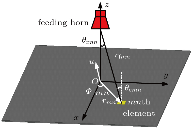
2. Mathematical modelingConsider a metasurface composed of M × N elements. It is illuminated by the incident wave irradiated from a feeding horn antenna, which is located above the center of the metasurface as shown in Fig. 1. The reflected wave is given by[27]
where
Here, cos
qeθ is the element pattern in transmission mode and
qe is 1 unless otherwise specified.
krfmn is the phase introduced by the different incident path.
φmn and
rmn are the compensated phase and position vector of the
mnth element, respectively.
u is the unit vector of arbitrary direction. cos
qfθfmn is the feeding pattern of the horn antenna and cos
qeθemn is the element pattern in receiving mode.
qf is set to be 6.5 to simulate the radiation pattern of the feeding horn. |
Γmn| represents the reflection magnitude of the
mnth element and is assumed to be 1.
k is the wavenumber in vacuum. The angles, vectors, and distances are depicted in Fig.
1. In order to generate OAM vortex beam in
u direction, the compensated phase
φmn is supposed to satisfy
with
l being the topological charge of OAM and
Φmn the azimuthal angle of the
mnth element.
Figure 2(a) gives the distribution map of φmn at 6 GHz for generation of OAM vortex beam in normal direction. Note that the element size is 15 mm × 15 mm and the scale of the metasurface is 30 × 30. Besides, the distance between the feeding horn antenna and the reflective metasurface is 400 mm. The normalized radiation pattern and phase distribution in uv plane (u = sin θ cos φ, v = sin θ sin φ) are respectively shown in Figs. 2(b) and 2(c). The doughnut-like main lobe and phase related with azimuthal angle can be clearly observed, indicating that OAM vortex beam is successfully generated.
Phase quantization is the main characteristic of digital metasurface. For n-bit (n = 1, 2, 3, …) phase quantization, the compensated phase φmn|n-bit is given by
Figures
3(a),
3(b), and
3(c) are the 1-bit, 2-bit, and 3-bit compensated phase transformed from the continuous phase
φmn shown in Fig.
2(a), respectively. The corresponding radiation patterns and phase distributions in the
uv plane are depicted in Figs.
3(d)–
3(i). It is seen that OAM vortex beams are all successfully generated by 1-bit, 2-bit, and 3-bit digital metasurface.
3. Aperture efficiency and mode constituent analysisDue to the existence of phase quantization error,[23] the radiation performance of digital reflectarray antennas are worsened at different levels, which can be seen from Figs. 3(d), 3(e), and 3(f). Thus, it is of high necessity to analyze the aperture efficiency and mode constituent for OAM vortex beam.
Table 1.
Table 1.
 Table 1. Gain and aperture efficiency for different metasurfaces. .
| Metasurface |
Peak gain/dB |
Aperture efficiency |
| Continuous |
21.7 |
14.6% |
| 1-bit |
19.4 |
8.5% |
| 2-bit |
21.5 |
14.0% |
| 3-bit |
21.6 |
14.5% |
| Ref. [28] |
19.9(X band), 18.8(C band) |
7.1%(X band), 13.8%(C band) |
| Ref. [29] |
21.5 |
12.09% |
| Table 1. Gain and aperture efficiency for different metasurfaces. . |
The gain value versus θ in φ = 0 plane is shown in Fig. 4(a). Obvious gain loss and strengthened side lobes can be observed for 1-bit pattern compared with the continuous one, which is caused by the large quantization error. While for 2-bit and 3-bit metasurfaces, the quantization error is much smaller than 1-bit design so that the corresponding radiation patterns agree well with that of the continuous one. Table 1 lists the peak gain values in full space and the aperture efficiency η given by
where
G is the peak gain,
A represents the aperture size of the metasurface, and
λ denotes the working wavelength in free space. It is seen in Table
1 that the peak gain of 1-bit metasurface is 2.3 dB lower than that of the continuous one, making the aperture efficiency drop from 14.6% to 8.5%. For 2-bit and 3-bit metasurface, the gain loss is rather small and the aperture efficiency is quite close to the continuous one. It is worth mentioning that the aperture efficiency of the proposed metasurface is comparable with other works.
[28,29]The OAM spectrum is the complex Fourier transform of the OAM vortex beam. Their numerical relationship is given by[30]
where
ψ(
φ) is the phase value extracted along the sampling circle centered on the beam axis. In this paper, a circle containing the maximum field (black circles in Fig.
3) is chosen as the sampling circle. It is worth mentioning that the bit number does not affect the size of the sampling circle because it has no relationship with the divergence angle of the OAM vortex beam.
[31] Figure
4(b) gives the OAM spectrum of the vortex beams with topological charge
l = 1 generated by different metasurfaces.
ψ(
φ) is extracted at
θ = 5°. It is seen that the OAM mode with
l = 1 is dominant for all metasurfaces as expected. The parasitic modes with
l = −3 and
l = 5 are also observed, but they are extremely small. Especially, for 1-bit metasurface, the parasitic modes are also stimulated at
l = −1 and
l = 3. Nevertheless, these parasitic modes are still small enough to be neglected. Thus, a meaningful conclusion can be drawn that high purity OAM vortex beam can be generated by digital metasurface, including the 1-bit device which has the largest quantization error.
For a fixed metasurface, the radiation performance of OAM vortex beam is closely related with topological charge l. Figures 5(a) and 5(b) depict the radiation patterns in φ = 0 plane of OAM vortex beam with l = 3 and l = 5. It is apparent that the gain is sharply reduced compared with that of l = 1. Besides, the enlarged divergence angle and enhanced side lobes are also observed. Table 2 lists the corresponding peak gain values in full space and aperture efficiency for l = 3 and l = 5, respectively. With the increase of l, the radiation performance deteriorates rapidly. For l = 5, the maximum gain drops to 14.7 dB and the aperture efficiency falls to 2.9% for the continuous metasurface. These two indexes are even lower for 1-bit metasurface. This phenomenon indicates that for a fixed metasurface, overlarge topological charge l is inadvisable in practical applications.
Table 2.
Table 2.
 Table 2. Gain and aperture efficiency for l = 3 and l = 5. .
| Metasurface |
Peak gain/dB |
Aperture efficiency |
| l = 3 |
l = 5 |
l = 3 |
l = 5 |
| Continuous |
17.1 |
14.7 |
5% |
2.9% |
| 1-bit |
14.8 |
12.3 |
2.9% |
1.7% |
| 2-bit |
17.0 |
14.5 |
4.9% |
2.8% |
| 3-bit |
17.1 |
14.7 |
5% |
2.9% |
| Table 2. Gain and aperture efficiency for l = 3 and l = 5. . |
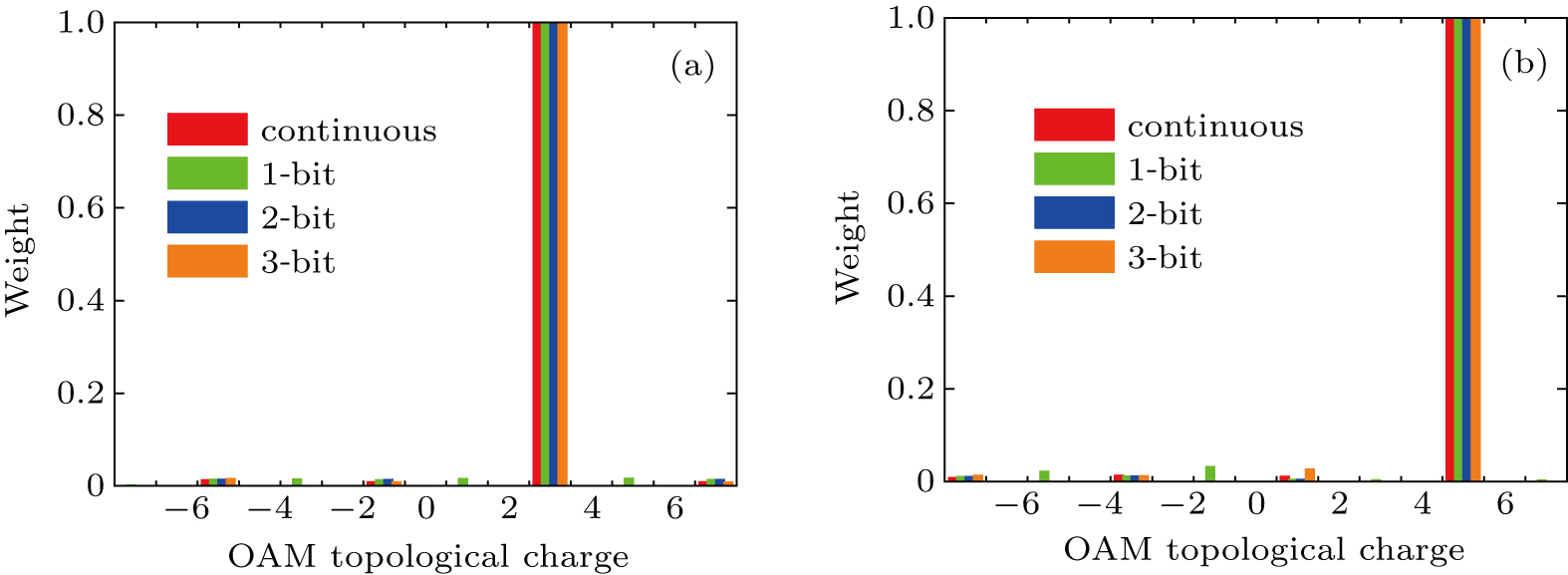
Next, the OAM mode constituent is discussed. Figure 6 shows the spectrum of OAM vortex beam with l = 3 and l = 5. ψ(φ) is extracted at θ = 11° for l = 3 and θ = 14° for l = 5, both denoting the direction of maximum radiation. Different from the deterioration of radiation pattern, the designated mode is still dominant in the domain of main lobe. The other parasitic modes can also be neglected. Nevertheless, a parasitic beam, which is very similar to OAM vortex beam, is observed between the two radiation peaks of the main lobe for l = 5 shown in Fig. 5(b). It is quite necessary to analyze the constituent of this parasitic beam. Thus, ψ(φ) is extracted at θ = 3° (the peak direction of the parasitic beam) to compute the spectrum, which is shown in Fig. 7. A dominant mode of l = 1 is observed for all the metasurfaces. Besides, the other modes of l = −3 and l = 5 are also seen but are quite small. Specially, two other larger parasitic modes occur at l = −1 and l = 3 for 1-bit metasurface, which is in good agreement with that of the designated l = 1 vortex beam shown in Fig. 4(b). The OAM spectrum manifests that the parasitic beam is indeed the OAM vortex beam. This vortex beam may be generated when the designated main mode l is overlarge. To eliminate the parasitic beam, we can enlarge the scale of the metasurface.
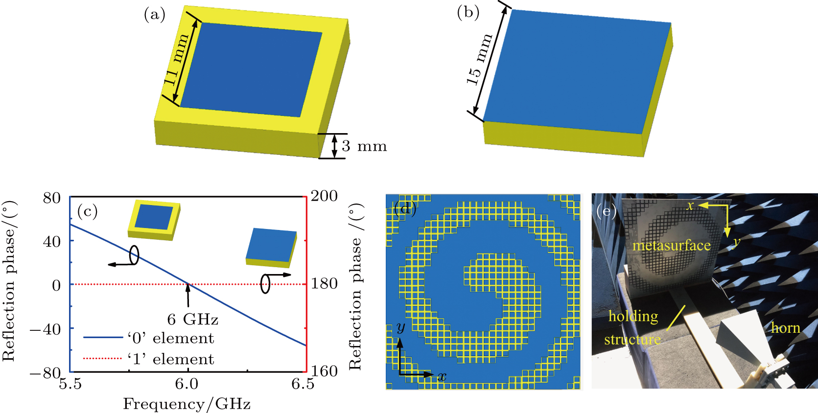
4. Prototype testTo verify the computations, a prototype of the 1-bit metasurface was simulated, fabricated and measured in anechoic chamber. Note that the topological charge of the generated OAM vortex beam was l = 1. The metasurface is composed of two kinds of elements as shown in Figs. 8(a) and 8(b). These elements were metallic patches etched on substrate (εr = 2.65) with a metallic ground. The thickness of the substrate is 3 mm. Figure 8(c) depicts the simulated reflection phase of the elements versus frequency. The simulation was conducted using commercial software HFSS. It is seen that the reflection phase difference of the two kinds of elements is π at 6 GHz, satisfying the condition of 1-bit phase quantization. According to the compensated phase distribution shown in Fig. 3(a), the 1-bit metasurface is configured as shown in Fig. 8(d). By using PCB (Printed Circuit Board) technology, a prototype was fabricated and measured in anechoic chamber. A standard horn working at 6 GHz was used as the feeding antenna as shown in Fig. 8(e). A tailor-made structure was employed to hold the metasurface and the feeding horn. In the experiment, vertical polarization was employed. It is worth mentioning that horizontal polarization is also effective since the reflection phase of the elements keeps the same under both polarizations.
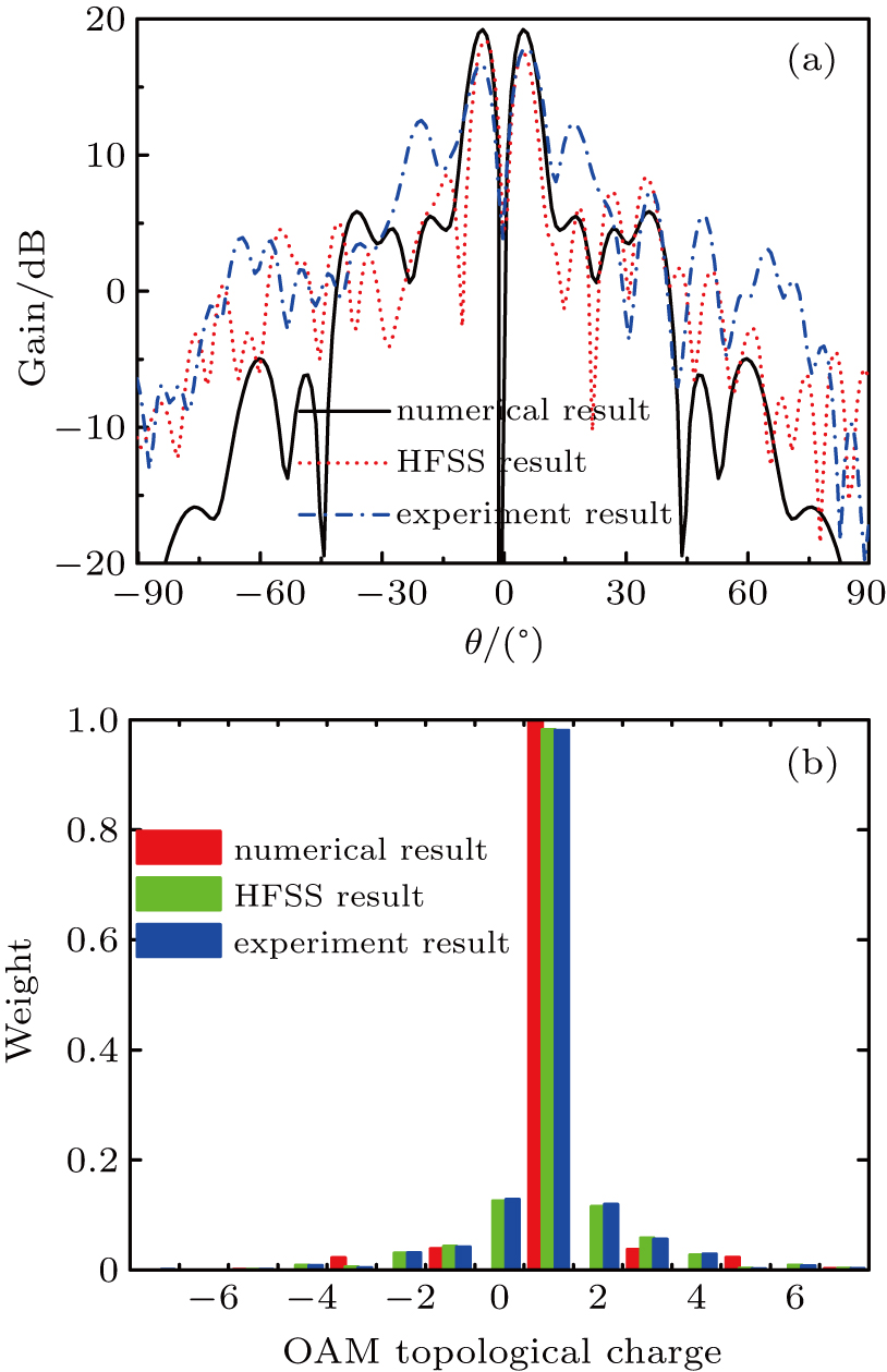
The radiation phase distribution on observation plane was measured and shown in Fig. 9. For contrast, the simulated result is also depicted. The observation plane with the size of 1000 mm × 1000 mm is parallel to the metasurface aperture and the distance between them is 3 m. It is seen that the helical phase front was obtained. The measured result agrees well with the simulated one. The radiation patterns and OAM mode spectrum obtained through numerical computation, HFSS simulation and experiment test are depicted in Fig. 10(a). The measured side lobes are higher than that of the numerical and HFSS result, which is due to the fabrication error and measurement error. In general, however, the measurement result agrees well with the other two. Table 3 lists the comparison of the corresponding gain and efficiency. It is observed that the gains of HFSS and experiment results are approximately 1 dB and 2.2 dB lower than the numerical one, respectively, making the aperture efficiency decrease by about 1.7% and 3.3%. This reduction is mainly attributed to the blockage effect of the feeding horn, which does not exist in numerical computation. On the other hand, according to the OAM spectrum shown in Fig. 10(b), it is found that the l = 1 mode of the HFSS and experiment results is slightly lower than numerical one, but is still dominant. The other parasitic modes are much smaller. Generally, the HFSS and experiment results agree well with the numerical computations, verifying the correctness of the analysis.
Table 3.
Table 3.
 Table 3. Comparison of gain and aperture efficiency for 1-bit metasurface. .
| Metasurface |
Peak gain/dB |
Aperture efficiency |
| Numerical |
19.4 |
8.5% |
| HFSS |
18.4 |
6.8% |
| Experiment |
17.2 |
5.2% |
| Table 3. Comparison of gain and aperture efficiency for 1-bit metasurface. . |
5. ConclusionIn summary, the aperture efficiency and mode constituent of OAM vortex beam generated by digital metasurface is comprehensively investigated. The phase quantization error of digital metasurface results in the loss of gain and aperture efficiency, which is quantitatively analyzed for different bit numbers. Fortunately, it is found that the OAM spectrum is barely affected by phase quantization, indicating that high purity OAM vortex beam can be generated by digital metasurface. Besides, the influence of topological charge l is also studied. It is observed that the growing of l will deteriorate the radiation performance of OAM vortex beam significantly and will stimulate dominant parasitic OAM modes at certain angle. Finally, the simulation and experiment of a 1-bit metasurface prototype demonstrate the numerical computations.


