Project supported by the National Key Research and Development Program of China (Grant Nos. 2016YFB0501600 and 2017YFB0503100) and the National Natural Science Foundation of China (Grant Nos. 61773043, 61673041, and 61721091).
Project supported by the National Key Research and Development Program of China (Grant Nos. 2016YFB0501600 and 2017YFB0503100) and the National Natural Science Foundation of China (Grant Nos. 61773043, 61673041, and 61721091).
† Corresponding author. E-mail:
Project supported by the National Key Research and Development Program of China (Grant Nos. 2016YFB0501600 and 2017YFB0503100) and the National Natural Science Foundation of China (Grant Nos. 61773043, 61673041, and 61721091).
A nuclear spin gyroscope based on an alkali-metal–noble-gas co-magnetometer operated in spin-exchange relaxation-free (SERF) regime is a promising atomic rotation sensor for its ultra-high fundamental sensitivity. However, the fluctuation of probe light intensity is one of the main technical error sources that limits the bias stability of the gyroscope. Here we propose a novel method to suppress the bias error induced by probe light intensity fluctuations. This method is based on the inherent magnetic field response characteristics of the gyroscope. By the application of a bias magnetic field, the gyroscope can be tuned to a working point where the output signal is insensitive to probe light intensity variation, referred to herein as ‘zero point’, thus the bias error induced by intensity fluctuations can be completely suppressed. The superiority of the method was verified on a K–Rb–21Ne co-magnetometer, and a bias stability of approximately 0.01 °/h was obtained. In addition, the method proposed here can remove the requirement of the closed-loop control of probe light intensity, thereby facilitating miniaturization of the gyroscope volume and improvement of reliability.
High-precision gyroscopes have found wide applications in inertial navigation, geophysics studies, fundamental physics, and so on.[1,2] Among these applications, one of the factors determining system performance and experimental results is the bias stability of the gyroscope. While the accuracy of the traditional gyroscopes based on classical mechanics or Sagnac effect of photons has reached a high level,[3,4] the research on gyroscopes based on new mechanism is still in progress. As quantum sensing technology becomes a distinct field of research,[5] gyroscopes based on the fascinating property of ultrahigh sensitivity of atomic sensors have been developed, including atomic interferometer gyroscopes[6,7] and nuclear spin gyroscopes.[8,9] Nuclear spin gyroscopes have attracted a lot of research interest because of their high precision potential, easy integration, and insensitivity to vibration and gravity.[10] As the relaxation of coherent evolution qubits in a quantum system is a main factor that limits its performance, atomic magnetometers operated in spin-exchange relaxation-free (SERF) regime, where the relaxation of electron spins due to spin-exchange collisions is greatly suppressed, have become one of the most sensitive magnetometers to date.[11] Based on the ultrahigh magnetic sensitivity of SERF magnetometers, the Romalis group at Princeton University first proposed a novel type of nuclear spin gyroscope based on an alkali–metal–noble–gas co-magnetometer scheme in 2005, and a bias stability of 0.04 °/h was achieved on their K–3He co-magnetometer.[12] This type of gyroscope is usually called spin-exchange relaxation-free gyroscope (SERFG) and it features ultrahigh rotation sensing sensitivity and magnetic field disturbance cancellation ability. After that, the principles and theories of the gyroscope have been intensively studied and verified. Our group demonstrated a dual-axis SERFG with parametrical modulation technique, and a bias stability of better than 0.05 °/h was achieved in 2018.[13] After that, it was found that magnetic field fluctuations can still cause bias drift in SERFG.[14] By the analysis of the magnetic field response of this gyroscope, the bias error induced by magnetic noise has been suppressed to 5 × 10− 4 °/h.[15,16]
A SERFG usually utilizes an orthogonal pump-probe scheme.[17] A circularly polarized pump beam is used to pump the alkali–metal atoms, and a linearly polarized probe beam propagating along the direction perpendicular to the pump beam is used to detect the precession of atomic spin. The optical rotation of the probe beam is usually measured with a balanced photodetector[13] or polarization modulation technique.[18] As the scale factor of a SERFG is proportional to the light intensity of the probe beam, the light intensity fluctuations can couple into the output signal and induce bias drift. Therefore, light intensity stabilization system is usually used to suppress the fluctuations.[18] However, due to the temperature-dependent performance of optical components in the light intensity stabilization system (LISS), the intensity stabilization accuracy is greatly affected by the environment temperature variation.[19] In this letter, we propose a novel method to suppress the bias error induced by probe light intensity fluctuations. Based on the magnetic field response characteristic of SERFG,[15] a bias magnetic field is used to tune the system to the working point where the output signal is no longer sensitive to the probe light intensity variations. The superiority of our method was verified on a K–Rb–21Ne co-magnetometer, and a bias stability of approximately 0.01 °/h was achieved.
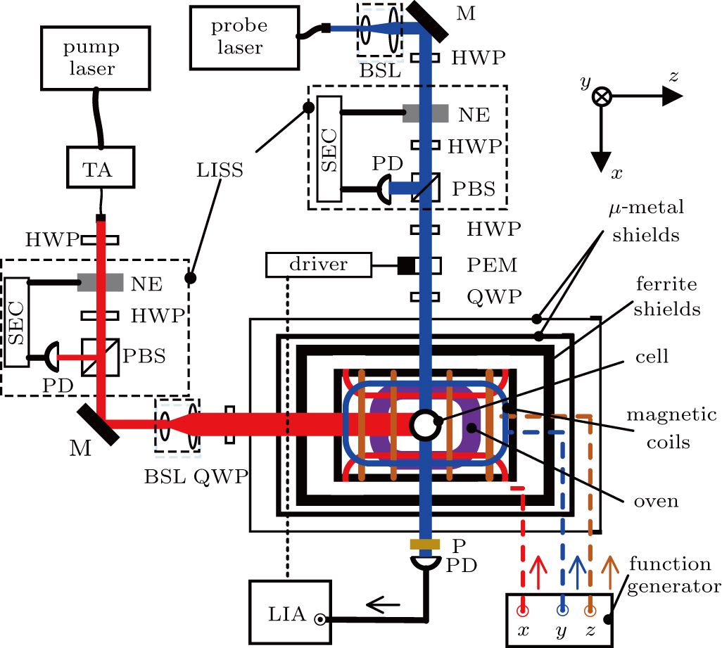
The schematic diagram of a SERFG is similar to that in our previous literature,[16] and is depicted in Fig.
A set of coupled Bloch equations are usually used to characterize the dynamics of the electron and nuclear spins in a SERFG. According to the theoretical and experimental results of the magnetic field transfer function analysis of SERFG,[15] the system can be described with a linear time-invariant system. When the polarization of atoms has reached equilibrium, an external compensation field Bc = −Bn −Be is employed along z axis to cancel the magnetic field from nuclear magnetization Bn and that from electron magnetization Be. If we take the transverse rotation rate Ωxi and Ωyi, the transverse magnetic field Bxi and Byi as system inputs, the leading steady state response terms of the gyroscope can be expressed as[18]


The compensation point is usually found based on Eq. (
The basic idea of our method to suppress the error induced by probe light intensity fluctuations consists in employing a bias Bx field to tune the gyroscope to the working point where the steady state offset is zero, herein is called the ‘zero point’. At zero point, the total optical rotation angle (θc + θr) in Eq. (
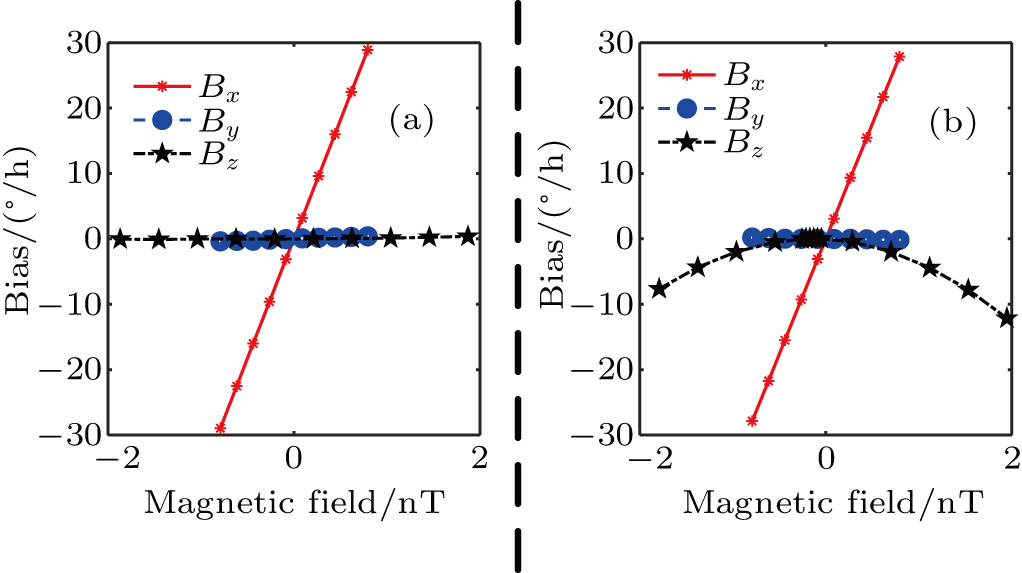
As mentioned above, the equivalent scale factor of the probe light intensity can be tuned by Bx field, as is shown in Fig.
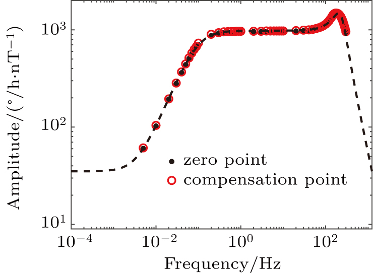
To illustrate that our method does not introduce other errors, the scale factors and magnetic field sensitivities of the SERFG at compensation point and zero point were also compared. The scale factor are calibrated with low frequency modulation of Bx field[23] and the results are shown in Fig.
 | Fig. 3. Amplitude frequency response to Bx field. It can be seen that the amplitude responses of the SERFG at zero point and compensation point share the same fitting line,[15] meaning that the scale factors to angular rate are identical. |
Another concern is the amplitudes of magnetic field response along three axes. When the gyroscope is working at zero point, the leading terms without steady state offset in Eq. (


The long term stability of the SERFG is evaluated by Allan deviation analysis and is shown in Fig.
In conclusion, we have developed a low drift nuclear spin gyroscope based on a K–Rb–21Ne co-magnetometer. Based on the magnetic field response characteristic, the working point of the gyroscope is tuned by Bx field from the compensation point to zero point where bias error induced by probe light intensity fluctuations can be completely suppressed, and no other errors are introduced. A bias stability of approximately 0.01 °/h is achieved. The method can remove the requirement of the closed-loop control of probe light intensity, thereby facilitating miniaturization of the gyroscope volume and improvement of reliability. In the future, we will devote to the suppression of the error induced by pump intensity fluctuations, to the suppression of magnetic field drift and to the closed-loop control of the zero point.
| [1] | |
| [2] | |
| [3] | |
| [4] | |
| [5] | |
| [6] | |
| [7] | |
| [8] | |
| [9] | |
| [10] | |
| [11] | |
| [12] | |
| [13] | |
| [14] | |
| [15] | |
| [16] | |
| [17] | |
| [18] | |
| [19] | |
| [20] | |
| [21] | |
| [22] | |
| [23] |


