Low drift nuclear spin gyroscope with probe light intensity error suppression
Project supported by the National Key Research and Development Program of China (Grant Nos. 2016YFB0501600 and 2017YFB0503100) and the National Natural Science Foundation of China (Grant Nos. 61773043, 61673041, and 61721091).
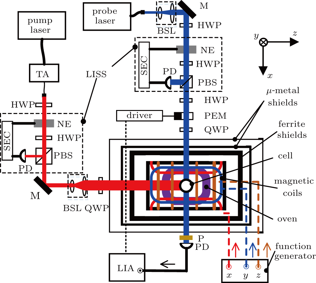
Schematic diagram of the SERFG. TA: tapered amplifier, BSL: beam shaping lenses; M: reflection mirror; P: linear polarizer; NE: noise eater; HWP: half wave plate; PBS: polarizing beam splitter; QWP: quarter wave plate; PD: photodiode; PEM: photo-elastic modulator; LIA: lock-in amplifier; SEC: servo electronic circuit. An LISS mainly compromises of an NE, an HWP, a PBS, a PD, and an SEC. The output laser intensity of the LISS is monitored by the PD, which detects the intensity of a small portion of laser split by the PBS. The PD signal is fed into the SEC. The SEC compares the current laser intensity with the set-point value and changes the driving voltage applied to the NE to change the output laser intensity.
