1. IntroductionIn the past decade, the increasing interest has been aroused in the use of hybrid optical and digital techniques to provide improved imaging capabilities or extra degrees of freedom in designing the imaging systems. This technique which is known as wavefront coding brought great changes to optical system design.[1–3] The wavefront coding system consists of two parts: optical encoding and digital decoding. The system is optically encoded by using a specially designed phase mask on the pupil plane, thus it has particular characteristics such as sensitivity to the object distance.[4] The images captured in the image plane are called encoded images. Desired information such as object distance or sharp graphics information is usually extracted from the encoded images through digital decoding.
Simonov et al. presented a single-image passive ranging and three-dimensional (3D) imaging system in incoherent light based on a wavefront coding technology by using a chiral phase mask in 2011.[4] They analyzed the system in the frequency domain, while in the present paper we present the theoretical analysis in the spatial domain. We deduct the analytic relationships between the object distance and the point spread function, and between the object distance and the encoded image. Then the depth information can be extracted from the encoded images. In addition, the chiral phase mask used in previous research is processed by machine tools. Since the optimal parameter of the phase mask may vary with service time and circumstances, it is beneficial to employ a programmable phase element that can be optimized in real time.[5] Therefore, the phase mask is generated by a spatial light modulator (SLM), which is an object that imposes some form of spatially varying modulation on a light beam and it is programmable in real time. By doing this, we set up a programmable real-time passive ranging system. It is more flexible and can be adjusted in real time.
In Section 2 the theoretical analysis of the passive ranging system through chiral phase encoding is carried out. The object distance is very sensitive to the point spread function (PSF) of the wavefront coding system. The analytic relationships are demonstrated between the object distance and the PSF, and between the object distance and the encoded images. Experimental analysis is given in Section 3. First, the SLM is calibrated to obtain the optimal phase modulation for optical encoding in the wavefront coding system. Then a doublet is used as an example to set up the system and an SLM is used as the phase mask. Finally, the depth map is extracted from the encoded image successfully. Section 4 is devoted to the discussion and conclusion.
2. Theoretical analysisThe imaging quality of an optical system is determined by the pupil function.[6,7] By adding a chiral phase mask on the pupil plane, the optical system becomes particularly sensitive to the object distance. The object distance reflects the depth information in the object space. The digital decoding is used to extract the depth map from the encoded image. The depth information can be used to restore the 3D image of the object. This paper will analyze the system in the space domain.
2.1. Optical encodingSharp images will be achieved if the system satisfies the Gauss imaging formula. Assume that f is the focal length of the optical system, zi is the image distance, and zo is the object distance. Similarly, the image distance will change
 to obtain sharp images when the object distance varies
 . Both of them satisfy the Gaussian lens formula[8,9]
Therefore, the variation of the object distance leads to the blurred image if
zi is kept unchanged. The aberration is called defocus aberration
φ and it is defined as
[10]where
D is the side length of a square pupil, and
λ is the incident light wavelength. For simplicity, all the aberrations are ignored except defocus aberration in this paper.
[2,11]It is assumed that a phase mask Z is placed on the pupil plane of the optical system. Then the exit pupil of an optical system can be described in canonical pupil coordinates
 as[12]
where

and

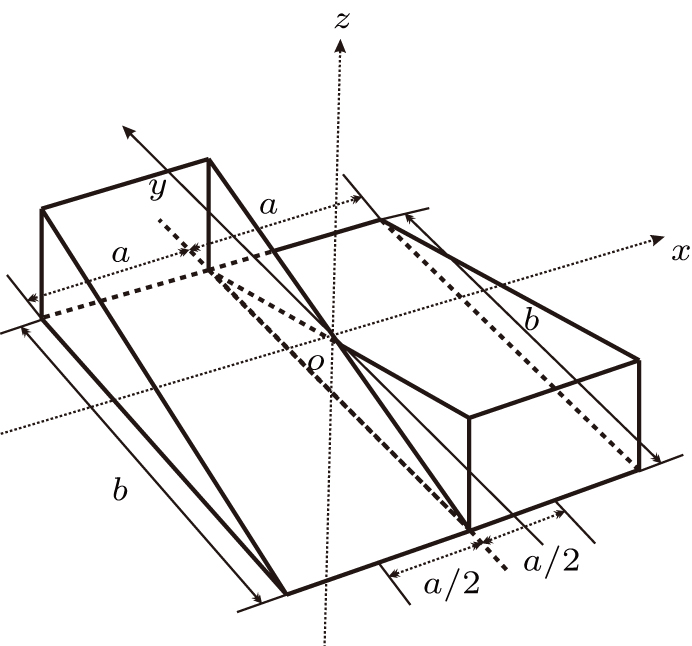
is the expression of the phase mask added to the pupil. Taking a chiral phase mask for example, it consists of two tilted planes with the opposite tilt constants, as shown in Fig.
1. Then we have
B is the prism constant, and
a and
b denote the width and length of a single inclined plane, respectively, as shown in Fig.
1.
The PSF of a wavefront coding optical system using a chiral phase mask is called the encoded PSF. In the case of small φ, it can be approximated as
where

represent the coordinates on the image plane,
M and
N are deduced in Appendix
A,
n is the refractive index of the phase mask, and
C0 is a function of defocused spot.
[10]According to Eq. (6), the encoded PSF consists of two defocused spots, which correspond to the two parts of the chiral phase mask shown in Fig. 1, respectively. The centers of the spots are located at
 and
and
 , respectively. The slope k of the line between the centers of the spots is calculated by (please refer to Appendix A)
In this way, the object distance can be calculated by measuring the slope of the line between the centers of the defocused spots in the PSF by using Eqs. (
1) and (
7).
However, the image captured in the image plane is regarded as the convolution of the object and PSF. Consequently, in the case of a spatially-extended object, to determine the unknown object distance, the encoded image should be additionally analyzed. We will discuss a method to extract the object distance from the encoded images in the following subsection.
2.2. Digital decodingSuppose that I denotes the object. Image
 , which is captured in the image plane, can be indicated as the convolution of the object and the PSF of the optical system. Using Eq. (6), the image
 is described as
where

indicates the convolution. Equation (
8) indicates that the encoded image is the superimposition of two parts which are described as

with two center-displacements

and

, respectively.
Note that the displacement in space domain corresponds to the phase shift in the frequency domain. Thus the spectrum of the object U0 in the frequency domain is the Fourier transform of the object

Let
, and its frequency domain

will be represented as
Note that
is the image of
with the displacement

in the

and

directions, respectively. According to the displacement theorem of the two-dimensional (2D) Fourier transform, its spectrum can be written as
where

denotes the coordinates in the frequency domain. Similarly, we obtain
According to Eqs. (
8), (
11), and (
12), the spectrum

of the image

is shown as follows:
Take the modulus of Eq. (
13),
The inverse Fourier transform is applied to Eq. (
14), which is represented by

. Considering that it is a complex function, thus taking the real part of

, we obtain
Generally, the low-frequency information is a dominant component of the object in the frequency domain. Therefore, there is a peak of

located at the zero frequency. Note that
and
are Dirac delta functions centered at

and

, respectively. According to the sampling property of the Dirac delta function,

can be regarded as

shifting

along the

axis and

along the

axis. Consequently, the peak of
is located at

. Similarly, the peak of

is located at
. In this way,

has two peaks located at
and

respectively, which are origin-symmetric. We call them the twin peaks. The slope of the line between the twin peaks of

is
k, which is the same as the slope of the line between the defocused spots of the PSF as shown in Eq. (
7). Thus, the object distance can be calculated through Eq. (
7).
Using this method, we can extract the depth information from the encoded images in the wavefront coding optical system with a chiral phase mask.
3. Experimental analysis3.1. Calibration of SLMAn SLM is used to generate the chiral phase instead of a machine-tooled phase mask for its flexibility. The SLM used here is a twisted-nematic liquid-crystal modulator (HEO0017) from Holoeye. The device enables electrically modulated birefringence in transmission mode and is controlled by means of a video signal with a resolution 1024×768 pixels and 8 bits in depth.
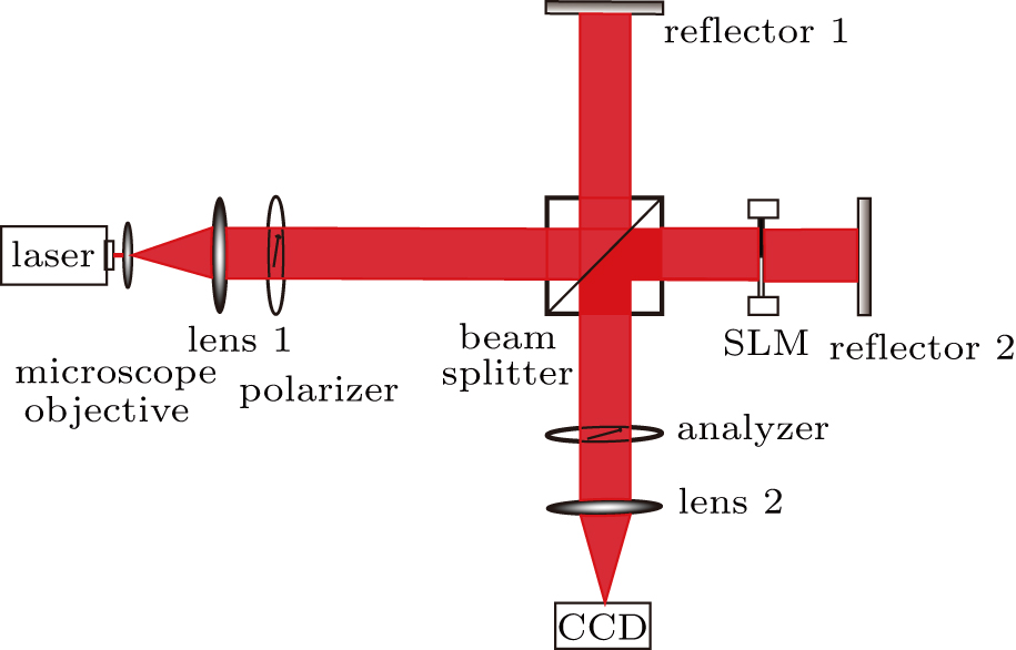
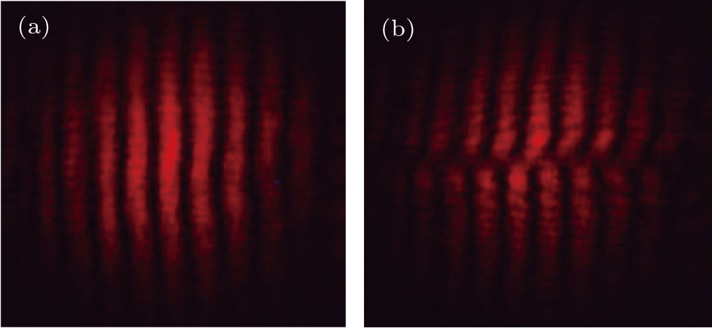
Generally, the SLM needs to be calibrated before use. An interference device is set up to calibrate the SLM. The SLM is placed between a polarizer and an analyzer. As shown in Fig. 2, light emitted from He–Ne laser is expanded by a microscope objective and lens 1. The light is divided into two beams by a beam splitter. One beam is reflected by the beam splitter and reflector 1, while the other beam goes through the beam splitter and is reflected by reflector 2. Both of the beams pass through lens 2 and focus on the image plane causing interference. The interference fringes are recorded by a charge coupled device (CCD) image sensor. As shown in Fig. 3(a), the fringes are straight if the modulations at all parts of the SLM in the application are at the same gray level, such as zero. However, there will be misplacement in fringe if the modulation at half of the SLM in the application of the gray level is 0, while the other half is 255 as shown in Fig. 3(b).
To achieve a maximum phase modulation, the optimal combination of angles of the polarizer and the analyzer need to be found out. The angles of the polarizer and analyzer are adjusted by keeping the modulation at half of the SLM in the application of the gray level at 0, while at another half of the SLM the gray level is at 255. The best combination of angles of the polarizer and the analyzer is obtained when the misplacement of interference fringes reaches the maximum.
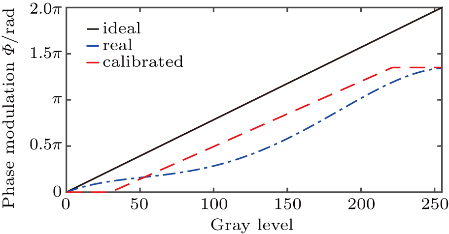
To obtain the relationship between the gray level and the phase modulation at the optimal combination of angles of the polarizer and the analyzer, the gray level of one half part of the SLM is kept at 0, and another half is linearly varied. The dynamic range for the variation of gray level is [0, 255]. The phase modulation caused by the variation of SLM gray level results in the misplacement of interference fringes. By measuring the misplacement of the interference fringe in the CCD, we obtain the phase modulation
where
ϕ is the phase modulation,

is the misplacement of the interference fringe, and
ϑ is the period width of the interference fringe. Thus, the relationship between the phase modulation
ϕ and the gray level is illustrated by the dash-dotted line in Fig.
4.
However, the ideal modulation curve is linear and ranges from 0 to 255 as shown by the solid line in Fig. 4. Neither the phase modulation nor the gray level of the SLM shows a linear relation. Thus there will be a phase modulation error. In order to overcome this deficiency, the SLM is calibrated by a look-up table with linear interpolation as shown by the dashed line in Fig. 4 to obtain the appropriate optimal phase modulation.
3.2. An example of wavefront coding systems through chiral phase encodingTo verify the rotation effect of the PSF, a PSF test system is set up as shown in Fig. 5. An achromatic lens is used as the imaging system. The focal length f of the lens is 200 mm. The image distance of the optical system zi is 250 mm. The object, a point light source, is generated by the He–Ne laser and a microscope objective on the translation stage. The point light source is 1000 mm away from the lens, i.e., the object distance zo is 1000 mm. The parameters of the chiral phase mask used in the experiment are described as those in Eq. (5), where
 , a = D/2, and b = D.
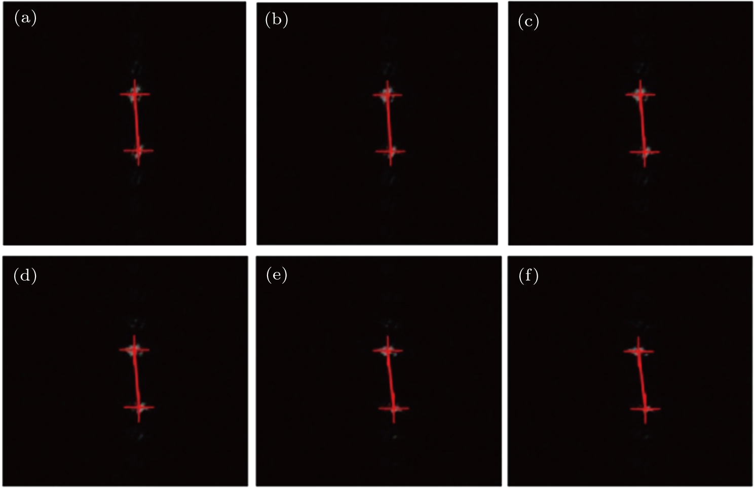
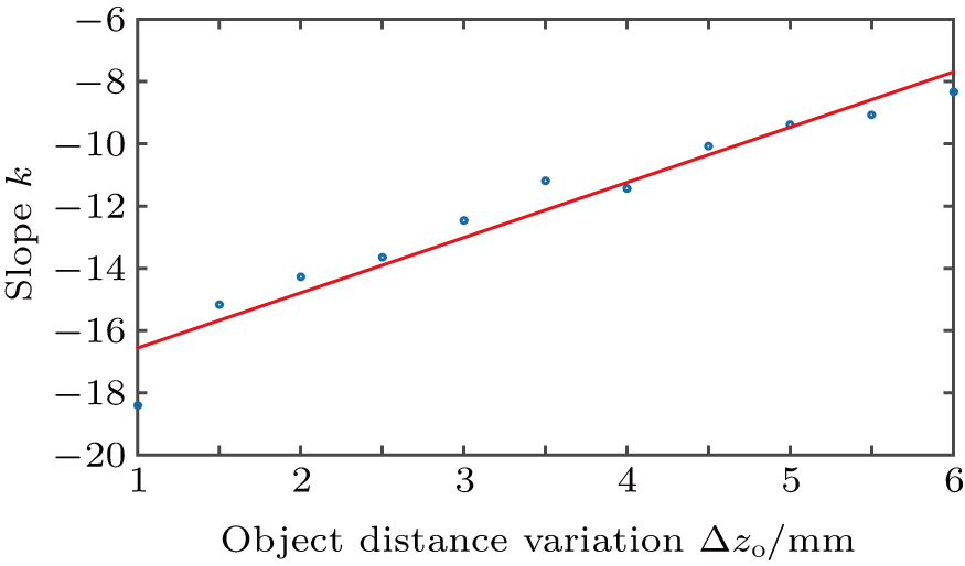
The object distance is varied by moving the microscope objective. Figure 6 shows the PSFs of different variations of the object distance
 . There are two spots in the PSF, and they rotate with the variation of the object distance. It is consistent with Eq. (6). The dots in Fig. 7 describe the slopes of the line between spots in PSF with different object distance variations. A linear fitting method is used to obtain the approximate relationship between the object distance variation and the slope as indicated by the solid line in Fig. 7. In this way, the connection between the object distance and the PSF is established, and it is saved in a lookup table. Since the slope of the line between the two spots of the PSF is the same as that between the twin peaks of
 , the depth information will be achieved from the encoded image through the look-up table.
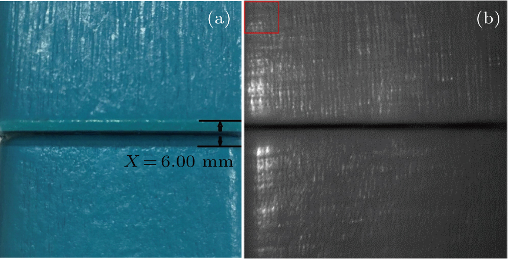
Two wooden blocks with step height are used as an object as shown in Fig. 9(a). Due to the small field of view of the wavefront coding optical system, the encoded image captured in CCD is a part of the object as indicated in Fig. 9(b). Figure 9(a) demonstrates the same part of the object for showing the consistency. Here X is 6.00 mm.
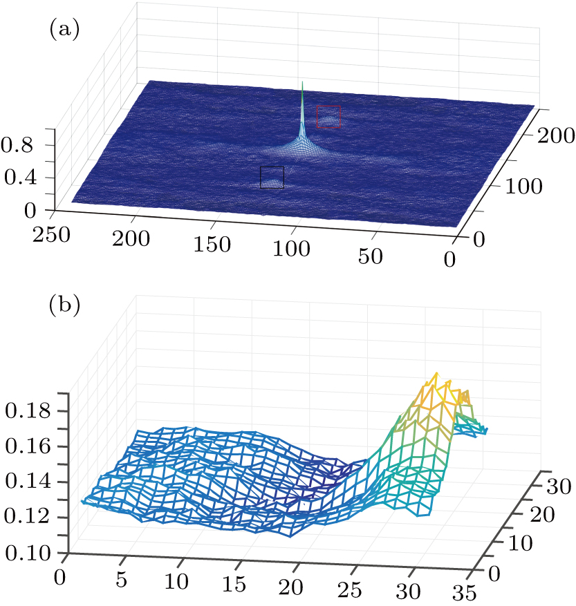
The encoded image is divided into a number of sub-images which will be analyzed to obtain the object distance of each sub-image. All sub-images are then processed separately to determine their local ranges.[4] The encoded image shown in Fig. 9(b) is acquired by a CCD sensor and processed as a 1920×1920 8-bit frame, and divided into 8×8 sub-images. A sub-image identified in the red frame of Fig. 9(b) is taken for example. Figure 10(a) shows the result of Eq. (11) on the sub-image in the red square frame shown in Fig. 9(b). Two twin peaks are shown in Fig. 10(a) in the black and the red square frame respectively. The enlarged image of the twin peak, marked in a black square, is shown in Fig. 10(b). The positions of the twin peaks can be calculated. Thus we can calculate the slope of the line between the secondary peaks. The object distance information of the sub-image is achieved through the look-up table containing the relationship between the object distance and the slope. Similarly, taking the same operation on the rest of the sub-images, we can obtain the depth map of the object as shown in Fig. 11.
According to Fig. 11, the values of object distance variation
 of two surfaces of the blocks are about 5.89 mm and 12.19 mm, respectively. The step height between the two blocks is 6.30 mm, which is close to 6.00 mm. Although there are some certain errors, the depth map of the object is digitally decoded successfully. The errors can be reduced by dividing the encoded image into more sub-images, so that the resolution of the restored depth map will increase.
4. Conclusions and perspectivesThe system through chiral phase encoding is sensitive to the object distance. In this paper, we deduce the analytic relationships between the object distance and the point spread function, and between the object distance and the encoded image. The theoretical analysis shows that the point spread function has two spots, which will rotate with the variation of the object distance. In addition, the processed spectrum of the encoded image has twin peaks rotating with the variation of the object distance. Then the depth information is extracted from the twin peaks of the encoded image. The theoretical analysis is verified by a wavefront coding system with a chiral phase which is generated by a phase-only liquid-crystal spatial light modulator. Compared with the fixed phase mask, the phase generated by the liquid-crystal spatial light modulator is very flexible and can be adjusted in real time.
The resolution of the 3D image obtained in the experiment can be further increased. The images can be divided into more sub-images to achieve a smooth image. Furthermore, the denoising algorithms will be considered to extract the twin peaks of the encoded image in an easier way in future research. Generally, weakly textured objects are accurate when the spatial spectrum of the object is wide enough to cover at least a few characteristic fringes. The use of high definition phase encoded images can also improve the reconstruction accuracy of the depth map of the object.
In this paper, a passive ranging system is also analyzed from another point of view, and the intuitive relationship between the depth information and the encoded image is presented. It is believed that the present study is helpful in developing the passive 3D imaging technology.


