Areal density and spatial resolution of high energy electron radiography
Xiao Jiahao1, 2, Zhang Zimin1, Cao Shuchun1, †, Yuan Ping1, Shen Xiaokang1, Cheng Rui1, ‡, Zhao Quantang1, Zong Yang1, Liu Ming1, Zhou Xianming1, Li Zhongping1, Zhao Yongtao1, Tang Chuanxiang3, Huang Wenhui3, Du Yingchao3, Gai Wei1, 3, 4
Institute of Modern Physics, Chinese Academy of Sciences, Lanzhou 730000, China
University of Chinese Academy of Sciences, Beijing 100049, China
Department of Engineering Physics, Tsinghua University, Beijing 100084, China
Argonne National Lab, Argonne, IL 60439, USA


† Corresponding author. E-mail: caosch@impcas.ac.cn chengrui@impcas.ac.cn

Abstract

Ultrafast imaging tools are of great importance for determining the dynamic density distribution in high energy density (HED) matter. In this work, we designed a high energy electron radiography (HEER) system based on a linear electron accelerator to evaluate its capability for imaging HED matter. 40 MeV electron beams were used to image an aluminum target to study the density resolution and spatial resolution of HEER. The results demonstrate a spatial resolution of tens of micrometers. The interaction of the beams with the target and the beam transport of the transmitted electrons are further simulated with EGS5 and PARMELA codes, with the results showing good agreement with the experimental resolution. Furthermore, the experiment can be improved by adding an aperture at the Fourier plane.

PACS: 52.70.-m
1. Introduction

High energy density (HED) matter is usually defined as matter in the state of deposited energy larger than 1011 J/cm3 or, equivalently, pressure higher than 1 Mbar. This state of matter is widespread in the universe stars and centrosphere. Furthermore, HED matter is also an important state for the inertial confinement fusion (ICF) processes. The physical properties of the matter at the extreme states are the most interesting for high energy density physics (HEDP) research: for instance, the knowledge of spatial distribution and temporal evolution of the temperature, volume, pressure, and density of HED matter are required for conducting experiments. In ICF/HEDP research, the fuel capsule density can be varying dramatically, from 0.02 g/cm3 to 400 g/cm3, with the spatial scale strongly compressed from 3 mm to on the scale of tens of ns. Meanwhile, the pressure increases to 1 Mbar; thus, the hydrodynamic response, as a highly enhanced velocity, will be on the scale of km/s. To obtain the fast-changing properties of matter in the case of high temperature, high pressure, and high density, the spatial and temporal resolution, as well as the areal density, are strictly limited. In addition, the diagnostic system must be sensitive to a mixture of high-Z and low-Z elements as well, because it is essential to measure the moving boundary and the proportions of different materials in order to understand the hydrodynamic processes in the HED sample.

Many ultrafast imaging diagnostic tools are based on the use of hard x-rays, Gamma rays, electrons, protons, and carbon beams, or even neutron beams produced by high power lasers or other pulsed power devices.[110] High energy proton radiography developed at Los Alamos National Laboratory (LANL) has shown its great potential for HED matter diagnostics with excellent spatial and temporal resolutions.[1113] This technique is also proposed at the Facility for Antiproton and Ion Research (FAIR) with 4.5 GeV proton beams.[14,15] Although a proton beam is superior to an electron beam in terms of penetration ability, a high energy proton accelerator and the corresponding imaging system are very costly, and a ps-scale proton beam bunch with desirable energy and intensity for radiography is not yet available in the laboratory. In addition, a proton radiography facility is always much larger in size than an electron radiography system. Furthermore, many other diagnostic methods, e.g., using the runaway electrons, are also applied to study the plasma characteristics.[16]

High energy electron radiography (HEER) is important to implement experimentally because of the great potential in the diagnostics of HED matter. So far, the reported radiography has achieved spatial resolution by using 30 MeV electron beams at LANL.[17] However, the resolutions for time and density are not systematically investigated. In particular, the new technology of ultrashort pulse laser coupled radio-frequency (RF) acceleration is applied in current electron accelerators, and high-quality electron beams with ultrashort bunch structure are now available in HEER. This paper reports on experimental HEER investigation carried out by Institute of Modern Physics (IMP), Chinese Academy of Sciences (CAS) and Tsinghua University (THU), based on the THU 50 MeV linear electron accelerator (LINAC) facility. The preliminary results confirm that the high areal density resolution and spatial resolution can be obtained by using the picosecond pulse-width electron radiography, which can be applied for HED matter diagnostics.

2. Principles of HEER

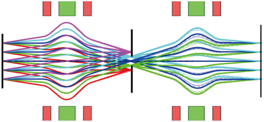
The high energy short pulsed electron beams have energy spreading and angle scattering after passing through the specimen. The electrons with angle and energy distributions can be refocused on the screen by the magnetic lens system. The electrons arrived at the area on the screen are the electrons emitted by the corresponding area on the target, thereby enabling point-to-point imaging. The intensity of photons is proportional to the electron count on the screen; thus, different intensities show the areal density distribution from the corresponding location. The chromatic aberration of the electron beams can be reduced by using an aperture at the Fourier plane of the magnetic lens. Figure 1 shows a schematic diagram of HEER.

Fig. 1. (color online) Schematic diagram of HEER. The trajectories of different colors starting at the object location represent electrons scattered into various angles within the object. The Fourier plane is located at the midpoint of the lens, where a collimator is positioned. The position–angle correlation at injection determines the location of the Fourier plane and partially cancels second-order chromatic aberrations.

Two key aspects for the HEER application to HED matter diagnostics, namely spatial resolution and density resolution, are investigated in this paper. Related to the spatial resolution, the deviation of the electrons on the screen dominates in the point-to-point imaging technique. The deviation of electrons can be described by the following formula:

where is the collimation angle of the aperture, R12 is the transfer matrix first-order term, and Mx is the magnification factor.[18]

The interaction of high energy electron beams with materials is very complex. However, only the multiple scattering, ionization, and bremsstrahlung processes need to be considered in our case. For high energy electrons, Coulomb scattering introduces a certain distribution when the electrons are travelling in the target. The energy loss experienced by the electrons is mainly due to the bremsstrahlung and ionization processes.

All the processes related to the electron beam going through the target and transported in the beam line will result in a loss of electrons. The transmission of the monoenergetic electron beam going through the target as a function of the target mass thickness can be given by a binomial formula.[19] Therefore, the areal density can be extracted from the transmission. Meanwhile, the transmission relates to the initial energy of the electron beam. For the point-to-point imaging system, the transmission is also influenced by the settings of the beam line. The scattering angle plays an important role in the imaging quality. Molière’s multiple scattering theory gives the distribution of the electrons scattering angle after the target, which can be written in the following way:

where
Equation (2) shows that the angle distribution is a Gaussian distribution relative to the target thickness and for constant energy; further, there exists a significant linear correlation between the FWHM of the Gaussian distribution and the electron energy in the same target thickness. Thus, increasing the incident electron energy can induce the transmission of electrons in the aperture collimating angle and increase the range of the density diagnostics simultaneously.

3. Experimental design

The HEER system was commissioned at the THU linear electron accelerator. The electron beam and lens system are designed as shown in Fig. 2. The electron beams were produced from the RF photocathode electron gun and accelerated at an energy of 46.2 MeV. The intensity was ∼100 pC, and the emittance was . The diameter of the beam spot on the target was ∼3 mm, and the bunch length was ∼1 ps; the momentum divergence was less than 1%. The lens is formed by two triplets, and the maximum of the magnetic field gradient is 12 T/m. An AYAG scintillator, a 45° reflection mirror, and a 16 bit CCD were employed to record the radiographs.

Fig. 2. (color online) Sketch of the HEER based on THU LINAC.

A step-wise aluminum target used as the sample was placed at the object plane; the thicknesses of the six steps were 7, 14, 28, 56, 112, and , with width for each step. The target structure is shown in Fig. 3.

Fig. 3. Schematic diagram of the aluminum step target.
4. Results and discussion

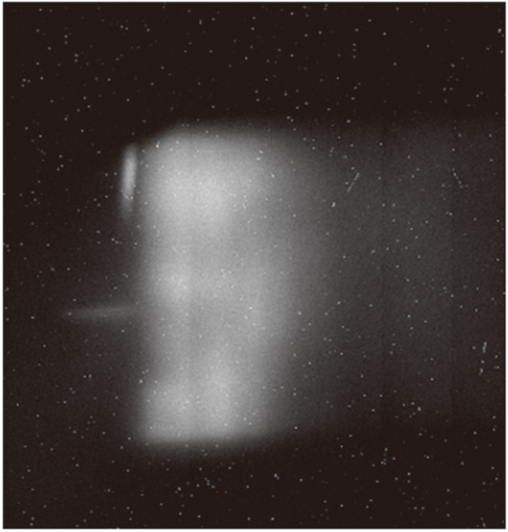
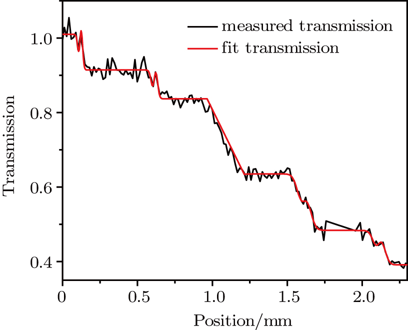
The recorded image of the Al ladder target is shown as Fig. 4. The transmission of the region is set to 1.0. To reduce the influence of the edge of the target frame, the pixels can be picked along the horizontal direction at the area with a higher contrast located away from the edge of the image. The magnification of the image is ∼0.68. The result of restoring the image to 1:1 and normalization is shown in Fig. 5. The transmission distribution in the x-axis is shown in Fig. 5. The red line is a fit with the assumption of a Gaussian line spread function resulting in the RMS width of the adjacent two steps. The RMS spatial resolution is presented in Table 1.

Fig. 4. Image of the aluminum step target recorded by HEER. The thickness of the target increases from the left of the picture to the right. The dark background around the target is due to the target holder frame blocking the electron beam.
Fig. 5. (color online) Transmission across each step shown in Fig. 4. The black line is the measured transmission, and the red line shows the fitted result using a Gaussian line spread function with an RMS width for each step of tens of micrometers.
Table 1.

RMS spatial resolution of the 46.2 MeV HEER experiment. The RMS width is obtained from the fit line shown in Fig. 5.

.

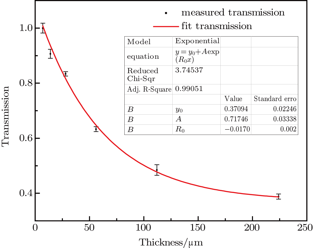
The transmission of each step can be found by fitting the line in Fig. 5, with the result shown in Fig. 6. The dependence of the transmission on the target thickness can be characterized by an exponential within the experimental error. Consequently, good areal density estimation can be obtained by the 46.2 MeV electron beam radiography measurement.

Fig. 6. (color online) Transmission for different thicknesses of the target.
5. Simulation

Simulations were performed to study the influence of the aperture size at the Fourier plane on HEER.

5.1. Theoretical model

In simulations, we calculated the delivery of electrons that hit the target and later propagate in the magnetic field and refocus on the screen. There are two specific processes that were considered in the simulations: the EGS program was used to calculate the interaction between the 40 MeV electron beams and the aluminum stepwise target that we used in the experiment; the other process is the electron transport in the two triple-magnet lens system after the target simulated with the PARMELA code.[20,21] The influence of the aperture size at the Fourier plane on HEER is discussed theoretically.

The distribution of the electrons at the Fourier plane can be described by the following formula:

Here, is made very small by optimizing the beam line. Thus, the angle selected by the aperture mainly depends on . The following formula can be obtained:
The parameters of the beam line are shown in Tables 2 and 3.

Table 2.

Transfer matrix of the origin to focus.

.
Table 3.

Parameters of the lattice.

.

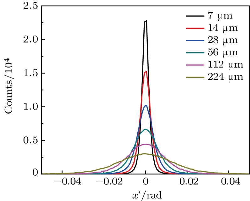
Figure 7 shows the distribution of the output electrons, and the sigma of the Gaussian fitting line is presented in Table 4.

Fig. 7. (color online) Angle distribution of the electrons after passing through the target with varying thickness.
Table 4.

Sigma of the Gaussian function fitting the angle distribution.

.
Table 5.

RMS spatial resolution obtained in the 40 MeV HEER simulations. The block letters in Table 2 represent the position in the target with varying thickness as shown in Fig. 3.

.

In this work, is set to 8 mm and 4 mm. For the 8 mm width aperture, the scattering angle ranges from −3.6 mrad to 3.6 mrad. For the 4 mm width aperture, the scattering angle ranges from −1.8 mrad to 1.8 mrad.

5.2. Results and analysis

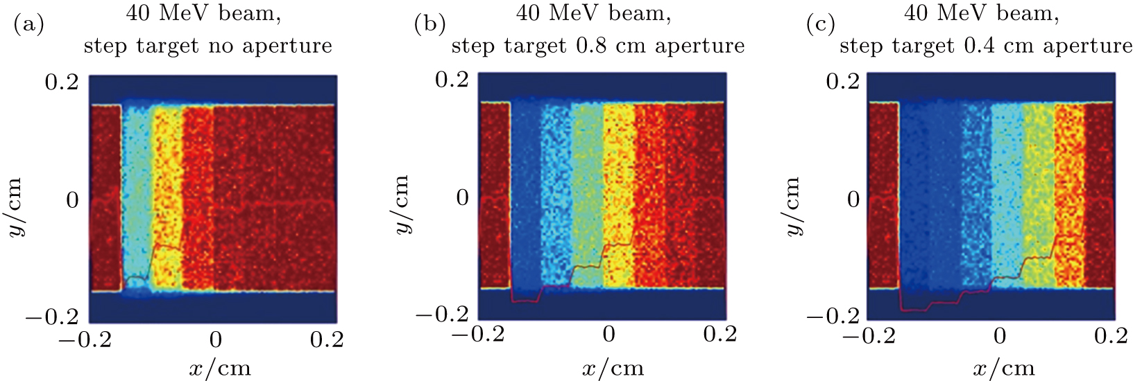
Using apertures of different size at the Fourier plane, we simulate the images shown in Fig. 8. It can be clearly seen that the aperture improves the HEER images resulting in a better contrast.

Fig. 8. (color online) Simulated images of the step target with (a) no aperture, (b) 8 mm size aperture, and (c) 4 mm size aperture at the Fourier plane in the x-axis. Lighter areas correspond to more electrons. The target for the imaging is the same as shown in Fig. 3. The thickness of the step shown in the imaging decreases from the left to the right of the image. The left and right edges are blank in the simulations.

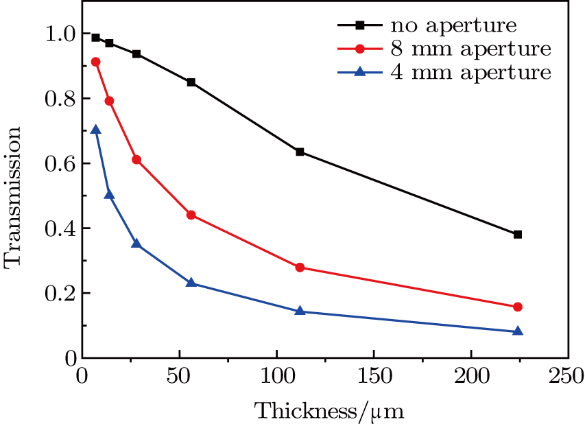
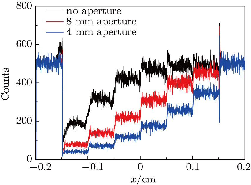
Figure 9 shows the simulated transmission as a function of the target thickness, for the three discussed cases including that of the unlimited aperture, 8 mm side length aperture, and 4 mm side length aperture. The density resolution is positively correlated with the slopes of the curves. The decrease of the aperture size causes the curves to move downward; as a result, a higher density resolution can be achieved. Simultaneously, a similar effect occurs for the areal density resolution.

Fig. 9. (color online) Transmission across each step for the cases of no aperture (black), 8 mm side length aperture (red), and 4 mm side length aperture (blue) at the Fourier plane.

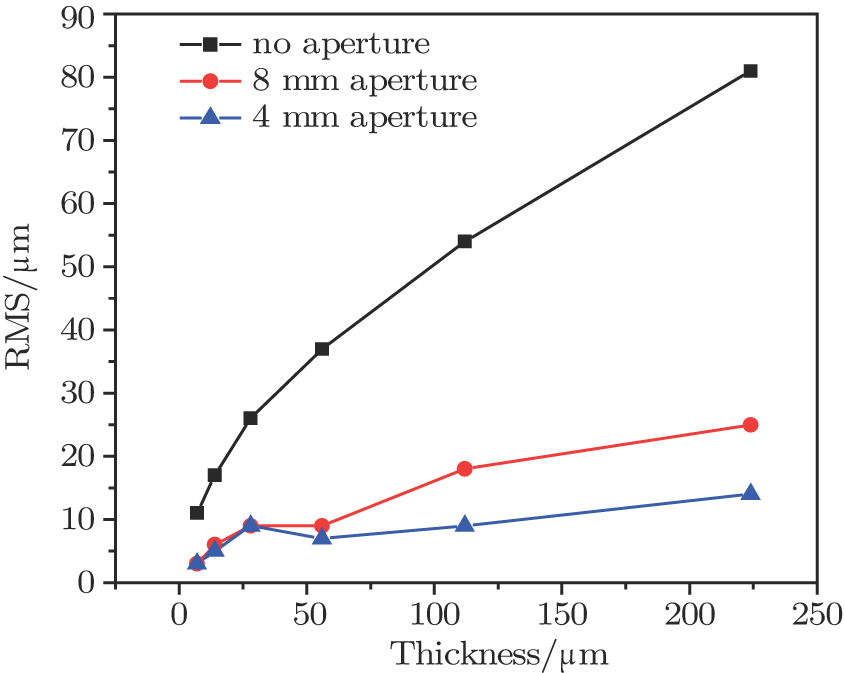
The distribution of the electrons on the screen is shown in Fig. 10. The RMS spatial resolution for different thickness gradient can also be obtained by Gaussian line spread fitting, with the corresponding results shown in Table 1. Figure 11 shows the RMS spatial resolution for each step obtained with apertures of different size. Using the contrast of the RMS spatial resolution obtained with apertures of different size at the Fourier plane, we can find that the effect of the aperture is clearly to improve the RMS spatial resolution. Based on these results, different size of the aperture can be selected for the required spatial resolution.

Fig. 10. (color online) Electron distribution along the x-axis.
Fig. 11. (color online) RMS spatial resolution for each step with no aperture (black), 8 mm side length aperture (red), and 4 mm side length aperture (blue) at the Fourier plane.
6. Conclusion

The experimental result of radiography measurements using the 46.2 MeV electron beams agrees well with the simulations for 40 MeV HEER on an aluminum step target, giving the RMS spatial resolution on the order of tens of micrometers. The transmission of the electron beams for different areal densities were investigated experimentally. The influence of the diameter of the aperture placed at the Fourier plane was discussed, showing that smaller apertures can improve the spatial resolution to several micrometers and make the transmission more sensitive to the areal density. In summary, the result of the experiment is consistent with the simulations, demonstrating that the LINAC with an ultra-short pulsed electron bunch is suitable for HEER applications.

Reference
[1] Edwards R D Sinclair M A Goldsack T J Krushelnick K Beg F N Clark E L Dangor A E Najmudin Z Tatarakis M Walton B Zepf M Ledingham K W D Spencer I Norreys P A Clarke R J Kodama R Toyama Y Tampo M 2002 Appl. Phys. Lett. 80 2129
[2] Beg F N Krushelnick K Lichtsteiner P Meakins A Kennedy A Kajumba N Burt G Dangor A E 2003 Appl. Phys. Lett. 82 4602
[3] Li C K Seǵuin F H Rygg J R Frenje J A Manuel M Petrasso R D Betti R Delettrez J Knauer J P Marshall F Meyerhofer D D Shvarts D Smalyuk V A Stoeckl C Landen O L Town R P J Back C A Kilkenny J D 2008 Phys. Rev. Lett. 100 225001
[4] Roth M Jung D Falk K et al. 2013 Phys. Rev. Lett. 110 044802
[5] Zhao Q Cao S Ch Cheng R Shen X Zhang Z Zhao Y Gai W Du Y 2014 Proceedings of LINAC2014, 31 August–5 September, 2014, Geneva Switzerland MOPP015
[6] Zhao Y Zhang Z Gai W et al. 2016 Laser Part. Beams 34 338
[7] Zhao Q Cao S Ch Liu M Shen X K Wang Y R Zong Y Zhang X M Jing Y Cheng R Zhao Y T Zhang Z M Du Y C Gai W 2016 Nuclear Instruments and Methods in Physics Research 832 144
[8] Zhao Y Cheng R Wang Y Zhou X Lei Y Sun Y Xu G Ren J Sheng L Zhang Z Xiao G 2014 High Power Laser Sci. Eng. 2 E39
[9] Wu X J Wang X F Chen X H 2016 Chin. Phys. Lett. 33 065201
[10] Dong J J Cao Z R Yang Z H Cheng B L Huang T X Den B Liu S Y Jiang S E Ding Y K Yi S Z Mu B Z 2012 Acta Phys. Sin. 15 155208 in Chinese
[11] King N S P Ables E Adams K et al. 1999 Nuclear Instruments and Methods in Physics Research 424 84
[12] Merrilla F E Campos E Espinoza C Hogan G Hollander B Lopez J Mariam F G Morley D Morris C L Murray M Saunders A Schwartz C Thompson T N 2011 Rev. Sci. Instrum. 82 103709
[13] Merrill F E 2015 Laser Part. Beams 33 425
[14] Merrill F E Golubevc A A Mariama F G Turtikovc V I Varentsovb D HEDge H O B 2009 AIP Conf. Proc. 1195 667
[15] Varentsov D Shutov A Lomonosov I V Golubev A A Kantsyrev A Lang P M Nikolaev D N Markov N Natale F Shestov L Simoniello P Smirnov G N Durante M 2013 Phys. Medica 29 208
[16] Zheng Y Ding X Li W 2006 Chin. Phys. 15 1035
[17] Merrill F Harmon F Hunt A Mariam F Morley K Morris C Saunders A Schwartz C 2007 Nuclear Instruments and Methods in Physics Research 261 382
[18] Brown K L 1971 A First- and Second-Order Matrix Theory for the Design of Beam Transport Systems and Charged Particle Spectrometers, SLAC Report No. 75
[19] Odeblad E 1957 Acta Radiologica 48 289
[20] Hirayama H Namito Y Bielajew A F et al. 2005 The EGS5 Code System [R]
[21] PARMELA, 27th Oct. 2014 http://laacg.lanl.gov/laacg/services/serv_codes.phtml