The physical characteristics of a plasma arc affect the stability of the keyhole and weld pool directly during keyhole plasma arc welding (KPAW). There will be significant change for these characteristics because of the interaction between the keyhole weld pool and plasma arc after penetration. Therefore, in order to obtain the temperature field, flow field, and arc pressure of a plasma arc under the reaction of the keyhole, the physical model of a plasma arc with a pre-set keyhole was established. In addition, the tungsten and base metal were established into the calculated domain, which can reflect the effect of plasma arc to weld pool further. Based on magneto hydrodynamics and Maxwell equations, a two-dimensional steady state mathematical model was established. Considering the heat production of anode and cathode, the distribution of temperature field, flow field, welding current density, and plasma arc pressure were solved out by the finite difference method. From the calculated results, it is found that the plasma arc was compressed a second time by the keyhole. This additional constraint results in an obvious rise of the plasma arc pressure and flow velocity at the minimum diameter place of the keyhole, while the temperature field is impacted slightly. Finally, the observational and metallographic experiments are conducted, and the shapes of plasma arc and fusion line agree with the simulated results generally.
Welding with penetration of plasma arc is an ideal method to join thick metal plate because it can weld one pass with backside formation.[1] To compare with other high energy beam welding, keyhole plasma arc welding method (KPAW) has the advantages of low cost and easy operation. However, the stability of KPAW will become weak as the welding current increases and some welding defects will appear because of the unstable plasma arc with strong penetrating force. Moreover, there is a violent interaction among plasma arc, weld pool, and keyhole, which can make the physical characteristics change complicatedly. Similar to the compressed effect of nozzle, the keyhole causes an additional constraint to plasma arc. Arc pressure, velocity, and temperature become more complex under the additional constraint effect. Furthermore, the formation and stability of keyhole weld pool are affected. So it is helpful for better understanding the KPAW process by investigating the physical characteristics of plasma arc and weld pool under the additional constraint effect of the keyhole.
Numerical simulation has been an effective method to study the welding process because the computer technology and numerical theory develop rapidly. Regarding to the simulation of welding arc, early articles mostly focused on the solution of arc region without considering the electrode, base metal, and their interactions.[2–5] Then, in order to avoid the artificial assumption of welding current on the tungsten tip, a fluid and solid coupling calculation was conducted by considering tungsten into the calculated domain.[6] Based on the previous models, including energy source terms on surfaces of electrode and base metal, the unified calculated models were established to analyze the heat and mass transfer between arc and base metal.[6–14] Subsequently, researchers began to use these models to study more complex factors which influenced the physical characteristics of welding arc. Fan et al.[15] presented a three-dimensional model of tungsten inert gas welding arc taking the behavior of metal vapor into account. Zhou et al.[16] numerically analyzed the influence of the surface topography of the deposited layer on arc in additive forming process. Through the above study of free arc, researchers has understood the mechanism of heat generation, distribution of arc physic field and energy transfer deeply.
However, for KPAW, modeling and calculation are more complicated because of the severe physical characteristics and keyhole effects. The special keyhole digging process of KPAW has been numerically analyzed by tracking the free surface of weld pool. The evolution of temperature and flow field in weld pool was quantitatively investigated by coupling keyhole deformation and thermal-mechanical effects.[17–20] Jian et al. and Pan et al.[21,22] developed a unified model of plasma arc welding by coupling the transport behavior between plasma arc and weld pool. The whole region consisted of the plasma arc, and weld pool, and the keyhole penetrating process was simulated at the same time. Moreover, Li et al.[23] established a more effective calculated model of KPAW by pre-set a simple keyhole to study the thermo-physical process.
Even though there have been a lot of study about KPAW, the evolution of the whole physical field under the additional constraint effects of a keyhole with efflux has not been investigated. Under the action of keyhole penetration, it is significant to control the formation of a back side weld bead. After full penetration, there is one more outlet for arc plasma, which has a serious impact on arc physical characteristics. Conversely, the plasma arc can affect the weld pool further. Therefore, for numerical analysis of KPAW, it is very necessary to establish a unified model including electrodes, plasma arc, and efflux to study the heat and force transfer in a more complete region. In this work, considering the interaction law on the cathode and anode, a unified model coupling plasma arc, weld pool, keyhole, and efflux is proposed to study the physical field in quasi-steady state of KPAW. Through this study the numerical model will be improved and it is also helpful to understand the transport phenomenon in KPAW further.
2. Simulated modeling
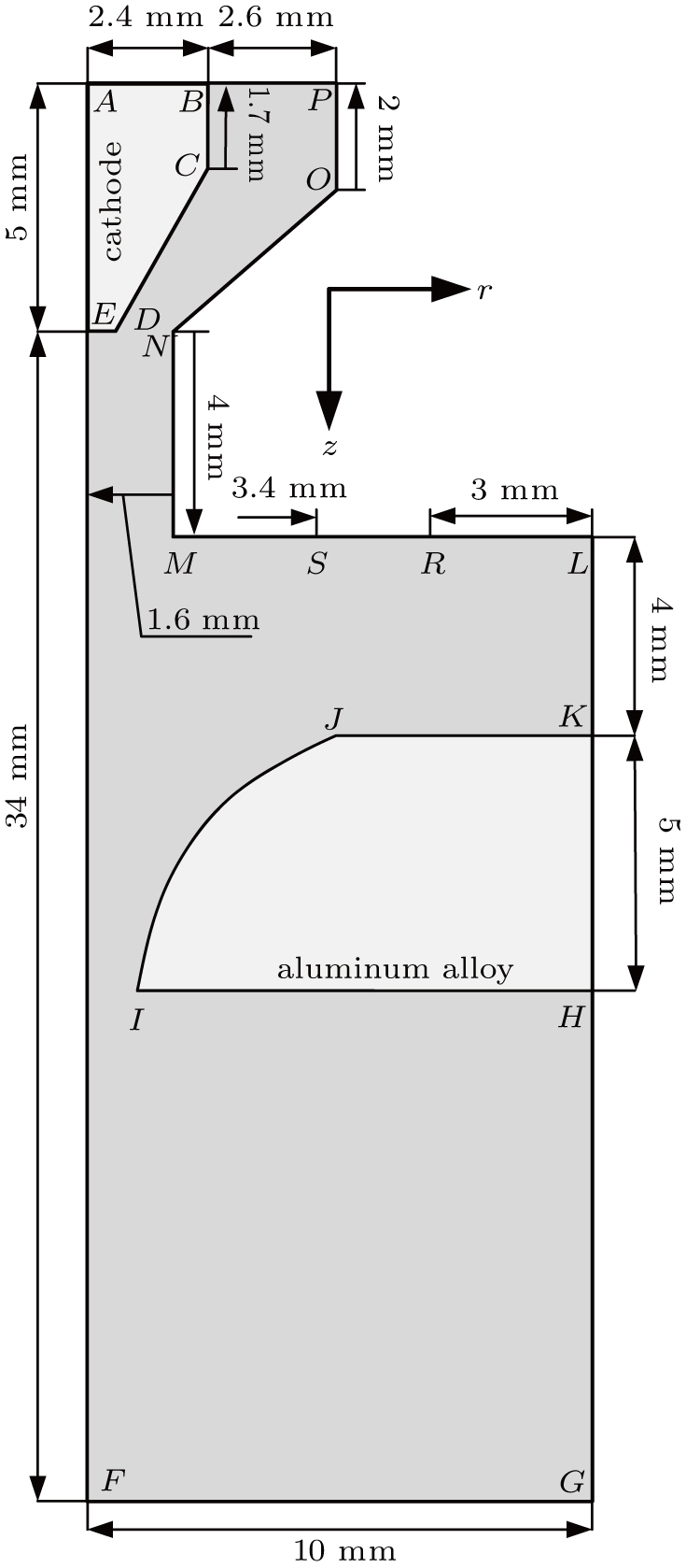
2.1. Calculated domain
Figure 1 shows the schematic illustration of the calculated domain which is assumed to be two-dimensional (2D) axisymmetric. The cathode (AEDCBA), base metal (KHIJ) and arc, efflux region (the rest) are considered in this domain. The equations are solved at the same time in these regions. The material of cathode is tungsten and its diameter is 4.8 mm. Electrode setback is 4 mm. Orifice diameter is 3.2 mm. The base metal is 5A06 aluminum. Plasma gas flows in from BP, then electric field produces heat in the gas region. HK on the base metal is potential zero and the cathode current density is set on AB, which avoids the assumption of the current density on the tip of tungsten. As an assumption, the keyhole boundary IJ is preset in the base metal based on the experimental measurement, then to study the constraint effect of the keyhole on the plasma arc. The calculated domain also comprises a gas region used to simulate efflux plasma below the base metal. Shielding gas flows in from the central region of ML.
The conditions used in the simulation are the same as those in experiments. Plasma gas and shielding gas are both argon. The flow rates are 2.0 L/min and 15 L/min, respectively. The welding current is 140 A. Arc length, the distance from ML to JK, is 4 mm.
2.2. MHD model
To mathematically model the arc, pool, and the interaction, we assume that (i) the plasma arc is in local thermodynamic equilibrium, (ii) the fluid is laminar, and (iii) the plasma arc is a continuous medium. The simplifications are made that (i) the viscous dissipation is neglected, (ii) the plasma arc is axisymmetric, and (iii) the metal vapor and fluid flow inside the weld pool are neglected. The direction of the gravity is the positive of the z axis. The latent heat of the metal evaporation is neglected.
Based on the above assumptions, the governing equations are described as
(i) mass conservation:
(ii) radial momentum conservation:
(iii) axial momentum conservation:
(iv) energy conservation:
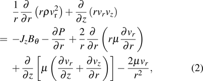
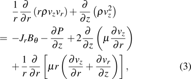
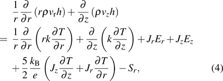
where ρ is density, vr and vz are the components of velocity at different directions, Jr and Jz are the components of current density, Bθ is magnetic induction, P is pressure, μ is viscosity coefficient, T is temperature, k is thermal conductivity, Er and Ez are the radial and axial components of electric field intensity, e is one electrical charge, kB is Boltzmann constant, and Sr is radiation loss.
There is the term of Lorenz force in momentum conservation and Joule heat term in energy conservation. So the Maxwell equations need to be solved to get the distribution of magnetic induction B and current density J, which is shown as
Ohmʼs law:
current continuity equation:
radial Poisson equation of magnetic vector potential:
axial Poisson equation of magnetic vector potential:
magnetic induction:
where σ is electric conductivity, ϕ is electric potential, Ar and Az are magnetic vector potential in radial and axial direction, and is the permeability of a vacuum.
An additional energy source term which can describe the thermal and flux that occurs only at the electrode is needed. The additional heat flux at the cathode includes thermionic cooling, ion heating, and radiation cooling, which is defined as
where Ji is ion current density, vi is ionization potential of argon, Je is electron current density, ϕk is the work function of tungsten, ε is surface emissivity, and α is the Stefan–Boltzmann constant. Because of the thermionic emission of electrons at the cathode surface, Je cannot exceed the Richardson current density[13]
where A is the thermionic emission constant of the cathode and φe is the effective work function for thermionic emission of the electrode surface at local surface temperature. The ion current density Ji is then assumed to be if is greater than , where is total current density at the cathode surface calculated from the current continuity equation.
At the anode surface, it also needs an additional energy source term of heating by electron condensation and radiation cooling, which is written as
where ϕA is the work function of base metal.
2.3. Boundary condition
The boundary condition is set according to the actual welding process as shown in Table 1. AB is the cross section of tungsten where current density and temperature are given. BP is the mass flow inlet of plasma gas and RS is the mass flow inlet of shielding gas. KH is the outside surface of base metal. The heat transfer condition is given as
where q is the total heat loss, qc and qr are heat loss by convection and radiation respectively, he is convection heat transfer coefficient, is ambient temperature, and Tw is base metal surface temperature. Since the tungsten is cooled by 8 °C water, the temperature on the section AB is specified as 300 K. On the boundary close to the plasma arc region, the temperature is set to 1000 K while that far away from the arc is 300 K.[21]
Table 1.
Table 1.
Table 1.
Boundary conditions.
.
Boundary
T/K
ϕ/V
AB
–
300
BP
1000
PO, ON, NM, MS, RL
–
1000
AE, EF
RS
1000
LK, HG, GF
300
KH
–
Eq. (12)
0
Note: —velocity vector, —unit vector normal to the surface, —velocity constant based on gas flow rate, and is magnetic vector potential.
Table 1.
Boundary conditions.
.
3. Results and discussion
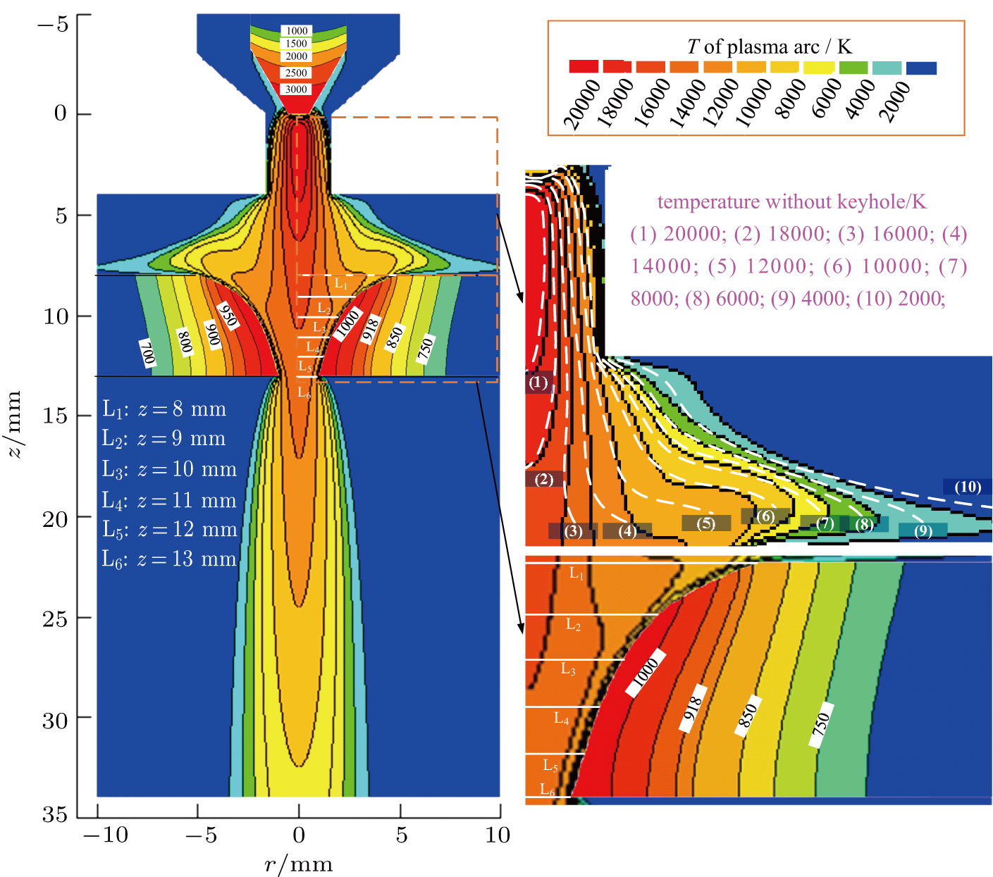
Figure 2 shows the temperature field of plasma arc, base metal, tungsten, and efflux plasma with the keyhole. The plasma arc between the nozzle and base metal still is bell shaped. But comparing to that without a keyhole, which is shown by the white dotted line in the magnified image, the temperature field close to the base metal shrinks a little to the center. Below that, the plasma arc changes the shape with the recompression of the keyhole, which is similar to the compressing action of the nozzle. Because the diameter of the keyhole gradually decreases along the thickness direction, the compressing action by the keyhole is enhanced. The radial temperature gradient increases while the axial temperature gradient decreases because it is unimpeded for axial flow. Then from the temperature of efflux plasma, it can be seen that once the plasma arc is out of the keyhole below the base metal, the radial distribution of arc temperature field increases immediately. Relying on the above mentioned temperature field distribution, we can easily see that the keyhole has a great influence on the plasma arc.
Fig. 2. (color online) Temperature field of plasma arc and base metal.
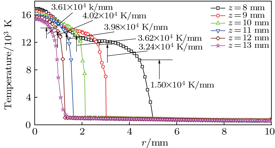
Figure 3 shows the temperature of different lines inside the keyhole. The temperature distribution along the radial direction is almost the same. From the center to the outside, the temperature decreases and pelts in the near boundary region. The temperature gradient is calculated on the boundary layer which is from the point of beginning to rapidly decrease to the keyhole boundary. It is 1.5×10⁴ K/mm on the line of z = 8 mm and then the temperature gradient on the boundary layer increases as the keyhole depth increases. It increases to the maximal value 4.02×10⁴ K/mm in the line of z = 12 mm. On the contrary, in the line of z = 13 mm where the diameter of the keyhole is minimum, the temperature gradient decreases to 3.61×10⁴ K/mm. The reason is analyzed that the temperature is almost the same in a high level on the keyhole boundary with a small diameter because it closes to the center of the plasma arc.
Fig. 3. (color online) Distribution of temperature on the lines inside keyhole.
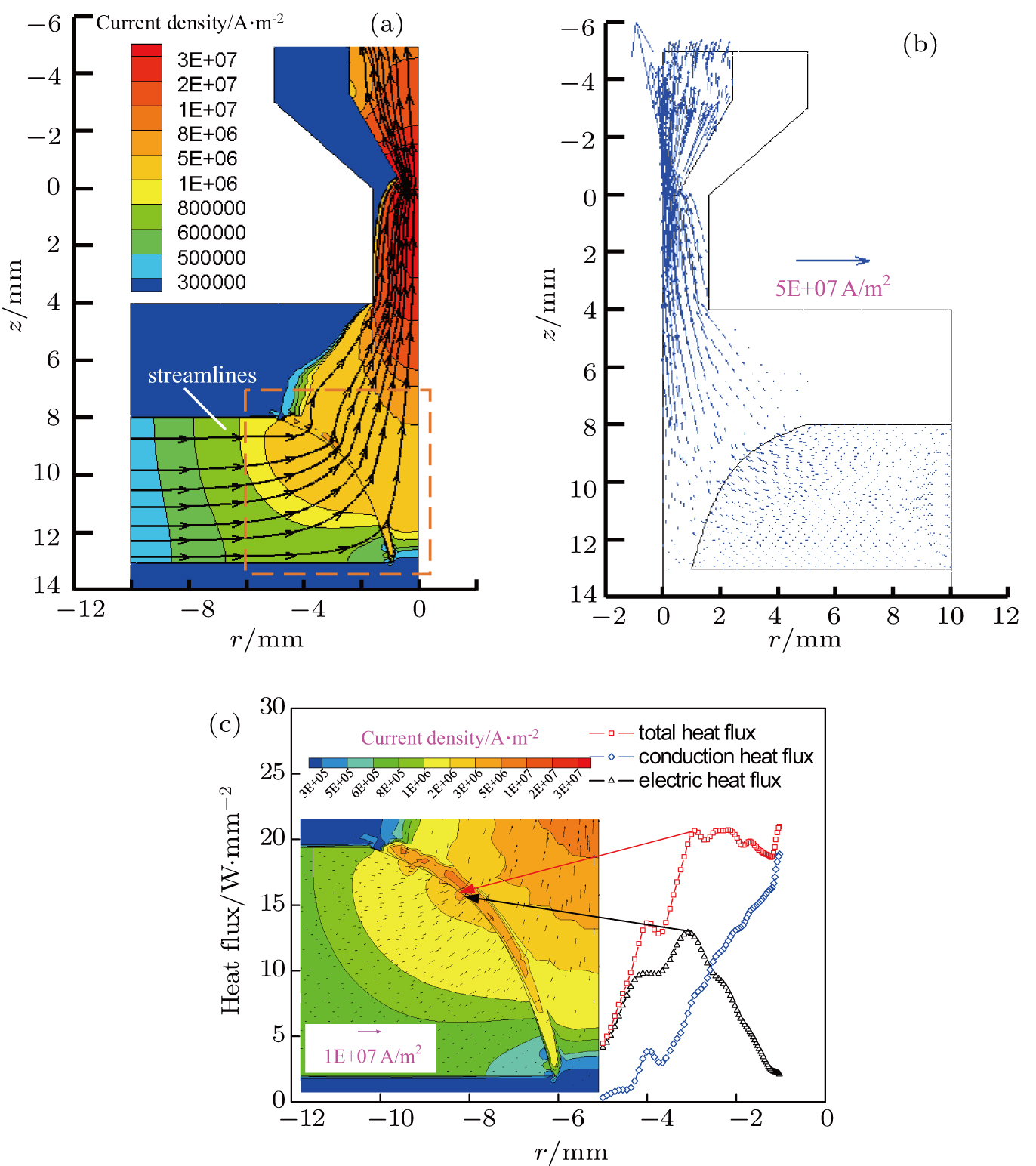
Figure 4 shows the distribution and vector of current density. The maximum value occurs at the tip of tungsten. From the streamlines of current density, it can be seen that welding current flows from base metal to tungsten and it mainly flows through the upper part of the base metal. This kind of distribution directly determines the heat transfer from plasma arc to base metal on the keyhole boundary. The heat flux distribution along the keyhole boundary is shown in Fig. 4(c). The distributed curves of heat flux on the boundary of the keyhole indicate that the total heat flux is mainly determined by the heat flux of electron and thermal conduction. There is a peak value of electric heat flux at the region of maximum current density. The maximum value of conduction heat flux appears on the bottom of the keyhole. So through this distinguishing feature of heat flux, we can conclude that when the keyhole is established, the heat on the upper part of the weld pool mainly comes from electric heat and that on the lower part mainly from thermal conduction.
Fig. 4. (color online) Distribution of current density and heat flux on the keyhole boundary. (a) Distribution contour and flow direction, (b) vector, and (c) heat flux.
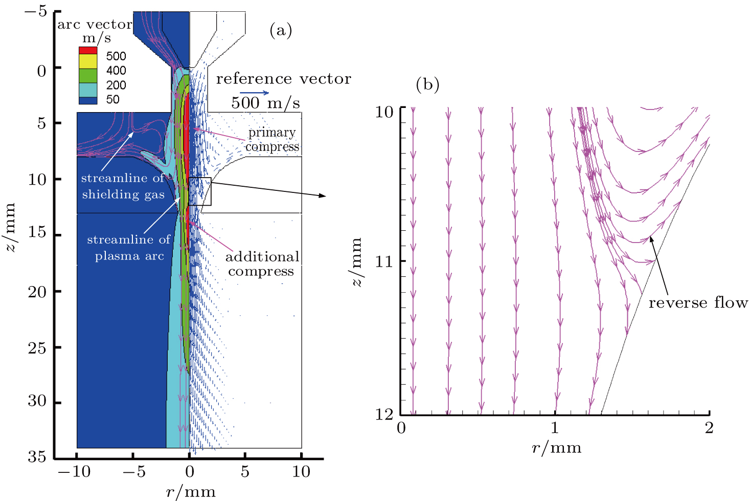
Figure 5 shows the velocity field of plasma arc and the fluid flow vector under keyhole additional constraint. Maximum velocity appears in the center of the arc and the arc plasma flows outward in a radial direction and downward in an axial direction when the fully penetrated keyhole exists in the base metal. Velocity increases again under the additional compressing action of the keyhole after the primary compress of the nozzle. As the diameter of the keyhole becomes smaller gradually from the top side to the bottom side, the arc plasma is blocked by the boundary. So part of the arc plasma flowing into the keyhole has the phenomenon of reverse flow in the near keyhole boundary region. This reverse flow characteristic of plasma arc with the keyhole is the main reason causing irregular flow of liquid metal in the weld pool.[24]
Fig. 5. (color online) Velocity distribution of plasma arc and its vector. (a) Velocity in the whole region and (b) magnified reverse flow region.
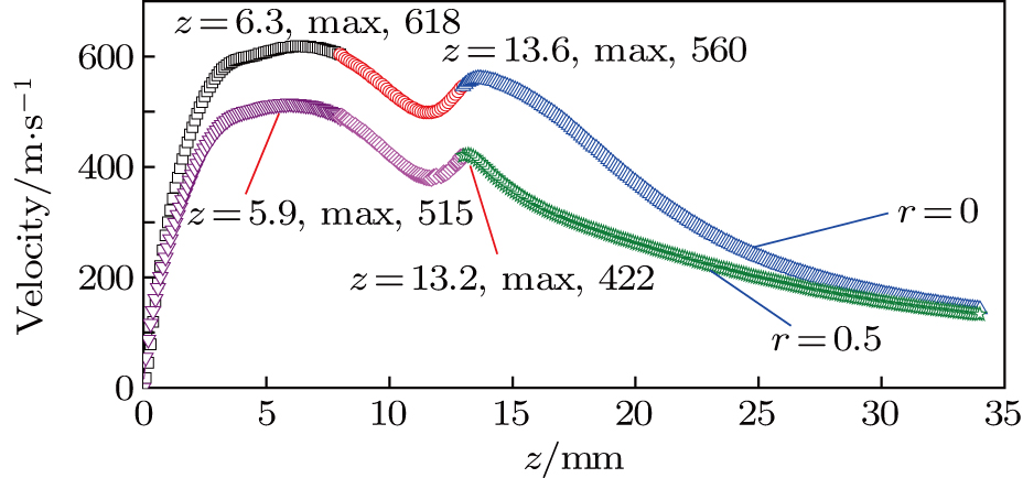
Figure 6 shows the velocity of plasma arc on lines of r = 0 and r = 0.5. There are two peaks of velocity on each line. The first one (z = 6.3 mm, 618 m/s for line of r = 0; z = 5.9 mm, 515 m/s for line of r = 0.5 mm) is because of the primary compress of the nozzle and the second peak (z = 13.6 mm, 560 m/s for line of r = 0; z = 13.2 mm, 422 m/s for line of r = 0.5 mm) is due to the additional compress of the keyhole.
Fig. 6. (color online) Velocity of plasma arc on two different lines.
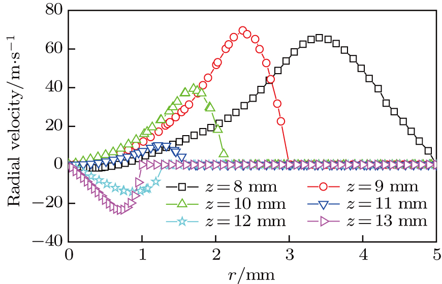
Figure 7 shows the radial velocity of arc plasma of different lines. From the radial velocity we can get the flowing outward characteristics of arc plasma inside the keyhole. For each line of z = 8 mm, z = 9 mm, z = 10 mm, and z = 11 mm, there is a positive peak value between the center of the plasma arc and the keyhole boundary, which indicates that the arc plasma extends to the outside fastest at the region with a certain distance from the central axis of plasma arc. From the results of z = 12 mm and z = 13 mm, it can be seen that the radial velocity is negative, which shows that the arc plasma flows to the center. Therefore, the conclusion can be got that arc plasma inside the keyhole over z = 11 mm can flow outward along the radial direction, while it can only flow downward below z = 12 mm. It also can indicate that the reverse flow occurs between z = 11 mm and z = 12 mm, which is clear in Fig. 5(b).
Fig. 7. (color online) Radial velocity of arc plasma on different lines inside the keyhole.
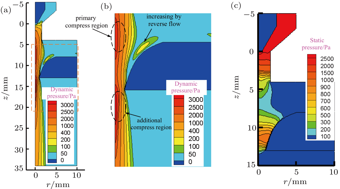
Figure 8 shows the plasma arc pressure distribution contour under the keyhole effect. According to the Bernoulli equation, dynamic pressure is represented by both density and velocity. The value of dynamic pressure increases under the compressed effect of the nozzle. Similar to the distribution of temperature field, radial pressure gradient is large with the constraint effect and the axis gradient is small due to the additional flow channel of the keyhole for arc plasma. Dynamic pressure has the same distribution as the flow velocity. It increases again under the effect of the keyhole. Due to the reverse flow of arc plasma, there is a dynamic pressure increasing zone near the upper side keyhole boundary. The increment of static pressure reflects the keyhole action to plasma arc directly, while the dynamic pressure is a characteristic of arc plasma based on fluid flow and temperature. From Fig. 8(c), it can be seen that the static pressure inside the keyhole also increases.
Fig. 8. (color online) Distribution of plasma arc pressure. (a) Dynamic pressure in the whole region, (b) magnified compressed region, and (c) static pressure distribution.
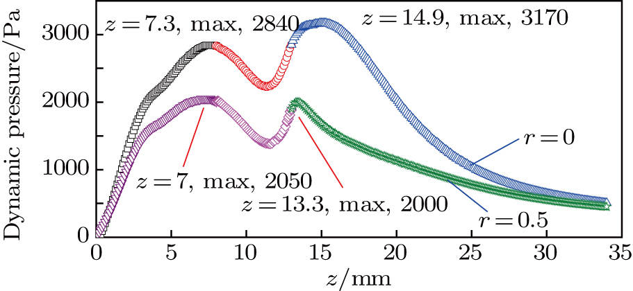
Similar to the distribution of velocity on the axis line, dynamic pressure reaches to a two peak value under the constraint of nozzle and keyhole. Respectively, on lines of r = 0 and r = 0.5 mm, the peak values are shown in Fig. 9.
Fig. 9. (color online) Dynamic pressure under additional constraint by keyhole.
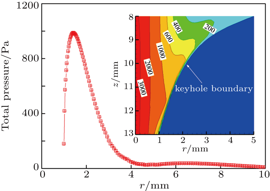
Figure 10 shows the distribution of plasma arc pressure on the surface of base metal with the keyhole. The curve shows that the maximum plasma arc pressure is not at the center after penetration. It is about 1000 Pa appearing near 1.5 mm in the radial direction. Then the pressure decreases gradually along the radial direction. After full penetration, the plasma arc pressure affected by the keyhole boundary becomes smaller than that on the boundary without the keyhole.[25]
Fig. 10. (color online) Plasma arc pressure on the surface of base metal with the keyhole.
4. Experimental verification
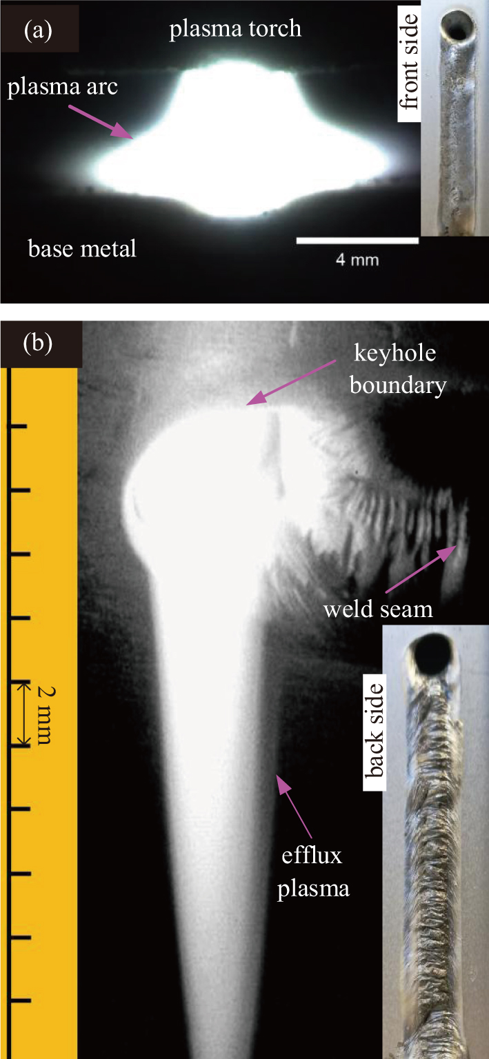
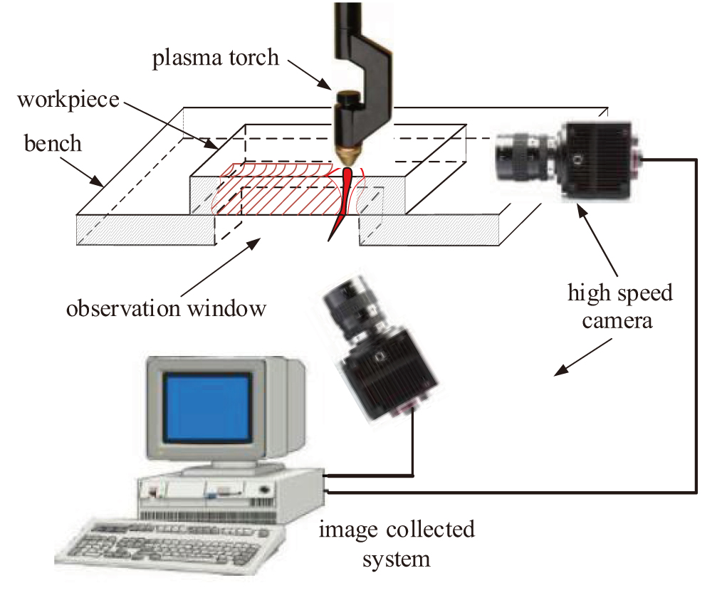
A high speed camera experiment platform is built to verify the calculated model, which is shown in Fig. 11. There are two CCD cameras in this experimental system. One of them is used to get the image of the plasma arc, while the other one is for efflux plasma. The amount of light into the lens is set at f15 and the exposure time is .
Fig. 11. (color online) Collected system of plasma arc and efflux images.
Figure 12 shows the images of plasma arc and efflux plasma. In Fig. 12(a), it shows that the shape of plasma arc in the front side after full penetration is basically the same as that calculated in Fig. 2. Moreover, for the efflux plasma, with the 10000 K temperature line as the boundary, the length of calculated efflux is about 20 mm which is similar with the experimental results of 18 mm, shown in Fig. 12(b).
Fig. 12. (color online) Images of (a) plasma arc of front side and (b) efflux plasma of bottom side.
Therefore, from the shape and size of plasma arc and efflux, it preliminarily indicates that the calculated model is reasonable.
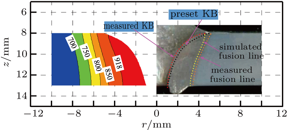
In addition, a plasma arc penetrating experiment was performed and the macrograph of the weld was made. Comparing the simulated and experimental results, it is shown that the fusion zone and keyhole size are in good agreement with each other, as shown in Fig. 13.
Fig. 13. (color online) Comparison of fusion line and keyhole boundary (KB).
5. Conclusion
The plasma arc temperature on the upside of base metal with a keyhole relatively shrinks to the center more than that without keyhole. The arc temperature gradient on the boundary increases as the depth of keyhole and decreases when close to the bottom of the keyhole.
The welding current mainly flows through the upper part of the keyhole. The heat on the upper part of the weld pool is produced both by electronic heat and heat conduction, while that on the lower part is provided mainly by heat conduction.
The second peak of arc pressure appears on the axis under the additional constraint of the keyhole. Plasma velocity has a similar characteristic with arc pressure and reverse flow occurs near the keyhole boundary.
Comparing the results of simulation and experiments, the shapes of weld, plasma arc, and efflux plasma are basically in agreement with each other.