


Anisotropic nanocomposite soft/hard multilayer magnets
Cite this Article
Liu Wei, Zhang Zhidong. Anisotropic nanocomposite soft/hard multilayer magnets. Chinese Physics B, 2017, 26(11): 117502 
Permissions
Anisotropic nanocomposite soft/hard multilayer magnets
† Corresponding author. E-mail:
Project supported by the State Key Project of Research and Development of China (Grant No. 2017YFA0206302), the National Nature Science Foundation of China (Grant Nos. 51590883, 51331006, and 51471167), and the Chinese Academy of Sciences (Grant No. KJZD-EW-M05-3).
Abstract
Experimental and theoretical researches on nanostructured exchange coupled magnets have been carried out since about 1988. Here, we review the structure and magnetic properties of the anisotropic nanocomposite soft/hard multilayer magnets including some new results and phenomena from an experimental point of view. According to the different component of the oriented hard phase in the nanocomposite soft/hard multilayer magnets, three types of magnets will be discussed: 1) anisotropic Nd2Fe14B based nanocomposite multilayer magnets, 2) anisotropic SmCo5 based nanocomposite multilayer magnets, and 3) anisotropic rare-earth free based nanocomposite multilayer magnets. For each of them, the formation of the oriented hard phase, exchange coupling, coercivity mechanism, and magnetic properties of the corresponding anisotropic nanocomposite multilayer magnets are briefly reviewed, and then the prospect of realization of bulk magnets on new results of anisotropic nanocomposite multilayer magnets will be carried out.
PACS:
75.50.Bb
Keyword:anisotropic multilayer magnets;exchange coupling;effective interaction length;coercivity mechanism
1. Introduction
Exchange couplings in magnetic thin films have attracted a great deal of attention in the areas of permanent magnets, magnetic recording, sensors, and spin electronics. The exchange-coupled permanent magnets are one of the model systems for studying the exchange couplings in magnetic thin films. The exchange-coupled magnets were firstly experimentally realized in ribbons by melt-spinning in 1988.[1] The merits of such magnets were a high saturation magnetization provided by a soft-magnetic phase and a mediate coercivity provided by a hard-magnetic phase if the two phases can be exchange-coupled well. Consequently, Kneller and Hawig[2] theoretically predicted a high maximum magnetic energy product and an unusually high remanence ratio or reduced remanence Mr/Ms, due to exchange coupling between nano-grains of the soft and hard magnetic phases. In addition, they predicted a unique magnetic behavior characterized by a reversible demagnetization curve, that is, a maximum recoil permeability as distinguished from the conventional single-phase permanent magnets, where the demagnetization curves reflect essentially the distribution of the irreversible switching fields. It is for this unique magnetic behavior of the nanocomposites, in a sense resembling a mechanical spring, that such magnets have been termed exchange-spring magnets by Kneller and Hawig. Skomski and Coey[3] attempted to predict the nucleation-field coercivities Hc = HN for three-dimensional two-phase nanostructures, which gave rise to a quantitative analysis of the permanent-magnet performance of oriented two-phase nanostructures. They predicted that the maximum energy product in suitably nanostructured Sm2Fe17N3/Fe65Co35 composites was as high as 1090 kJ/m3. But the maximum energy products of the rare-earth nanocomposite magnets prepared by means of rapid quenching and mechanical alloying have been much lower than the theoretical expectation, due to difficulties in controlling the nanostructures.[4–7] Although the remanence enhancement effect has been observed due to effective exchange coupling between hard and soft phases in such a bulk hard/soft phase system, the squareness of the demagnetization curve of the samples was not good enough for obtaining a higher energy product than that of the single phase, in which the hard phase is isotropic. The higher maximum energy product (BH)max was possible if the particle size (or layer thickness) of the soft-magnetic phase did not exceed the domain thickness of the hard-magnetic phase. However, in bulk samples, it was not so easy to control the microstructure compared with thin films. So, many works have been done on multilayer films or nanostructured films with Nd–Fe–B, PtFe, SmFe or SmCo as the hard magnetic phase.[8–13] Later, based on the summary and analysis of previous work on nanostructured exchange-coupled magnets[14] and our work on exchange couplings in magnetic films,[15] it was realized that the higher energy product may be obtained in anisotropic exchange-coupled multilayer magnetic films.
However, it is difficult to prepare anisotropy nanocomposite permanent magnets due to the difficulties in controlling the formation and alignment of the hard phase and diffusion between the hard and soft phases. It is well known that the temperature of the formation of the hard phases such as Nd2Fe14B, SmCo5, and FePt should be above their crystallization temperature, for example, 550 °C. In addition, if the oriented hard phase is obtained, the anisotropic film will be directly epitaxially grown on single crystal substrates at high temperatures or at low temperatures following subsequent annealing at higher temperatures. It is easy to realize an anisotropic film of a single hard phase layer by means of the preparation method mentioned above, but for a multilayer with hard and soft phases, the formation and alignment of the hard phase are easily destroyed by diffusion of the soft phase at high temperatures. In order to solve this problem, Cui et al. realized an anisotropic soft- and hard-magnetic (SM and HM) nanocomposite multilayer by inserting a non-magnetic spacer layer to prevent diffusion between the SM and HM layers.[16] Thus, the oriented hard phase is well coupled with the soft phase layer. It is found that the interactions between SM and HM layers can well work over a very long distance, which cannot be fully understood based on the theories mentioned above.[2,3] So it is important to make clear the long-ranged interactions mechanism to obtain a higher energy product.
In this review, according to the different component of the oriented hard-magnetic phase in the nanocomposite soft/hard multilayer magnets, three types of magnets will be studied: 1) anisotropic Nd2Fe14B based nanocomposite multilayer magnets, 2) anisotropic SmCo5 based nanocomposite multilayer magnets, and 3) anisotropic rare-earth free based nanocomposite multilayer magnets. For each of them, the formation of the oriented hard phase, exchange coupling, coercivity mechanism, and magnetic properties of the corresponding anisotropic nanocomposite multilayer magnets are briefly reviewed, and then the prospect of realization of bulk magnets on new results of anisotropic nanocomposite multilayer magnets will be carried out.
2. The anisotropic Nd2Fe14B based nanocomposite multilayer magnets
Generally, to obtain the Nd–Fe–B/α-Fe multilayer film, an easy way is to deposit α-Fe onto the top of the Nd–Fe–B layer. A Mo (50 nm)/Nd16Fe71B13 (800 nm)/Fe (11 nm)/Nd16Fe71B13 (800 nm)/Mo (50 nm) trilayer film onto a heated Si substrate was fabricated. The XRD patterns of all textured films show that the (105) reflection has the highest intensity. Figure
 | Fig. 1. Hysteresis loops of (a) the trilayer film Mo (50 nm)/Nd16Fe71B13 (800 nm)/Fe (11 nm)/Nd16Fe71B13 (800 nm)/Mo (50 nm) at 295 K, the textured multilayer film Mo (50 nm)/Nd16Fe71B13 (800 nm)/Mo (2 nm)/Fe (11 nm)/Mo (2 nm)/Nd16Fe71B13 (800 nm)/Mo (50 nm) (b) at 295 K and (c) at 180 K, (d) the textured multilayer film Mo (50 nm)/Nd16Fe71B13 (800 nm)/Mo (4 nm)/Nd16Fe71B13 (800 nm)/Mo (50 nm) at 180 K, (e) the textured single-layered film Mo (50 nm)/Nd16Fe71B13 (800 nm)/Mo (50 nm) at 180 K, (f) the isotropic multilayer film Mo (50 nm)/Nd16Fe71B13 (800 nm)/Mo (2 nm)/Fe (11 nm)/Mo (2 nm)/Nd16Fe71B13 (800 nm)/Mo (50 nm) at 180 K, with the magnetic field applied parallel (||) and perpendicular (⊥) to the film plane.[16] |
In order to prevent the interfacial diffusion, a Mo (2 nm) was deposited between the Fe layer and the Nd–Fe–B layer. A Mo (50 nm)/NdFeB (800 nm)/Mo (2 nm)/Fe (11 nm)/Mo (2 nm)/NdFeB (800 nm)/Mo (50 nm) multilayer film was prepared. The hysteresis loops measured at 295 K are shown in Fig.
 | Fig. 2. Cross-sectional morphology image (a) and HRTEM image (b) at the interface region of the textured multilayer film Mo (50 nm)/Nd16Fe71B13 (800 nm)/Mo (2 nm)/Fe (11 nm)/Mo (2 nm)/Nd16Fe71B13 (800 nm)/Mo (50 nm).[16] |
The hysteresis loops at 180 K of the textured Mo (50 nm)/Nd16Fe71B13 (800 nm)/Mo (2 nm)/Fe (11 nm)/Mo (2 nm)/Nd16Fe71B13 (800 nm)/Mo (50 nm) multilayer film are shown in Fig.
The thickness of the α-Fe layer has been changed to investigate its effect on the exchange-coupling between the soft/hard phases. Due to the existence of the Mo spacer layer, an effective critical correlation length 

| Table 1. Effective critical correlation length |
In comparison with the microstructure of the isotropic film, it is clear that the only difference is that the hard phase is of textured growth. Good squareness of hysteresis loops in the direction perpendicular to the film (the c-axis of the columnar grains) means that N⊥ is close to 0 and N|| perpendicular to the c-axis of the columnar grains (in-plane direction of the film), is much larger than N⊥. This is opposite to the case of isotropic multilayer films where N⊥ is larger than N||. Therefore, it is easy to understand that additional shape anisotropy besides the magnetocrystalline anisotropy should be overcome when the demagnetization process is in the direction perpendicular to the c-axis of columnar grains (in-plane direction of the film) compared with the demagnetization along the c-axis of columnar grains (perpendicular to the film). To account for the shape anisotropy, a total effective anisotropy parallel to the film ⟨Keff⟩ = ⟨Kmag⟩ +⟨Kshape⟩ is proposed, where ⟨Kmag⟩ and ⟨Kshape⟩ represent the magnetocrystalline anisotropy and the shape anisotropy, respectively. Taking the shape anisotropy into consideration, we propose Lex = π(A/⟨Keff⟩)1/2, in accordance with Ref. [2]. When the effective critical correlation length 

Cui et al. reported the structure, magnetic properties, and coercivity mechanism in textured Nd2Fe14B/α-Fe multilayer films with Mo spacer layer.[17] Columnar Nd2Fe14B grains grow along the direction perpendicular to the film’s plane and the sandwich structure is preserved after deposition. Coercivity and rectangular ratio increase with decreasing temperature. It is concluded that reversal domain nucleation is the dominant mechanism in films. With increasing period number, the controlled coercivity mechanism is changed to the domain-wall pinning mechanism. The calculated width for planar inhomogeneities, thinner than domain wall thickness, increases with more periods. The coercivity analysis shows that the exchange-coupling of the hard/soft phase is not influenced by the existence of Mo spacer layer, which is confirmed by micromagnetic calculations for all five films.
From the above experiments, it is worth noticing that even when there are several nanometers of spacer layers the exchange-coupling between soft-magnetic and hard-magnetic phases can still happen. As mentioned above, once there are spacer layers between soft/hard magnetic layers, the structure would be like FM/NM/FM[18] trilayer or FM/NM/AFM[19] exchange bias systems. In the latter two cases, the NM spacer layer plays an important role in mediating the interlayer exchange coupling.
The strength of the exchange-coupling between soft/hard-magnetic layers is related to 
As can be seen in Fig. 


 | Fig. 3. (color online) Dependences of on the thickness of the Mo spacer-layer in Mo (50 nm)/NdFeB (800 nm)/Mo (x nm)/Fe (y nm)/Mo (x nm)/NdFeB (800 nm)/Mo (50 nm) multilayer films, measured at 180 K and 295 K with the applied field perpendicular and parallel to the film plane. The inset in Fig. |
In order to identify whether such nonlinear dependence is spacer-layer dependent, Cu and Cr spacer layers were used. Figure 


 | Fig. 4. (color online) 
|
Usually, the Hankel plot[21] is used to clarify the exchange-coupling or the static interaction between neighbor grains in hard magnets or hard/soft composites. The Hankel plot relates the isothermal remanence ratio mr(H) (= Mr(H)/Mr(∞)), obtained through progressive magnetization, with demagnetization remanence ratio md(H) (= Md(H)/Mr(∞)), obtained through progressive demagnetization from a previously saturated state to the same demagnetization field, where Mr(∞) is the remanence obtained in the saturated state. It is expressed as δm(H) = md(H) − [1 − 2mr(H)].[21] Figure 
 | Fig. 5. (color online) Variation of δm(H) as the function of applied field for the thin film Mo (50 nm)/NdFeB (800 nm)/Cu (6 nm)/Fe (22 nm)/Cu (6 nm)/NdFeB (800 nm)/Mo (50 nm) (dark) and Mo (50 nm)/NdFeB (800 nm)/Cr (6 nm)/Fe (21 nm)/Cr (6 nm)/NdFeB (800 nm)/Mo (50 nm) (red) measured along the direction perpendicular to the film plane.[20] |
Later, Cui et al.[22] realized anisotropic hard/soft multilayer films [Nd–Fe–B (30 nm)/Nd (3 nm)/Ta (1 nm)/Fe67Co33 (10 nm)/Ta (1 nm)]N/Nd–Fe–B (30 nm)/Nd (3 nm) multilayer films (N = 0, 4, 9, 14,19) the Nd–Fe–B and Nd layers were each deposited at 600 °C. After the substrates were cooled down, the Ta (1 nm)/Fe67Co33 (10 nm)/Ta (1 nm) layers were deposited at around 200 °C. After depositing a stack of the Nd–Fe–B (30 nm)/Nd (3 nm)/Ta (1 nm)/Fe67Co33 (10 nm)/Ta (1 nm) layers, the substrate temperature was increased to 600 °C before depositing the next stack. After depositing all of these stacks, the thin films were annealed at 650 °C to allow Nd to diffuse into the Nd–Fe–B layer along the grain boundaries.
Based on the previous work mentioned above, the Ta spacer layer was found to be indispensible in keeping a high coercivity in Nd2Fe14B/Fe nanocomposite films. To attain a higher saturation magnetization in the nanocomposite films, a Fe67Co33 (10 nm) soft magnetic layer is used instead of the Fe layer since it has a higher saturation magnetization (μ0Ms = 2.35 T). In addition, the thickness of the Nd–Fe–B layer is reduced to 30 nm to increase the volume fraction of the Fe67Co33 soft-magnetic phase. The Ta (1 nm) spacer layers are inserted to control the exchange coupling between the Nd–Fe–B/Fe67Co33 layers and to prevent interfacial reaction. Thus, nanocomposite mutlilayer films of [Nd–Fe–B (30 nm)/Nd (3 nm)/Ta(1 nm)/Fe67Co33 (10 nm)/Ta (1 nm)]N/Nd–Fe–B (30 nm)/Nd (3 nm) were fabricated and the volume fraction of the soft magnetic phase was adjusted by the stack number N. Nd (3 nm) was used to enhance the coercivity of the Nd–Fe–B layers by the grain boundary diffusion. The hysteresis loops of the multilayer composite thin films with different N are shown in Fig.
 | Fig. 6. Hysteresis loops of multilayer films Ta (50 nm)/[Nd–Fe–B (30nm)/Nd (3 nm)/Ta (1 nm)/Fe2Co (10 nm)/Ta (1 nm)]N/Nd–Fe–B (30 nm)/Nd (3 nm)/Ta (20 nm): (a) N = 4, (b) N = 9, (c) N = 14, and (d) N = 19.[22] |
All the films show strong perpendicular anisotropy because of the preferred orientation of (001) planes parallel to the films. The remanent magnetization μ0Mr and maximum energy product (BH)max are shown in Fig.
 | Fig. 7. (color online) Coercivity (a), remanence (b), and (BH)max (c) dependences of stack number N in multilayer films of Ta (50 nm)[Nd–Fe–B(30 nm)/Nd (3 nm)/Ta (1 nm)/Fe67Co33 (10 nm)/Ta (1 nm)]N/Nd–Fe–B(30 nm)/Nd (3nm)/Ta (20 nm). The expected μMs and theoretical (BH)max based on the expected μMs are compared. The errors in the remanence and (BH)max are shown based on the errors on the thickness of the thin films.[22] |
The microstructures of these multilayer thin films are characterized by TEM as shown in Fig.
 | Fig. 8. Cross-sectional TEM images of multilayer films Ta (50 nm)[Nd–Fe–B (30 nm)/Nd (3 nm)/Ta (1 nm)/Fe67Co33(10 nm)/Ta (1 nm)]N/Nd–Fe–B (30 nm)/Nd (3 nm)/Ta (20 nm) with stack numbers (a), (b) N = 4, (c)–(e) N = 9, and (f) N = 14.[22] |
To gain a better understanding of the coupling mechanism and demagnetization process in spacer-layer-tuned SM/HM multilayer systems, Cui et al. investigated the magnetic coupling mechanism between soft-/hard-magnetic (SM/HM) layers with various Ta and Fe thicknesses. Figure
 | Fig. 9. (color online) Hysteresis loops of (a) Ti (20 nm)/NdFeB (100 nm)Nd (10 nm)/Ti (20 nm) SL film and (b)–(g) Ti (20 nm)/NdFeB (100 nm)Nd (10 nm)/Ta (x nm)/Fe (10 nm)/Ti (20 nm) nanocomposite films ((b) x = 0, (c) 2, (d) 10, (e) 50, (f) 250, and (g) 400). (h) The coercivity dependence of Ta thickness.[25] |
Summarized from the hysteresis loops in Fig.
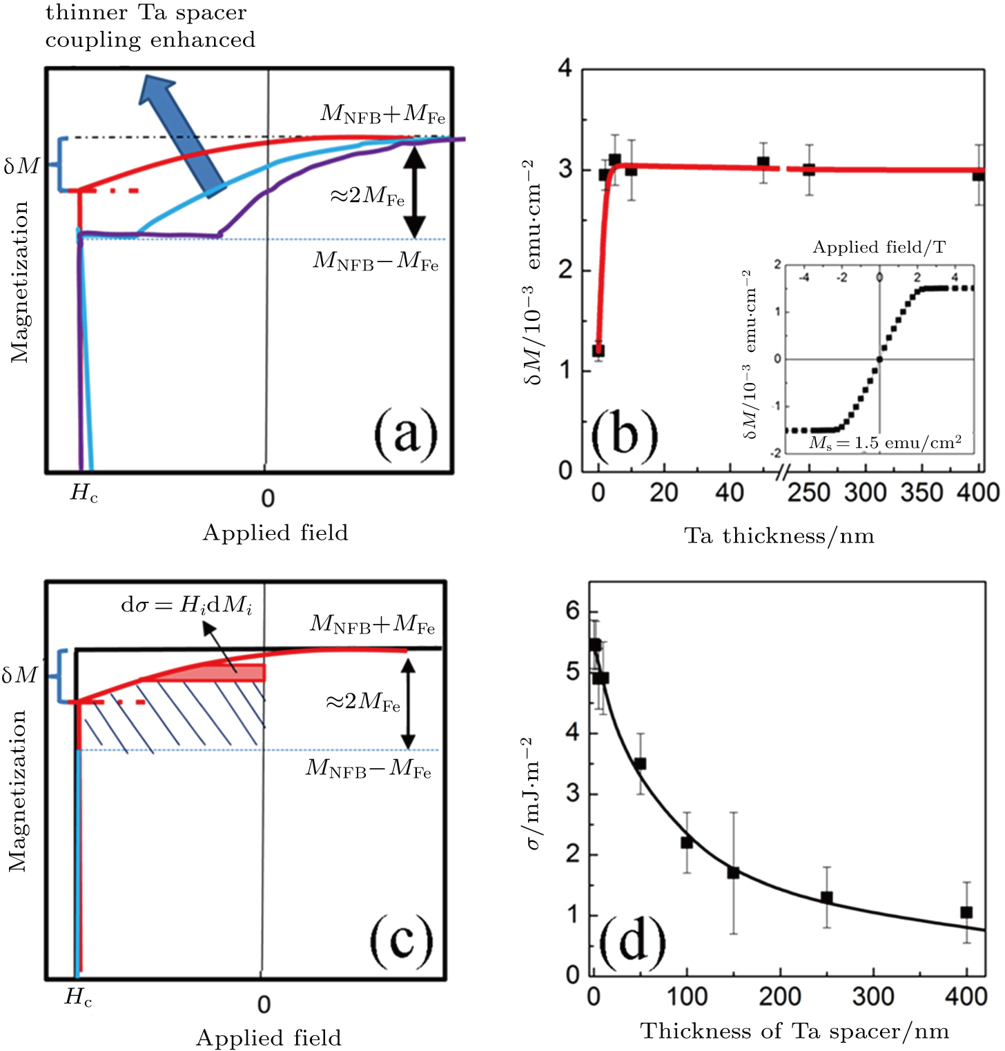 | Fig. 10. (color online) (a) Schematics of the demagnetization process of thin films with different Ta thickness. (b) dM as a function of the thickness of Ta spacer layer in Ti (20 nm)/NdFeB (100 nm)Nd (10 nm)/Ta (x nm)/Fe (10 nm)/Ti (20 nm) films (x = 0–400). The inset shows the magnetization curve for 10 nm of the Fe layer. (c) Schematic of the estimation of coupling energy. (d) Coupling energy r as a function of the thickness of Ta spacer layer along the OOP direction.[25] |
Figure
 | Fig. 11. (color online) (BH)max as a function of the thickness of the Ta spacer layer in Ti (20 nm)/NdFeB (100 nm)Nd (10 nm)/Ta (x nm)/Fe (10 nm)/Ti (20 nm) films (x = 0–50) and the thickness of Fe layer in Ti (20 nm)/NdFeB (100 nm)Nd (10 nm)/Ta (2 nm)/Fe (y nm)/Ti (20 nm) films (y = 0–20). The dashed line stands for the (BH)max benchmark of SLTi (20 nm)/NdFeB (100 nm)Nd (10 nm)/Ti (20 nm) thin film.[25] |
From the results mentioned above, it can be concluded that the interactions between soft- and hard-magnetic layers can still work well over a very long distance, which is several times larger than the Rudermann–Kittel–Kasuya–Yosida (RKKY) type of interaction reported in Fe/Cr/Fe multilayer film[27–29] and the Heisenberg exchange interaction. This kind of long-range interaction is a good supplementary for the exchange-coupling model of nanocomposite magnets.[3,30] Thus, it is very important to make clear the mechanism of the long-range interactions between the hard- and soft-magnetic layers. Dai et al.[31] analyzed the interactions mechanism by using the first-order-reversal-curves (FORCs) distributions and discussed the dependence of the mean interaction on the distance between soft- and hard-magnetic layers.
The room-temperature in-plane (IP) and out-of-plane (OOP) hysteresis loops of Nd–Dy–Fe–Co–B (150 nm)/MgO (tMgO)/Fe (10 nm) (tMgO = 0 nm, 2 nm, 60 nm, 70 nm, and 100 nm) multilayers are shown in Fig.
 | Fig. 12. (color online) The room temperature in-plane (IP) and out-of-plane (OOP) hysteresis loops of Nd–Dy–Fe–Co–B (150 nm)/MgO (tMgO)/Fe (10 nm) (tMgO = 0 nm, 2 nm, 60 nm, 70 nm, and 100 nm).[31] |
The OOP demagnetization curves of multilayers with Ta and Cr2O3 spacer layers are presented in Figs.
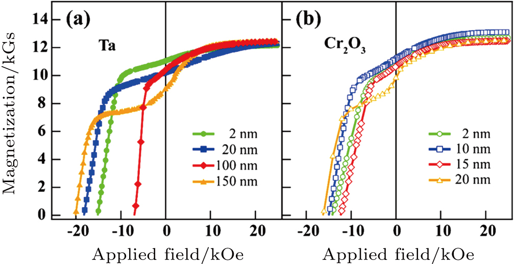 | Fig. 13. (color online) OOP demagnetization curves of Nd–Dy–Fe–Co–B (100 nm)/S/Fe (10 nm). (a) The thicknesses of the Ta spacer layers are 2 nm, 20 nm, 100 nm, 150 nm and (b) the thicknesses of the Cr2O3 spacer layers are 2 nm, 10 nm, 15 nm, 20 nm.[31] |
To understand the nature of long-range interactions in anisotropic nanocomposite multilayers, FORC diagrams are made. The FORC distributions are thought to be highly sensitive to the interacting particles and have been widely used on nanocomposite magnets.[34–37] It was initially proposed as a method to identify the Preisach model parameters and was later extended as a model-independent technique to characterized the hysteresis in the magnetization reversals of the magnetic materials.[38,39] Subsequently, it has been proven to be a useful technique to model the behavior of hysteretic materials, including the determination of interactions in multiphase magnetic systems.[40] The acquisition of a FORC begins by saturating the system in a positive applied field. Then the applied field is decreased to a reversal field Hr, and the magnetization M is measured starting from Hr back to positive saturation.[41,42] The magnetization on a FORC curve at an applied field Ha for a reversal field Hr is denoted by M(Ha, Hr), where Ha ≥ Hr. A FORC distribution is defined as[43,44]
A number of color lines filling the interior of the major hysteresis loops of the Nd–Dy–Fe–Co–B single layer and the Nd–Dy–Fe–Co–B (100 nm)/Ta (2 nm)/Fe (10 nm) multilayer are shown in Figs.
 | Fig. 14. (color online) (a) Color lines: first-order reversal curves for single-layer Nd–Dy–Fe–Co–B. Color contour plots: M and Hr dependence of the FORC function distribution; (b) the main analysis data: color contour plots of the Hc and Hb dependence of FORC function distribution. (c) Color lines: first-order reversal curves for Nd–Dy–Fe–Co–B (100 nm)/Ta (2 nm)/Fe (10 nm) multilayer. Color contour plots: M and Hr dependence of the FORC function distribution; (d) the main analysis data for Nd–Dy–Fe–Co–B (100 nm)/Ta (2 nm)/Fe (10 nm) multilayer: color contour plots of the Hc and Hb dependence of FORC function distribution. The color scale represents the distribution of the values of ρ.[31] |
Combining the characteristics of the hysterons and the FORC distribution function,[40] the FORC diagrams of the multilayer system with a mean interaction field were obtained in Figs.
 | Fig. 15. (color online) Contour plot images converted from FORCs for (a) Nd–Dy–Fe–Co–B, (b) Nd–Dy–Fe–Co–B/Fe, (c) Nd–Dy–Fe–Co–B/Ta (2 nm)/Fe, (d) Nd–Dy–Fe–Co–B/Ta (100 nm)/Fe, and (e) Nd–Dy–Fe–Co–B/Ta (150 nm). Extracted (f) irreversible and (g) reversible distributions, which correspond to the samples in panels (a)–(e).[31] |
The quantitatively extracted reversible and irreversible components from the FORC diagrams of the Nd–Dy–Fe–Co–B single layer and Nd–Dy–Fe–Co–B (100 nm)/Ta/Fe (10 nm) multilayers are presented in Figs.
Integration of the dM/dHr curves will quantitatively reflect the magnetic entities involved in the reversible or irreversible process. The soft-magnetic part in the magnet contributes mostly to the reversible components, whereas the hard-magnetic part requires the larger fields to rotate the irreversible components. Therefore, the maximum value of the irreversible process is around the coercive field (see Fig.
The exchange-coupling between the hard- and soft-magnetic nanocomposite magnets based on the FORC method has been reported earlier.[34–37] When soft- and hard-magnetic layers are coupled with each other beyond a critical distance, the weak long-range dipolar interaction becomes dominant. According to the results of Cui et al.[25] and Gabay et al.,[47] the dipolar interaction may play an important role in combining the soft- and hard-magnetic phases. To investigate the FORC distribution of a multilayer with insulating spacer layer, the contour plots of the multilayers with MgO (5 nm) and Cr2O3 (5 nm) spacer layer are presented in Figs.
 | Fig. 16. (color online) (a) FORC distributions for Nd–Dy–Fe–Co–B/MgO (5 nm)/Fe in Hb vs. Hc representation. (b) FORC distributions for Nd–Dy–Fe–Co–B/Cr2O3 (5 nm)/Fe in Hb vs. Hc representation.[31] |
Nanocomposite multilayers, which are consist of independent soft- and hard-magnetic layers (SM/HM), present an advantage on controlling the competition of the surface- or interface-induced interactions. Therefore, it is desirable to further study the magnetic interactions via directly observing the domain structures in-field rather than making indirect conclusions.
The room temperature in-plane (IP) and out-of-plane (OOP) hysteresis loops of Nd–Dy–Fe–Co–B single layer, well-coupled and decoupled samples are shown in Figs.
 | Fig. 17. (color online) The room temperature IP and OOP hysteresis loops (a)–(c), families of FORCs (d)–(f), and MFM images in the as-prepared state (g)–(i). For the Nd–Dy–Fe–Co–B single layer (a), (d), and (g), the well-coupled sample (b), (e), and (h), and the decoupled sample (c), (f), and (i), respectively.[48] |
The families of FORCs in the out-of-plane direction of the films are shown in Figs.
The as-prepared state is almost a virgin state (thermal demagnetized). The MFM images of the Nd–Dy–Fe–Co–B single layer and the well-coupled and decoupled multilayer films are shown in Figs.
In order to understand the behavior of domains under a specific field, the applied magnetic field was applied perpendicular to the film during the measurement of the MFM images. In Figs.
 | Fig. 18. (color online) MFM images of the well-coupled sample. The AFM topography (a) and the MFM images scanned at 1 T (b), 0.1 T (c), −0.1 T (d), −0.5 T (e), −1 T (f), −1.5 T (g), −1.7 T (h), and −3 T (i). All MFM images are taken from the same area.[48] |
Compared with the results on the well-coupled sample, the behavior of the decoupled sample can be divided into two separated nucleation processes. The first nucleation process begins before the applied field is decreased to 1.2 T. In Figs.
 | Fig. 19. (color online) MFM images of the decoupled sample. The AFM topography (a) and the MFM images scanned at 1.2 T (b), 1.1 T (c), −0.1 T (d), −0.7 T (e), −1 T (f), −1.3 T (g), −1.5 T (h), and −2.5 T (i). All MFM images are taken from the same area.[48] |
In a simplistic consideration, the domain pattern reflects the competition of dipolar magnetostatic energy, Zeeman energy, and domain wall energy. Based on the micromagnetic theory,[54,55] the ferromagnetic multilayers with perpendicular magnetic anisotropy (PMA) always present stripe domains. By assuming the stripe period D = dup + ddown and dimensionless parameter q = (dup − ddown)/D, where dup and ddown are up and down domain widths, the energy density of a stripe domain can be written in the following form:[56,57]

It should be noted that without the HM layer, the magnetization of SM thin film is aligned in-plane and there should be no stray field detected by MFM technology. But in both the well-coupled and decoupled nanocomposite multilayers, the out-of-plane magnetization is shown at the surface of the SM layer. It is concluded that although the domains of SM layer are not aligned parallel with the coherent HM layers in decoupled multilayer, a small angle between the moments of SM and HM layers is performed due to the existence of the weak dipolar interactions between SM and HM layers. Therefore, the magnetization of the SM layer contributes to the domains along out of plane.
To investigate the magnetization reversal behavior between adjacent layers, the patterned micron-size disk arrays were prepared. The lithography-patterned arrays of soft Fe disks onto continuous Nd–Dy–Fe–Co–B hard-magnetic layer are shown in Fig.
 | Fig. 20. (color online) The MFM images of the micron-size SM disk. (a) Schematic illustration of lithography-patterned arrays of soft Fe disks onto continuous Nd–Dy–Fe–Co–B hard-magnetic layer, and the well-coupled and decoupled structures are tuned by inserting a critical thickness of spacer layer. (b) Optical image of the disks array prepared by lithography technology. (c) and (d) The in-field MFM images of the well-coupled and decoupled disks, respectively. (e) and (f) Line profiles extracted from MFM images shown in panels (c) and (d), respectively.[48] |
It is concluded that a strong dipolar interaction between SM and HM layers favors smaller domains. Micron-sized nanocomposite structures consisting of the soft Fe disks and the continuous Nd–Dy–Fe–Co–B film are manipulated by lithography. The Fe disks coupled with the Nd–Dy–Fe–Co–B exhibit a coherent magnetization reversal. While the decoupled disk magnetization of SM/HM layers is independent and nucleation initially starts from the Nd–Dy–Fe–Co–B layer at negative descending field. Furthermore, it is found that a strong anisotropy of the Nd–Dy–Fe–Co–B layer decreases the interaction length. These results provide a microscopic understanding of magnetization reversal in the long-ranged dipolar interactions between soft- and hard-magnetic phases.
In summary, the coherent switching process of the hard- and soft-magnetic phases has been presented by altering the thickness of different kinds of spacer layers. However, an antiferromagnetic spacer layer may weaken the interaction between the ferromagnetic layers and the effective interaction length is decreased. In addition, the ratios of the irreversible component dependent on the thickness of the spacer layer illustrate that the shape anisotropy is important in the long-range interactions in a soft- and hard-magnetic layer system. The present observations may contribute to a new discussion on understanding the mechanism of long-range soft- and hard-magnetic interactions in anisotropic nanocomposite magnets.
3. Anisotropic SmCo5 based nanocomposite permanent multilayer magnets
The SmCo5 compound possesses huge uniaxial magnetocrystalline anisotropy (Ku ≈ 17.2 MJ/m3 and anisotropy field (μ0HA ≈ 35 T), so it can generate large coercivity if crystal grains are magnetically isolated in thin films.[59,60] Depending on compositions and preparation conditions, various Sm–Co phases, such as SmCo3, Sm2Co7, SmCo5, SmCo7, and Sm2Co17, which show different anisotropy fields, can be formed. Among them, the SmCo5 phase has the highest anisotropy field. A high coercivity has been achieved by depositing Sm–Co onto a heated substrate[61] or by annealing the film deposited at room temperature.[62–64] In addition, the easy axis (c-axis) of SmCo5-based thin films can be manipulated by using different substrates. The c-axis in-plane (IP) geometry was reported in the films epitaxially grown on MgO (110) single crystal substrates with W[65] and Cr[66] buffer layers. The c-axis out-of plane (OOP) geometry was realized by growing SmCo5 films on Al2O3(001) single-crystal substrates with Ru buffer layers.[67] Since SmCo5 as a hard phase couples with hard phases such as Fe, Co, and FeCo in the multilayer films, the related work has been performed.[68–73] Although the exchange coupling and machanism of coercivity have been investigated in these early reports, the maximum energy product of the exchange coupled films is not high. In this part, we will review recent work on anisotropic SmCo5 based nanocomposite permanent multilayer magnets in which the energy product of the films has been improved obviously.
Zhang et al.[74] selected SmCo5 as a hard phase and Fe as a soft phase. The multilayer films were prepared by sequentially depositing Sm–Co, Cu, and Fe layers on a 100-nm-thick Cr underlayer on a thermally oxidized Si wafer. The structure of the Sm–Co layer was amorphous in the as-deposited condition, so the as-deposited films were Cr (50 nm)/[a-(Sm–Co) (9 nm)/Cu (x nm)/Fe (5 nm)/Cu (x nm)]6/Cr (100 nm)/a-SiO2, where “a” indicates amorphous phase. Then, the films were heat treated at temperatures ranging from 450 °C to 525 °C for 30 min. Figure
 | Fig. 21. (color online) In-plane and out-of-plane hysteresis loops of the film with x = 0.5 annealed at 450 °C for 30 min.[74] |
As a very promising approach, fully epitaxial trilayers based on the hard magnetic SmCo5 phase and soft magnetic Fe have been realized,[75] which possess a unique alignment of the SmCo5’s easy axis throughout the whole layer stack and reach energy densities of 224 kJ/m3 (28 MGOe). In order to enhance the energy density (BH)max as a key property for permanent magnet applications, exchanged-coupled trilayers of SmCo5/Fe/SmCo5 with fixed SmCo5 layer thickness (25 nm) and varying soft magnetic Fe film thickness have been epitaxially grown by pulsed laser deposition on Cr buffered MgO (110) substrates.[76] A real view of the layer architecture is displayed in the TEM bright field cross sectional image of the sample with 12 nm nominal Fe (Fig.
 | Fig. 22. (color online) Transmission electron microscopy cross sectional image of a trilayer with nominal 12 nm Fe along the magnetic easy axis (c-axis).[76] |
A selection of magnetic hysteresis curves measured along the MgO[001] direction is given in Fig.
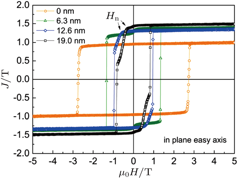 | Fig. 23. (color online) Polarization J as a function of the external field μ0H measured along the MgO[001] orientation (in plane easy axis) for SmCo5 (25 nm)/Fe (x nm)/SmCo5 (25 nm) trilayers with x = 0, 6.3, 12.6, and 19.0.[76] |
The coercive field and the nucleation field as a function of the Fe thickness measured along the easy axis (for all samples) are shown in Fig. 
 | Fig. 24. (color online) Coercive field Hc and nucleation field Hn as a function of the Fe thickness dFe. The dashed line represents the critical point where the change of the single phase to the exchange spring behavior occurs.[76] |
In order to investigate the effects of easy axis orientations on the coercivities and their thermal stabilities, Cui et al.[81] prepared different morphologies and c-axis geometries of Sm(Co0.9Cu0.1)5 (50 nm) single-layer (SL) films and Sm(Co0.9Cu0.1)5/Fe2Co exchange coupled bi-layer films by co-sputtering Sm(99.5%), Co(99.9%), and Cu(99.9%) targets onto Cr (20 nm)-buffered MgO (110) (or Ru (20 nm)-buffered Al2O3(012)) single-crystal substrates respectively. Figure
 | Fig. 25. (color online) Hysteresis loops of MgO/Cr (20 nm)/Sm(Co0.9Cu0.1)5 (50 nm)/Fe2Co (x nm)/Cr (20 nm) films with c-axis in-plane (IP) geometry (x = 3 (a), 5 (b), 8 (c), and 10 (d)) and Al2O3/Ru (20 nm)/Sm(Co0.9Cu0.1)5(50 nm)/Fe2Co (x nm)/Ru (20 nm) films with c-axis out-of-plane (OOP) geometry (x = 3 (e), 5 (f), 8 (g), and 10 (h)).[81] |
To understand the physical mechanism, schematics of different c-axis geometries in exchange coupled bilayer films are plotted in Figs.
 | Fig. 26. (color online) Schematics of c-axis out-of-plane (OOP) (a) and in-plane (IP) (b) exchange coupling (EC) geometries in exchange-coupled bilayer films. (c) Comparisons of exchange coupling energy (Eex) and magnetostatic energy (Estatic) between moment |
Exchange coupling is a short-range interaction because exchange stiffness Aex decays exponentially within several nanometers.[31,82,83] On the other hand, magnetostatic coupling is a long-range interaction due to the integration of every moment in both hard/soft-magnetic layers as seen from Fig.
In summary, the effective critical correlation length (
4. Anisotropic rare-earth free based nanocomposite permanent multilayer magnets
Rare-earth free based permanent magnets such as AlNiCo, ferrite, FePt, MnAlC, and MnBi have been investigated. As a hard phase of anisotropic rare-earth free based nanocomposite permanent multilayer magnets, it is of strong uniaxial anisotropy and can be grown on the substrate along the easy axial direction. So we will only review the anisotropic FePt and MnBi based nanocomposite permanent multilayer magnets in this part.
It is known from the equilibrium phase diagram of the Fe–Pt binary alloy system that for the ordered alloy FePt, it crystallizes in the fct L10 structure with the high magnetocrystalline anisotropy constant K1 (> 1 MJ/m3), but it does not coexist with α-Fe. Liu et al.[85] sputtered Fe layers having twice the thickness of the Pt layers to prepare multilayers with an atomic Fe-to-Pt ratio of about 2:1. To avoid excessive grain growth, a special rapid thermal annealing process that includes more than one step of treatment was adopted. An extremely large energy product corrected by an effective demagnetizing factor in the perpendicular direction was achieved at room temperature, in which the soft phase is Fe3Pt and it belongs to isotropic. Jiang et al.[86] reported that interlayer exchange coupling between FePt and Fe layers through a Ru spacer was obtained with an oscillation period of about 1 nm. Magnetic properties of FePt thin films with different nominal thicknesses deposited on MgO (1 1 0) substrates at 400 °C showed that 12.5 nm thick FePt film had both high coercivity and good squareness. In FePt/Ru/Fe trilayers, ferromagnetic coupling between the two magnetic layers was achieved with a 0.5 nm thick Ru layer, and the saturated magnetization was largely improved after using interlayer exchange coupling with Fe while the coercivity changed little, which indicated that indirect exchange spring was a promising approach for high-performance magnets. However, the exchange coupling strength trailed off with Fe content increasing, and a hysteresis loop with good rectangular in FePt/Ru/Fe trilayers can be obtained when the thickness ratio of FePt/Fe is larger than 6. The hysteresis loops with good rectangular have also been obtained in (FePt/Ru/Fe)10 multilayers even when the thickness ratio of FePt/Fe is 1. Liu et al.[87] reported that two-phase nanostructures of hard L10-ordered FePt and soft iron-rich fcc Fe–Pt are investigated experimentally and by model calculations. The Fe–Pt thin films were produced by epitaxial co-sputtering onto MgO and have a thickness of about 10 nm. They form two-phase dots that cover a large fraction of the surface but are separated from each other. X-ray diffraction and TEM show that the c-axis of the phase FePt is aligned in the direction normal to the film plane. The experimental and theoretical hysteresis loops indicate archetypical exchange coupling, and excellent magnetic properties are obtained. The largest values of coercivity, saturation magnetization, and nominal energy product obtained in the samples studied are 51 kOe, 1287 emu/cc, and 54 MGOe, respectively.
In order to realize anisotropic FePt based nanocomposite permanent multilayer magnets, L1(0)-FePt film with 20 nm was deposited on (001) orientated single crystal MgO substrate with in-situ heating at 830 °C, and then spacer layer Ag and different thickness soft layer with Fe was deposited at room temperature. Figure
 | Fig. 27. (color online) Magnetic hysteresis loops at room temperature for the out of plane MgO (substrate)/FePt (20 nm)/Ag (x nm)/Fe (2 nm)/Ag (2nm) films. |
 | Fig. 28. (color online) X-ray diffraction patterns of MgO (substrate)\FePt (10 nm)\MgO (2 nm)\Fe (2 nm)\MgO (2 nm)\FePt (10 nm)\MgO (5 nm) film deposited at 750 °C. |
 | Fig. 29. (color online) Magnetic hysteresis loops at room temperature of the out of plane MgO (substrate)\FePt (10 nm)\MgO (2 nm)\Fe (2 nm)\MgO (2 nm)\FePt (10 nm)\MgO (5 nm) film deposited at 750 °C. |
The low temperature phase (LTP) of MnBi is a ferromagnetic intermetallic compound which crystallizes in the NiAs-type hexagonal crystal structure.[88–90] LTP MnBi has attracted a great deal of attention due to the unusual magnetic properties, for example, a magnetocrystalline anisotropy (HA) of 9.0 T and a coercivity (HC) of 1.8 T have been achieved for melt-spun ribbons at 550 K,[91] which are much larger than those of the Nd–Fe–B magnet under the same conditions. Hence, LTP MnBi has an exciting prospect as a non-rare-earth permanent magnet material for high temperature applications,[92] and experimental investigations on the effect of Fe impurity on the structural, magnetic and electron transport properties of MnBi films. Kharel et al. reported experimental investigations on the effect of Fe impurity on the structural, magnetic, and electron transport properties of MnBi films.[93] They have found a significant change in the magnetic properties of MnBi films due to Fe substitution. The out-of plane M(H) hysteresis loops are almost rectangular for all the films, but the samples with higher Fe concentrations (≥ 11%) show a signature of mixed phase. Figure
 | Fig. 30. (color online) The out-of-plane magnetization of Mn55−xFexBi45 (x = 0, 4, 8, 13) films as a function of magnetic field measured at room temperature. The inset shows the room temperature M(H) loop of Mn39Fe16Bi45 film.[93] |
In fact, the investigations on the structural and magnetic properties of anisotropic MnBi films have been reported many times, but the exchange coupling on anisotropic MnBi/Fe films has been seldom reported. Figure
 | Fig. 31. (color online) The depth profile by XPS study for MnBi/Fe film.[94] |
Figure
 | Fig. 32. (color online) Out-of-plane hysteresis loops for MnBi/Fe films at 400 K (square) and 300 K (circle). The thickness of Fe layer is (a) 2 nm, (b) 4 nm, (c) 6 nm, and (d) 10 nm, respectively.[94] |
In summary, because the magnetocrystalline anisotropy of the ordered L10FePt phase is higher that of Nd2Fe14B, the effective exchange coupling length is shorter than that of the latter. In addition, the aligned FePt phase is generally formed on MgO substrate or crystalline layer at high temperature, thus, it is not suitable for designing an anisotropic hard/soft multilayer system.
In anisotropic hard/soft magnetic multilayer films, a nonmagnetic spacer layer is inserted in between the textured hard and soft-magnetic phase layers and the exchange-coupling interaction between the hard- and soft-magnetic phases is indirect and long-ranged. Thus, a new way is given to obtain a higher energy product in anisotropic nanocomposite hard/soft magnetic multilayer films. Some studies open a new discussion for comprehending the mechanism of long range soft- and hard-magnetic coupling in the anisotropic nanocomposite magnets. Predictably, if the method can be used in anisotropic nanocomposite magnets of a bulk system, it will play an important role in enhancing the magnetic properties of permanent magnet product in the future.
Reference
| [1] | |
| [2] | |
| [3] | |
| [4] | |
| [5] | |
| [6] | |
| [7] | |
| [8] | |
| [9] | |
| [10] | |
| [11] | |
| [12] | |
| [13] | |
| [14] | |
| [15] | |
| [16] | |
| [17] | |
| [18] | |
| [19] | |
| [20] | |
| [21] | |
| [22] | |
| [23] | |
| [24] | |
| [25] | |
| [26] | |
| [27] | |
| [28] | |
| [29] | |
| [30] | |
| [31] | |
| [32] | |
| [33] | |
| [34] | |
| [35] | |
| [36] | |
| [37] | |
| [38] | |
| [39] | |
| [40] | |
| [41] | |
| [42] | |
| [43] | |
| [44] | |
| [45] | |
| [46] | |
| [47] | |
| [48] | |
| [49] | |
| [50] | |
| [51] | |
| [52] | |
| [53] | |
| [54] | |
| [55] | |
| [56] | |
| [57] | |
| [58] | |
| [59] | |
| [60] | |
| [61] | |
| [62] | |
| [63] | |
| [64] | |
| [65] | |
| [66] | |
| [67] | |
| [68] | |
| [69] | |
| [70] | |
| [71] | |
| [72] | |
| [73] | |
| [74] | |
| [75] | |
| [76] | |
| [77] | |
| [78] | |
| [79] | |
| [80] | |
| [81] | |
| [82] | |
| [83] | |
| [84] | |
| [85] | |
| [86] | |
| [87] | |
| [88] | |
| [89] | |
| [90] | |
| [91] | |
| [92] | |
| [93] | |
| [94] |