Tuning the velocity and flux of a low-velocity intense source of cold atomic beam
Chen Shu1, Li Ying-Ying1, Yan Xue-Shu1, Xue Hong-Bo2, Feng Yan-Ying1, †
State Key Laboratory of Precision Measurement Technology and Instruments, Department of Precision Instruments, Tsinghua University, Beijing 100084, China
State Key Laboratory of Space Weather, National Space Science Center, Chinese Academy of Sciences, Beijing 100190, China


† Corresponding author. E-mail: yyfeng@tsinghua.edu.cn

Project supported by the National Natural Science Foundation of China (Grant Nos. 61473166 and 41404146).

Abstract

We investigate experimentally and numerically the quantitative dependence of characteristics of a low-velocity intensity source (LVIS) of atomic beam on light parameters, especially the polarization of cooling laser along the atomic beam axis (pushing beam). By changing the polarization of the pushing beam, the longitudinal mean velocity of a rubidium atomic beam can be tuned continuously from 10 to 20 m/s and the flux can range from 3 × 10⁸ to 1 × 10⁹ atoms/s, corresponding to the maximum sensitivity of the velocity with respect to the polarization angle of 20 (m/s)/rad and the mean sensitivity of flux of 1.2 × 10⁹ (atoms/s)/rad. The mechanism is explained with a Monte-Carlo based numerical simulation method, which shows a qualitative agreement with the experimental result. This is also a demonstration of a method enabling the fast and continuous modulation of a low-velocity intense source of cold atomic beam on the velocity or flux, which can be used in many fields, like the development of a cold atomic beam interferometer and atom lithography.

1. Introduction

Since the first demonstration of a laser-cooled atomic beam by Phillips and Metcalf,[1] a bright and cold atom beam has become the basis of many precise measurements and atom optic experiments, including ultra-high-resolution atomic and molecular spectroscopy,[2,3] atom frequency standards,[4,5] Bose–Einstein condensation (BEC) experiments,[6,7] atom interferometers,[812] atom lithography,[13] etc. The desirable features for a cold beam of neutral atoms are high flux at low average velocity, small divergence, tunability of flux and velocity, and robustness and stability in the beam parameters, which are especially important in our case, where a cold atomic beam of rubidium is directly used as a matter wave source for an atom interferometer.[14]

For obtaining a high-flux low-velocity atomic beam, two classes can be generally identified among the different schemes developed. One of the earliest methods is to start with a thermal beam and decelerate it along its propagation axis using radiation pressure in several methods, such as Zeeman slower,[1,15,16] frequency-chirped laser radiation,[15,17,18] isotropic light slowing,[19] and wideband light slowing.[4,20] Among these methods, Zeeman slowers are still widely used to give a high flux of atoms (about 1011 − 1012 atoms/s). However, the process of cooling by all these techniques is accompanied by associated photon heating, which induce unavoidable increase in the transverse temperature of atoms and hence a decrease in the beam brightness and phase space density.

The other class of methods more recently adopted is to use magneto-optic forces to first confine atoms in a vapor cell, which form a reservoir from which atoms can be efficiently ejected into a well-collimated beam. Vapor cells trade-off flux (about 109 − 1010 atoms/s) for the transverse compression of the atomic beam, a decrease in the longitudinal velocity of atoms and a reduced background of thermal atoms, but with similar flux density and a greater flexibility in design. The three most common vapor cell designs have been developed according to different configurations of magnetic and optical fields, including two-dimensional (2D) MOT,[9,2125] 2D+ MOT[2633] and its variations,[3439] and 3D MOT or the LVIS.[4043] Both the 2D+ MOT and LVIS designs use cooling and radiation force imbalance along the flux axis to produce a slow and narrow velocity distribution to several meters per second range, using a 2D and 3D quadrupole magnetic field, respectively. In the cases of the 2D MOT and 2D+ MOT design, the standard three-dimensional (3D) MOT arrangement in the source chamber is replaced by a 2D MOT configuration, with (2D+ MOT) or without (2D MOT) push and cooling beam along the symmetry axis. These techniques have been used for generating cold beams of different species of atoms and molecules from alkaline atoms (Li, Na, K, Rb, Cs) to the alkaline earths,[44] metastable helium,[45] and NH3 molecular.[46]

The choice of the method for producing a cold atomic beam depends on the specific requirements of the subsequent experiment. Most of these continuous cold atomic beam are eminently suitable for loading MOT, but are still very far from the ideal of a continuous beam with a controllable velocity, density, and temperature in the moving frame comparable to a pulsed cold atomic source based on an MOT in the application of an atom interferometer experiment. On one hand, flexible velocity or flux tunability is important for getting precise control or modulation on parameters of a matter-wave source for a well-defined de Broglie wavelength. On the other hand, these factors may lead to the instability of beam parameters of an atomic source, which induces phase noise of an atom interferometer. Several methods have been demonstrated for controlling the flux of an atomic beam and correspondingly the longitudinal velocity by changing the detuning of the cooling beam,[47,48] using separate “pushing” and “retarding” beams along the flux axis,[27] or two-color pushing beams.[36]

In this paper, we study the characteristics of an LVIS atom beam as a function of light beam parameters, especially the pushing light polarization. A 87Rb atomic beam is prepared and experimentally measured for this aim and a numerical simulation based on the Monte Carlo method is used to explain our results qualitatively. Results show that pushing beam polarization angle may influence the longitudinal velocity and flux of an LVIS atomic beam with the sensitivity of 20 (m/s)/rad and 1.2 × 10⁹ (atoms/s)/rad, respectively. This also presents a simple method which enables fast modulation of an LVIS atomic beam on the longitudinal mean velocity ranging continuously from 10 to 20 m/s by changing the polarization of the pushing beam.

2. Experimental setup

A diagram of the experimental setup is shown in Fig. 1. The vacuum system consists of two chambers, each of which is pumped with a single ion pump. One chamber, working for an imbalanced three-dimensional (3D) magneto-optical trap (MOT), is pumped to 2 × 10⁻⁹ Torr, and the other chamber, working for the subsequent experiments, is pumped to 8 × 10⁻¹⁰ Torr when the rubidium reservoir is turned off. The two chambers are separated by a λ/4 plate and a mirror, denoted as QWP1 and M1, respectively, each of which has a hole of diameter 1.5 mm at its center (Fig. 1). An LVIS of cold 87Rb atoms is generated from the first chamber in which cold atoms are prepared in a vapor-cell 3D MOT.[40] Standard 3D MOT optics with the retro-reflective configuration are implemented with the cooling light tuned to the 87Rb 5s2S1/2, F = 2 → 5p2 P3/2, F′ = 3 allowed transition with a typical red detuning of δ = 4–5Γ (where Γ = 2 π × 6 MHz is the natural linewidth of 87Rb) and the repumping light tuned to the 5s2S1/2, F = 1 → 5p2P3/2, F′ = 2 allowed transition. The total power of cooling beams is 150 mW with each pair of 45 mm waist beam corresponding to 4.5 mW/cm2 peak intensity. The repumping light of 12 mW total power is overlapped with transverse cooling beams. To trap the atoms, a pair of anti-Helmholtz coils oriented along the z-axis is used to generate a quadrupole magnetic field with a transverse field gradient of about 15 G/cm. Using the holes drilled in QWP1 and M1, one pair of cooling beams, here denoted as pushing beam, is produced along the z-axis by retro-reflection of the light beam. This generates a dark channel along the z-axis and allows cold atoms to leak out continuously from the MOT chamber because of the unbalanced radiation pressure. The continuous cold atomic beam then enters the next chamber with no further cooling or collimation.

Fig. 1. (color online) (a) Schematic of the experimental layout for the LVIS system of 87Rb atoms. M: mirror; HWP: half-wave plate; QWP: quarter-wave plate; PMT: photomultipliers. (b) Level diagram for the ground states |1 ⟩ and |2⟩ and the excited state |e⟩. The frequencies ω1 and ω2 are used to induce Raman transitions between the two ground states.

The longitudinal velocity and flux of the cold atomic beam are measured by the time-of-flight (TOF) method, realized by switching off the atomic beam using a plug beam. The fluorescence of atoms, induced by a probe laser beam, is collected by a photomultiplier tube (PMT, H7422-50, Hamamatsu, Japan) in a distance of 0.7 m from the plug beam. Both the plug beam and probe beam are tuned to the F = 2 → F′ = 3 resonance.

The transverse velocity distribution of the cold atomic beam is measured by the two-photon velocity-selective Raman transitions.[49] When a pair of counter-propagation Raman beams, in Doppler-insensitive geometries, meet at right angle with the atomic beam, the detuning frequency of Raman beam, δD, is related to the transverse velocity vx, where keff = k1k2 is the effective wave vector, ki = ωi/c, i = 1,2 is the wave vector of Raman beams, ωi, i = 1,2 the angular frequency of Raman beams, and c the velocity of light. By sweeping the detuning frequency δD and getting spectrum of the stimulated Raman transition, we can make measurements of transverse velocity distribution of the atomic beam from Eq. (1).

As shown in Fig. 1, the Raman beam 1 with crossed linear polarization is converted into opposite circular polarizations using a quarter-wave plate (QWP3). After passing through the atomic beam, the light fields are linearized by another quarter-wave plate (QWP4), and ω1 and ω2 are spatially separated by a polarizing beam splitter (PBS). Only the ω1 beam is retro-reflected back through the atomic beam. The counter-propagating Raman laser beams are generated for Doppler-sensitive Raman transitions in the form of σ+σ+ or σσ transitions. Removing the QWP3 and blocking the retro-reflected beam allows Raman transitions in Doppler-insensitive geometries, which forms a Raman–Ramsey interferometer along with the Raman beam 2.[50] Raman beams are generated based on a sideband injection-locking technique using a fiber electro-optical modulator (FEOM).[51] To detect the signals of the stimulated Raman transitions and the Raman–Ramsey fringes, Raman detuning is adjusted by sweeping the RF signal driving the Raman optics.

Before interacting with the Raman beams, the atoms initiated in the F = 2 ground state need to be state-prepared to the magnetically insensitive |F = 1, mF = 0⟩ ground state by a combination of optical pumping beams 1 and 2, which are tuned to F = 2 → F′ = 2 allowed transition and F = 1 → F′ = 0 in σ± transitions (linear polarization orthogonal to the magnetic field), respectively. In addition, a constant magnetic bias field is applied throughout the length of the second chamber to define a quantization axis, horizontally in the direction of the Raman beams, with a four-conductor magnetic field assembly running inside the vacuum chamber (not shown in Fig. 1).

3. Numerical simulation

A numerical simulation based on the Monte Carlo method is carried out to model the atomic beam characteristics in a similar approach used by Chaudhuri et al.[33] The simulation considers motion equations of atoms, which are captured from the background vapor in a 3D MOT, form into a beam under the imbalanced radiation pressure, and then pass through a hole into the next UHV chamber where the beam flux is measured.

For the description of motion of atoms in an MOT, we consider the scattering force on atoms in the low-intensity limit. The total scattering force on an atom is given by , where where Γ is the natural linewidth of atomic transition and ħk the momentum of photons. s = I/Isat is the on-resonance saturation parameter for the cooling laser, where I is the laser beam intensity and Isat is the saturation intensity for the atomic transition (Isat for the D2 resonance line in Rb is 1.6 mW/cm2).

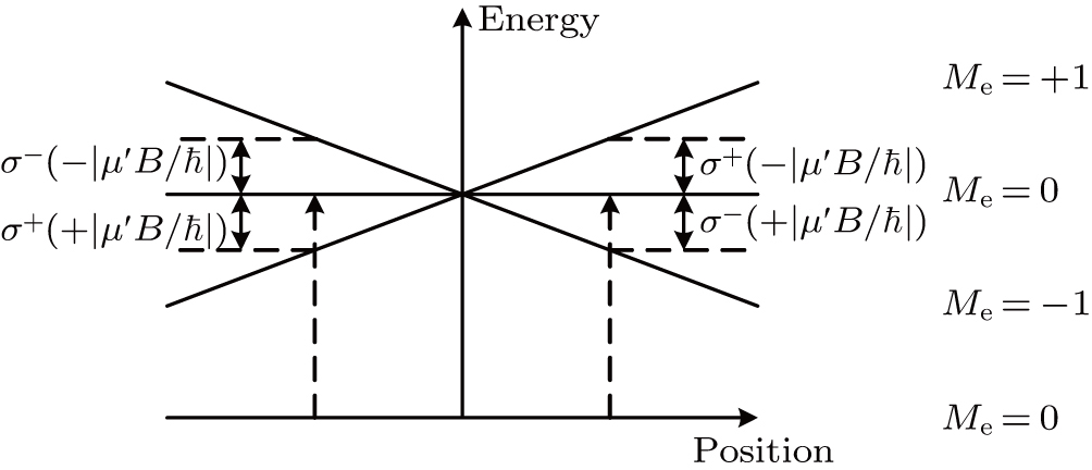
The frequency detuning from resonance, δ±, for each laser beam is given by where δ0 is the laser frequency detuning from resonance, v the velocity of atoms, and the magnitude of local magnetic field produced by the anti-Helmholtz coils. μ′ ≡ (ge meggmg)μB is the effective magnetic moment for the transition used, subscripts g and e refer to ground and excited states, respectively, gg,e is the Lande g factor, μB is the Bohr magneton, and mg,e is the magnetic quantum number. The third term of Eq. (2), + μ′B/ħ is caused by the Zeeman effect. Figure 2 shows δ2 corresponding to +|μB/ħ| for z < 0 and δ to +|μ′B/ħ| for z > 0.

Fig. 2. Arrangement for the LVIS along the cold atom beam. The horizontal axis represents the laser frequency seen by an atom at rest in the center of the trap. The pushing beam and its retro-reflected beam are elliptical, and it can also be seen as the composition of σ+ and σ transition. Both of the cooling beams along the cold atomic beam can work with both of the Me = + 1 and Me = −1.

Equation (2) is based on a pure σ+σ transition, which corresponds to right circularly polarized pushing beam. When rotating the λ/4 wave plate denoted as QWP2 in Fig. 1, the polarization of the pushing beam can be changed to be elliptical. Considering the x linearly polarized wave of initial Jones vector with expansions in linearly polarized basis , the final Jones vector of the light wave J after passing through the λ/4 wave plate with its fast axis along an arbitrary direction at an angle θ′ with the x axis given with expansions in circularly polarized basis: where AR and AL are right and left circularly polarized components, respectively. Thus, the intensity component of the right circularly polarized light IR with respect to the total intensity I of the light is given by where θθ′ − π/4. θ = 0 corresponds to right circularly polarized light which means pure σ+ transition in our case. Combining Eq. (2) with Eq. (5) and ignoring the influence of σσ+ transition pairs, the scattering force along the longitudinal axis becomes Eq. (5)

Equation (6) is the basis for numerical simulation of the LVIS source. Initial positions of atoms are chosen randomly from the 3D cooling chamber. Initial velocities are chosen according to the Maxwell–Boltzmann distribution at 300 K using the Monte Carlo method. Trajectories of atoms are numerically simulated in the presence of velocity-dependent forces imparted by four transverse cooling laser beams and a pair of longitudinal cooling beams with a dark column along the atomic beam axis, and position-dependent forces induced by a quadrupole magnetic field produced by anti-Helmholtz coils. All laser beams are chosen to have Gaussian intensity profiles truncated to the size of AR-coated windows of the chamber along with appropriate polarizations and directions for magneto-optical trapping. We ignore the heating due to spontaneous emission and dipole forces on atoms since these effects on atomic motions are much smaller than radiation pressure forces. Collisional losses due to collisions with background rubidium atoms and cold collisions between atoms in the cold atomic beam are also ignored. When moving into the dark column region, an atom is acted by transverse cooling light beams and only the pushing light beam in the +z direction, which creates a radiation imbalance in that region.

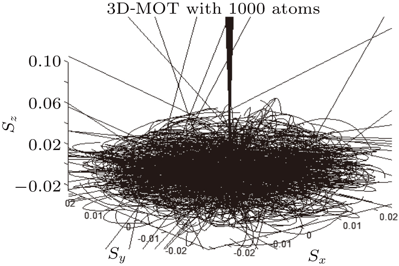
Starting with an initial sample of 1 × 10⁷ atoms, we compute their individual trajectories and obtain the fraction of atoms being captured and transferred into the atomic beam. Trajectories of 1000 atoms calculated by a 3D numerical simulation are shown in Fig. 3. To calculate the atomic beam flux, the initial atom number are scaled up according to the rubidium vapor pressure in the 3D cooling chamber.

Fig. 3. Simulated trajectories of 1000 atoms captured in the vapor cell 3D MOT and transferred to an atomic beam (length in meters).
4. Results and discussion

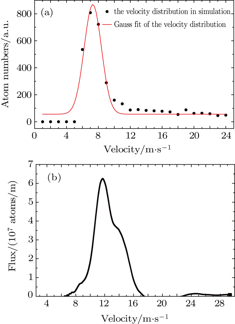
We simulate numerically and measure experimentally various beam characteristics of atoms, especially the atomic beam flux and longitudinal velocity as functions of the cooling beam detuning or the pushing beam polarization. One simulated velocity distribution of an atomic beam extracted from the LVIS and the corresponding experimental result are shown in Fig. 4. The simulated mean longitudinal velocity is 7.3 m/s with a distribution of 3 m/s in full width at half maximum (FWHM), compared to the experimental mean longitudinal velocity of 12 m/s with an FWHM of 3.5 m/s. Generally, atom numbers with low longitudinal velocity in the experiments will be underestimated compared to those in the simulation because atoms with low longitudinal velocity tend to fall down under the action of gravity before they reach the detection region at a distance of 0.7 m from the ejection hole and have not been counted in the experiment. Therefore, the longitudinal velocity distribution in the simulation will totally move towards the lower side compared to that in the experiment under the same conditions. Numerical results show a qualitative agreement with experimental results, but are helpful to understand the mechanism for tuning the beam characteristics.

Fig. 4. (color online) (a) Numerical result of the longitudinal velocity distribution of an atomic beam, the mean velocity is 7.3 m/s with an FWHM of 3 m/s. (b) The corresponding experimental result, and the mean velocity is 12 m/s with an FWHM of 3.5 m/s.

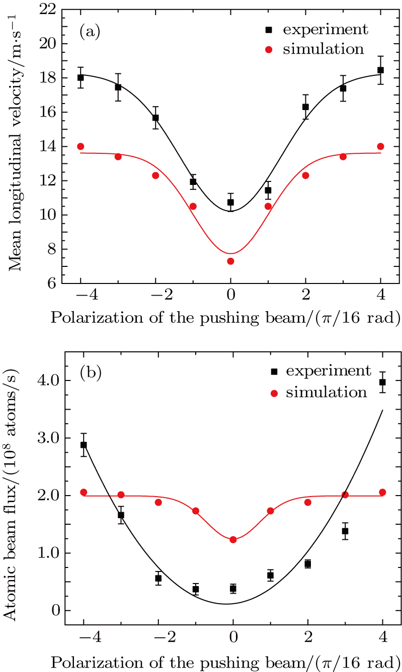
Atomic beam characteristics generated in the LVIS are studied with respect to variation of the pushing beam polarization by rotating the quarter-wave plate QWP2. Experimental and simulation results are shown in Fig. 5. Here, the zero polarization angle of the pushing beam is corresponding to a pure σ+ transition. Data are measured and numerically calculated when QWP2 is rotated every π/16 rad within the range of ± π/4 rad. The mean longitudinal velocity of the atomic beam is sensitive to the variation of polarization of the pushing beam both in experiments and simulations. The maximum sensitivity of the mean longitudinal velocity with respect to the polarization angle can be up to 20 (m/s)/rad. However, the corresponding simulated atomic beam flux show a weaker dependence on the polarization of the push beam with a mean sensitivity of 8.3 × 10⁷ (atoms/s)/rad, compared to the experimental results with a mean sensitivity of 1.2 × 10⁹ (atoms/s)/rad. This can be explained by considering the influence of gravity when low-velocity atoms fly through a long distance and fall down before they reached the detection region and hence cannot be measured in the experiments. Experimental and numerical results show that changing the push beam polarization can be an effective method to tune the velocity and flux of an LVIS atomic beam source.

Fig. 5. (color online) Experimental and simulation data showing the dependence of atomic beam characteristics on polarization of the pushing beam. (a) Mean longitudinal velocity versus polarization of the pushing beam. (b) Atomic flux versus polarization of the pushing beam. The black rectangles are the experimental results and the red circles the numerical results. The horizontal axis represents the polarization angle of the pushing beam in the unit of π/16 rad and with the zero angle corresponding to a pure σ+ transition.

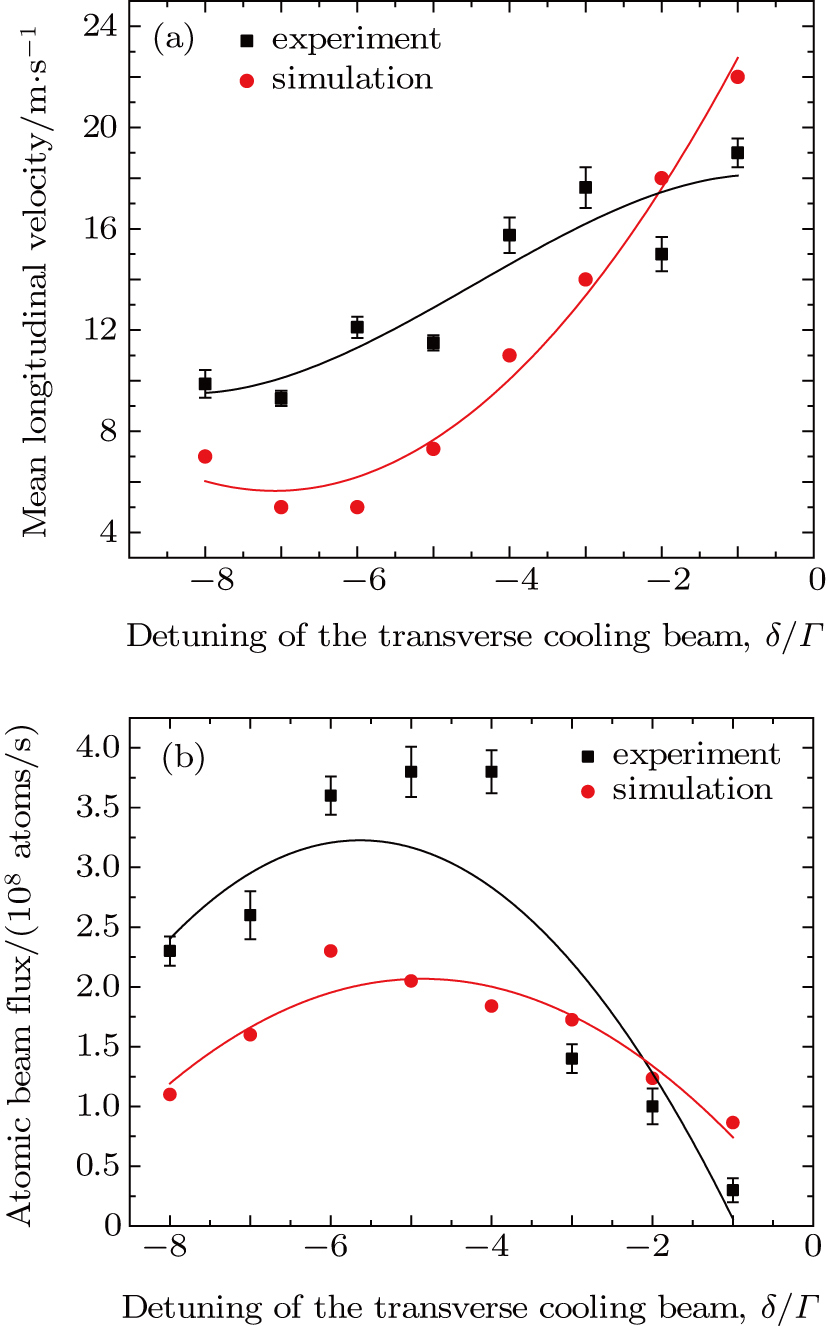
The variation of atomic beam characteristics is also studied as a function of frequency detuning of the transverse cooling laser. Experimental and numerical data are shown in Fig. 6. The change in the mean longitudinal velocity is about 1.1 m/s when the transverse cooling detuning is changed by 1Γ, as shown in Fig. 6(a), and the corresponding atomic beam flux is changed and has the maximum flux when the detuning is −4Γ. Although changing the frequency detuning of transverse cooling beams is also an effective method for tuning the velocity and flux of the LVIS beam,[47] but in some cases it is not convenient to adjust the frequency of a cooling beam without the power fluctuation of the cooling beam, for example when using a single pass AOM for tuning the light frequency.

Fig. 6. (color online) Experimental and simulation data showing the dependence of atomic beam characteristics on the transverse cooling beams detuning. (a) Mean longitudinal velocity versus detuning. (b) Atomic beam flux versus detuning. The black rectangles and red circles are the experimental and numerical results respectively. The horizontal axis represents the frequency detuning of the transverse cooling laser in the unit of the dimensionless parameter δ/Γ, referred to the natural linewidth of the 87Rb atomic transition.

Transverse velocity spread is measured by the Doppler-sensitive Raman transition spectrum. The Doppler-sensitive Raman transition spectra driven by the first π/2 Raman pulse by blocking the Raman beam 2 shown in Fig. 1. The velocity-sensitive Raman transition spectrum is shown in Fig. 7. The transverse velocity spread of the atomic beam is approximately ± 6.5 cm/s (FWHM), which can be estimated from Eq. (1) with the ∼ 336 kHz linewidth of velocity-sensitive Raman transition. This corresponds to the transverse temperature of 177 μK (Doppler cooling limit is 142 μK and 11.8 cm/s for 87Rb atoms) and the divergence of 8.6 mrad. Here the longitudinal velocity of the atomic beam is vz0 = 15.0 m/s and the longitudinal velocity spread is δvz = 3.5 m/s. Doppler-insensitive Raman transitions are driven by residual co-propagating Raman lasers, and are shifted from the peaks by tilting the Raman beams from the orthogonal propagation.
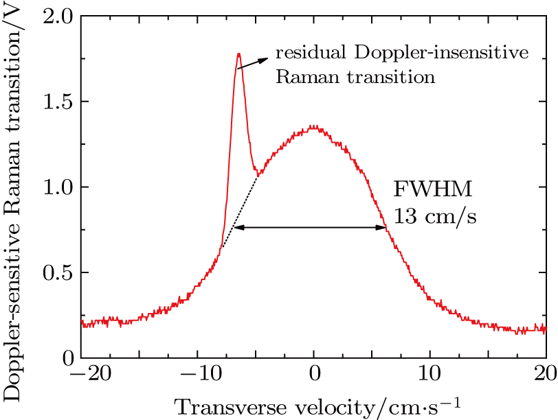
Fig. 7. (color online) Doppler-sensitive Raman transition spectrum for measuring transverse velocity spread.

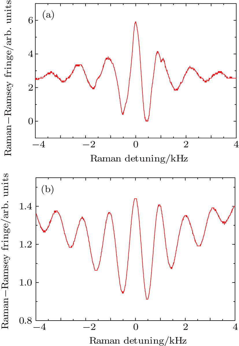
The tunability of the velocity and flux of a continuous LVIS atomic beam are demonstrated in a Raman–Ramsey atomic interferometer by changing the polarization of the pushing beam. With the π/2–π/2 pulse sequence, we obtain the Raman–Ramsey fringes with an interaction-zone separation of L = 19 mm and an interaction-zone width of d = 1 mm. The Raman–Ramsey fringes with different longitudinal velocity of the atomic beam are shown in Fig. 8. As shown in Fig. 8(a), the linewidth of the central fringe is δRamsey = vp/(2L) = 395 Hz, corresponding to an interrogation time of 1.3 ms, where the longitudinal mean velocity is 15 m/s. The fourth order of the interference fringe, where n = vpv = 4, can be clearly identified against the velocity averaging effect.[52] As shown in Fig. 8(b), the Ramsey fringes with a linewidth of 500 Hz (FWHM) for the central fringe is observed when the longitudinal mean velocity of the cold atomic beam is adjusted to vp = 19 m/s. Correspondingly, the free evolution time of the cold atomic beam is T = 1.0 ms.

Fig. 8. (color online) (a) Raman–Ramsey fringes with a linewidth of 395 Hz (FWHM) for the central fringe and corresponding free evolution time of 1.3 m/s when the longitudinal mean velocity of the cold atomic beam is 15 m/s. (b) The Raman–Ramsey fringes with a linewidth of 500 Hz (FWHM) for the central fringe and corresponding free evolution time of 1.0 m/s when the longitudinal mean velocity of the cold atomic beam is 19 m/s.
5. Conclusion

In conclusion, we study experimentally and numerically the quantitative dependence of an LVIS of atomic beam on the polarization of the pushing light beam. Results show that the pushing light polarization is an important factor to influence the flux and velocity of an LVIS atomic beam, with maximum sensitivity with respect to the polarization angle of 1.2 × 10⁹ (atoms/s)/rad and 20 (m/s)/rad, respectively. For an atom interferometer rotating at an angular velocity Ω, the phase shift can be written as ΔΦΩ = keff·[(2v × Ω)T2], where v and T are the initial velocity of atoms and interference time, respectively. The scale factor and its stability of an atom interferometer gyroscope are dependent on the initial velocity of atoms and its stability, respectively. For an atom interferometer gyroscope based on an LVIS of atomic beam, the pushing light polarization instability can contribute a lot to the phase noise of the interferometer and active stabilization on it should be implemented. Take for example an atomic beam interferometer gyroscope using two-photon Raman transition for coherent manipulation of the matter-wave packet, the shot-noise-limited rotation sensitivity ΔΩ near zero rotation rate Ω = 0 can be given[53] as , where v is the mean longitudinal velocity, η the contrast of the interferometer signal, N the number of atoms contributing to the interferometer signal, L = vT the interferometer length. For a typical cold atomic beam interferometer gyroscope (taking N = 1 × 10⁸ atoms/s, η = 50%, L = 0.3 m, v = 20 m/s, keff = 1.6 × 10⁷ m−1 for 87Rb atoms), the shot-noise-limited sensitivity of rotation is 1.95 × 10⁻⁹ rad/s/ and the fluctuation of sensitivity due to the velocity variation of each 10% or the flux variation of each 10% can be calculated to 1.95 × 10⁻¹⁰ rad/s/ or 9.8 × 10⁻¹¹ rad/s/ , respectively.

Although we have demonstrated that the pushing beam polarization is one of the important factors that influence the characteristics of an LVIS of an atomic beam, the improvement of the stability of an LVIS of atomic beam depends on the systematic optimization involving many experimental parameters like light intensity, frequency detuning, etc. Concerned with the pushing beam polarization, one can make the LVIS source operate in the polarization-insensitive range or take some active method for stabilizing the polarization. On the other hand, one can fast tune the velocity and flux of an LVIS-based atomic beam by simply changing the polarization of the pushing light for actively stabilizing the atomic beam source or amplitude modulating and demodulating the phase of an atomic beam interferometer to get interferometer signal with higher signal-to-noise ratio.

Reference
[1] Phillips W D Metcalf H 1982 Phys. Rev. Lett. 48 596
[2] Wineland D J Itano W M Bergquist J C Hulet R G 1987 Phys. Rev. 36 2220
[3] Gtz S Hltkemeier B Hofmann C S Litsch D DePaola B D Weidemller M 2012 Rev. Sci. Instrum. 83 073112 http://rsi.aip.org/resource/1/rsinak/v83/i7/p073112_s1
[4] Park S E Lee H S Shin E J Kwon T Y Yang S H Cho H 2002 J. Opt. Soc. Am. B 19 2595 https://www.osapublishing.org/abstract.cfm?uri=josab-19-11-2595
[5] Devenoges L Stefanov A Joyet A Thomann P Domenico G D 2012 IEEE. T. Ultrason. Ferr. 59 211 http://ieeexplore.ieee.org/iel5/58/6156813/06156823.pdf
[6] Robert A Sirjean O Browaeys A Poupard J Nowak S Boiron D Westbrook C I Aspect A 2001 Science 292 461 http://science.sciencemag.org/content/292/5516/461
[7] van der Stam K M R van Ooijen E D Meppelink R Vogels J M van der Straten P 2007 Rev. Sci. Instrum. 78 013102 http://aip.scitation.org/doi/abs/10.1063/1.2424439
[8] Berman P R 1997 Atom Interferometry Academic Press 107
[9] Mueller T Wendrich T Gilowski M Jentsch C Rasel E M Ertmer W 2007 Phys. Rev. 76 063611
[10] Xu Z Wei R Wang Y Z 2008 Physics 37 0 http://en.cnki.com.cn/Article_en/CJFDTotal-WLZZ200810005.htm
[11] Li R B Wang J Zhan M S 2008 Physics 37 652 http://en.cnki.com.cn/Article_en/CJFDTotal-WLZZ200809012.htm
[12] Wang Q Y Wang Z Y Fu Z J Lin Q 2016 Chin. Phys. B 25 123701 https://cpb.iphy.ac.cn/EN/abstract/abstract68733.shtml
[13] Lee C J 2000 Phys. Rev. 61 063604
[14] Xue H Feng Y Chen S Wang X Yan X Jiang Z Zhou Z 2015 J. Appl. Phys. 117 094901 http://scitation.aip.org/content/aip/journal/jap/117/9/10.1063/1.4913711
[15] Paris-Mandoki A Jones M D Nute J Wu J Warriar S Hackermller L 2014 Rev. Sci. Instrum. 85 113103 http://aip.scitation.org/doi/abs/10.1063/1.4900577
[16] Yang W Sun D L Zhou L Wang J Zhan M S 2014 Acta Phys. Sin. 63 153701 in Chinese http://wulixb.iphy.ac.cn/CN/abstract/abstract60302.shtml
[17] Ertmer W Blatt R Hall J L Zhu M 1985 Phys. Rev. Lett. 54 996
[18] Truppe S Williams H J Fitch N J Hambach M Wall T E Hinds E A Sauer B E Tarbutt M R 2017 New J. Phys. 19 022001 http://stacks.iop.org/1367-2630/19/i=2/a=022001
[19] Ketterle W Martin A Joffe M A Pritchard D E 1992 Phys. Rev. Lett. 69 2483
[20] Zhu M Oates C W Hall J L 1991 Phys. Rev. Lett. 67 46
[21] Riis E Weiss D S Moler K A Chu S 1990 Phys. Rev. Lett. 64 1658
[22] Swanson T B Silva N J Mayer S K Maki J J McIntyre D H 1996 J. Opt. Soc. Am. B 13 1833 https://www.osapublishing.org/abstract.cfm?uri=josab-13-9-1833
[23] Weyers S Aucouturier E Valentin C Dimarcq N 1997 Opt. Commun. 143 30 http://www.sciencedirect.com/science/article/pii/S003040189700312X
[24] Schoser J Batr A Lw R Schweikhard V Grabowski A Ovchinnikov Y B Pfau T 2002 Phys. Rev. 66 023410
[25] Wang X L Cheng B Wu B Wang Z Y Lin Q 2011 Chin. Phys. Lett. 28 053701
[26] Dieckmann K Spreeuw R J C Weidemller M Walraven J T M 1998 Phys. Rev. 58 3891
[27] Conroy R S Xiao Y Vengalattore M Rooijakkers W Prentiss M 2003 Opt. Commun. 226 259 http://www.sciencedirect.com/science/article/B6TVF-49HDKK7-7/2/caea4e5d63233d2df082da6f34d41f3e
[28] Ovchinnikov Y B 2005 Opt. Commun. 249 473 http://www.sciencedirect.com/science/article/pii/S0030401805000684
[29] Catani J Maioli P De Sarlo L Minardi F Inguscio M 2006 Phys. Rev. 73 033415
[30] Ramirez-Serrano J Yu N Kohel J M Kellogg J R Maleki L 2006 Opt. Lett. 31 682 http://www.opticsinfobase.org/ol/fulltext.cfm?uri=ol-31-6-682&id=8838819
[31] Kellogg J R Schlippert D Kohel J M Thompson R J Aveline D C Yu N 2012 Appl. Phys. B 109 61 http://link.springer.com/article/10.1007/s00340-012-5220-5
[32] Rathod K D Singh A K Natarajan V 2013EPL 102 43001 http://stacks.iop.org/0295-5075/102/i=4/a=43001
[33] Chanu S R Rathod K D Natarajan V 2016 Phys. Lett. A 380 2943 http://arxiv.org/abs/1608.00385
[34] Chaudhuri S Roy S Unnikrishnan C S 2006 Phys. Rev. 74 023406
[35] Fang J Qi L Zhang Y Wang T Li H Hu Z Quan W 2015 J. Opt. Soc. Am. B 32 B61 http://www.osapublishing.org/abstract.cfm?uri=josab-32-5-B61
[36] Park S J Noh J Mun J 2012 Opt. Commun. 285 3950 http://www.sciencedirect.com/science/article/pii/S0030401812004737
[37] Pruvost L Marescaux D Houde O Duong H T 1999 Opt. Commun. 166 199 http://www.sciencedirect.com/science/article/pii/S0030401899002333
[38] Carrat V Cabrera-Gutirrez C Jacquey M Tabosa J W de Lesegno B V Pruvost L 2014 Opt. Lett. 39 719 https://www.osapublishing.org/abstract.cfm?uri=ol-39-3-719
[39] Huang J Q Yan X S Wu C F Zhang J W Wang L J 2016 Chin. Phys. B 25 063701 https://cpb.iphy.ac.cn/EN/abstract/abstract67375.shtml
[40] Lu Z T Corwin K L Renn M J Anderson M H Cornell E A Wieman C E 1996 Phys. Rev. Lett. 77 3331 http://link.aps.org/pdf/10.1103/PhysRevLett.77.3331
[41] Arlt J Marag O Webster S Hopkins S Foot C 1998 Opt. Commun. 157 303 http://www.sciencedirect.com/science/article/pii/S0030401898004994
[42] Camposeo A Piombini A Cervelli F Tantussi F Fuso F 2001 Opt. Commun. 200 231 http://www.sciencedirect.com/science/article/pii/S0030401801016431
[43] Kohel J M Ramirez-Serrano J Thompson R J Maleki L Bliss J L Libbrecht K G 2003 J. Opt. Soc. Am. B 20 1161 http://josab.osa.org/abstract.cfm?URI=josab-20-6-1161
[44] Yang T Pandey K Pramod M S Leroux F Kwong C C Hajiyev E Chia Z Y Fang B Wilkowski D 2015 Eur. Phys. J. 69 226
[45] Swansson J Dall R Truscott A 2006 Appl. Phys. B 86 485 http://www.springerlink.com/content/m80g85830uh67277/
[46] Liu J P Hou S Y Wei B Yin J P 2015 Acta Phys. Sin. 64 173701 in Chinese http://wulixb.iphy.ac.cn/EN/abstract/abstract65085.shtml
[47] Wang H Buell W F 2003 J. Opt. Soc. Am. B 20 2025 http://josab.osa.org/abstract.cfm?URI=josab-20-10-2025
[48] Taillandier-Loize T Aljunid S A Correia F Fabre N Perales F Tualle J M Baudon J Ducloy M Dutier G 2016 J. Phys. D 49 135503 http://adsabs.harvard.edu/abs/2016JPhD...49m5503T22
[49] Kasevich M Weiss D S Riis E Moler K Kasapi S Chu S 1991 Phys. Rev. Lett. 66 2297 http://link.aps.org/pdf/10.1103/PhysRevLett.66.2297
[50] Feng Y Y Xue H B Wang X J Chen S Zhou Z Y 2014 Appl. Phys. B 118 139 http://rd.springer.com/article/10.1007/s00340-014-5962-3?sa_campaign=email/event/articleAuthor/onlineFirst
[51] Xue H B Feng Y Y Wang X J Chen S Zhou Z Y 2013 Rev. Sci. Instrum. 84 046104 http://rsi.aip.org/resource/1/rsinak/v84/i4/p046104_s1
[52] Moler K Weiss D S Kasevich M Chu S 1992 Phys. Rev. 45 342
[53] Gustavson T L 2000 Precision Rotation Sensing Using Atom Interferometry Ph. D. Thesis Stanford Stanford University