Strain-rate-induced bcc-to-hcp phase transformation of Fe nanowires
Xie Hongxian1, 2, 3, 4, †, , Yu Tao2, Fang Wei3, 4, Yin Fuxing3, 4, Khan Dil Faraz5
School of Mechanical Engineering, Hebei University of Technology, Tianjin 300132, China
Central Iron and Steel Research Institute, Beijing 100081, China
Tianjin Key Laboratory of Materials Laminating Fabrication and Interface Control Technology, Tianjin 300132, China
Research Institute for Energy Equipment Materials, Hebei University of Technology, Tianjin 300132, China
Department of Physics, University of Science and Technology Bannu, Bannu 28100, Pakistan


† Corresponding author. E-mail: hongxianxie@163.com

Project supported by the National Natural Science Foundation of China (Grant No. 51571082) and China Postdoctoral Science Foundation (Grant No. 2015M580191).

Abstract
Abstract

Using molecular dynamics simulation method, the plastic deformation mechanism of Fe nanowires is studied by applying uniaxial tension along the [110] direction. The simulation result shows that the bcc-to-hcp martensitic phase transformation mechanism controls the plastic deformation of the nanowires at high strain rate or low temperature; however, the plastic deformation mechanism will transform into a dislocation nucleation mechanism at low strain rate and higher temperature. Furthermore, the underlying cause of why the bcc-to-hcp martensitic phase transition mechanism is related to high strain rate and low temperature is also carefully studied. Based on the present study, a strain rate-temperature plastic deformation map for Fe nanowires has been proposed.

1. Introduction

The martensitic phase transition from body-centered-cubic (bcc) to hexagonal-close-packed (hcp) of iron (Fe) has long been a subject of great interest because of its technological and sociological importance as well as its geophysical role within the Earth core.[14] Half a century ago, the bcc-to-hcp martensitic phase transformation of Fe under shock-loading was first postulated by Bancroft.[5] Since then, lots of research works have been done to investigate this martensitic phase transition process. By using large-scale molecular dynamics (MD) simulations, Kadau et al. observed the evolution process of this phase transition in monocrystalline and polycrystalline Fe under shock-loading compression.[6,7] Recently, by using MD method,[8,9] the nucleation and growth mechanisms as well as morphology and growth speed of hcp domains during shock-induced phase transition of bcc Fe were studied in depth. These simulation results were further confirmed by in-situ x-ray diffraction and ex-situ transmission electron microscopy experiments.[3,10] However, we notice that all of the above works were devoted to the bcc-to-hcp martensitic phase transformation of Fe under shock-loading compression; so we cannot help asking that whether the bcc-to-hcp martensitic phase transformation can be realized under tension.

The properties of nanowires were studied by many authors,[1113] in the present paper we focused on the plastic deformation mechanisms of metal nanowires. As we all know, strain rate is an important factor that can affect the plastic deformation mechanisms of metal nanowires. At low strain rate, plastic deformation mechanisms of metal nanowires are dominated by dislocation mechanisms;[1416] however, at high strain rate, Ikeda[17] and Branício et al.[18] found Ni and NiCu nanowires could transform continuously to an amorphous phase. This phenomenon is known as momentum-induced melting, which has also been confirmed by experiments.[1921] In our previous work,[22] the plastic deformation mechanism of Cu nanowires was studied by using molecular dynamics simulation method, and it was found that a new fcc-bcc-hcp phase transformation mechanism controlled the plastic deformation of the nanowires at low temperature and high strain rate. Inspired by these works, we speculate that the strain-rate-induced bcc-to-hcp martensitic phase transformation of Fe may take place under tension. So in the present work, we will carefully study the effect of strain rate on the plastic deformation mechanism of Fe nanowires under tension by using molecular dynamics method. Our simulation result shows that the bcc-to-hcp martensitic phase transformation will take place with increasing strain rate.

2. Conditions of simulation

The MD simulations are conducted with a parallel MD code, LAMMPS, which was developed by Plimpton and co-workers.[23,24] Fe [110] nanowires with a nearly square cross section and surface orientations of [110], and [001] are created (the crystallographic orientations in the X, Y, and Z axes are taken to be in the directions of [110], [110], and [001], respectively). The original length of the nanowires is 24.2 nm and the cross-sectional area is 6.06 nm × 5.71 nm. (The other cross-sectional area of 12.12 nm × 11.42 nm is also used, and we find that the deformation mechanisms of the two nanowires are not affected by the cross-sectional areas.) Periodic boundary condition is applied in the [110] direction with free boundary conditions in the other two directions, and the time integration step is 2.0 fs. At first the nanowires are relaxed with the conjugate gradient method. Then, the nanowires are further equilibrated using molecular dynamics with the isobaric-isothermal (NPT) ensemble via Nose–Hoover thermostat at certain temperature and pressure of 0 bar (1 bar=105 Pa) for 100 ps. Finally, the nanowires are deformed in uniaxial tension along [110] direction with NPT ensemble at constant strain rate and temperatures. During the uniaxial tension process, the pressure of the other two directions held a constant of 0 bar (LAMMPS code has the ability to hold pressure in a specific dimension not changed with the isobaric-isothermal (NPT) ensemble). Throughout the present work, the system stress is calculated using the virial definition without the kinetic portion,[25] which has been used in previous MD simulations.[2629] The stress required for dislocation nucleation is defined as the maximum uniaxial tensile stress.[26,28]

The embedded-atom (EAM) potential[30] is employed in this study. This potential provides a good qualitative agreement with a large body of experimental and ab initio calculation data for Fe, including the elastic modulus, the energy of point defects, the phase transition energy, the lattice parameter of bcc iron for several temperatures, the density of structure factor of the liquid phase, and the melting temperature.[31] The simulation results are visualized using the common neighbor analysis method (CNA) as described in Ref. [32] and implemented in the OVITO program.[33]

3. Atomistic simulation results
3.1. Strain rate effect on the deformation mechanism of Fe nanowires

Figure 1 illustrates the stress–strain curves of the Fe nanowires. It shows that below the strain value of 13.5%, the stress–strain curves are almost completely overlapped for all five different strain rates, indicating in the linear elastic region the deformation of the nanowire is insensitive to strain rate. Beyond the elastic limit; for low strain rate (not more than 1 × 10¹⁰ s−1) the stress drops abruptly to about 2.5 GPa after the yield point has been reached; simultaneously the plastic deformation appears. However, for high strain rates (equal to or higher than 1 × 10¹¹ s−1), the stress drops only to about 14 GPa beyond the elastic limit. The difference behavior of the two stress–strain curves indicates that the deformation mechanism maybe change with the changing of the applied strain rate. Moreover, the figure also shows that the elastic limit stress of the nanowires increases with increasing strain rate.

Fig. 1. The normal stress σxx along the tension direction as a function of the tensile strain for Fe nanowires at 100 K.

The two typical deformation modes of nanowires are presented in Fig. 2. Figures 2(a), 2(b), and 2(c) display the structural evolution diagrams for the strain rate 1 × 10⁹ s−1 at 100 K. Beyond the elastic limit a dislocation begins to nucleate from the surface corner of the nanowire (Fig. 2(b)); then the dislocation moves forward (Fig. 2(c)). This is the dislocation nucleation mechanism of the nanowires, which has been studied extensively.[1416] However, at the strain rate of 1 × 10¹¹ s−1, the deformation mode of the nanowire is remarkably different: when stress reaches its critical value, the hcp phase begins to nucleate at the interior of the nanowire instead of at its surface (Fig. 2(d)); then the whole bcc phase transforms into hcp phase with a rapid speed (fcc in Fig. 2(e) can be regarded as stacking faults of the hcp phase). This phase transformation is related to strain rate, so we called this plastic deformation mechanism strain-rate-induced bcc-to-hcp phase transformation mechanism.

Fig. 2. Two deferent deformation mechanisms of the Fe nanowires at different strain rate (abc and ade are structural evolution diagrams for the strain rates 1 × 10⁹ s−1 and 1 × 10¹¹ s−1, respectively) at 100 K. Atoms colored red, green, and gray represent those atoms in hcp, fcc, and surface lattice (or in dislocation core and disordered region), respectively, while the bcc atoms are removed for clarity.
3.2. Temperature effect on the deformation mechanism of Fe nanowires

Figure 3 illustrates the temperature effect on the stress–strain curves of the Fe nanowires at strain rate 5 × 10⁹ s−1. Below the strain value of 12.1%, the stress–strain curves are almost completely overlapped for all of the seven strain rates, indicating that in the linear elastic region the elastic property of the nanowire is insensitive to temperature. Beyond the elastic limit, for temperatures not less than 50 K, the stress drops abruptly to about 3.2 GPa and remains almost unchanged. However, for low temperature (5 K), the stress–strain relations display a very different behavior: beyond the elastic limit, the stress drops to a minimum value of 5.4 GPa, and rises again with increasing strain. After careful study, it is found that this strange stress–strain behavior originates from the bcc-to-hcp phase transformation: at low temperature (5 K), the bcc Fe nanowire begins to transform from bcc structure to hcp structure at the maximal stress, leading the stress dropping sharply. However, when the phase transformation process is over, the further deformation of hcp phase will make the stress rise up again with increasing strain. Moreover, the figure also shows that the elastic limit stress of the nanowires increases with decreasing temperature, and this temperature effect on the elastic limit stress will be fully discussed in Subsection 4.2.

Fig. 3. The normal stress σxx along the tension direction as a function of the tensile strain for Fe nanowire at strain rate 5 × 10⁹ s−1. The applied temperatures range from 5 K to 300 K.

Based on the above study, it can be found that the plastic deformation mechanism of the nanowires is related not only with strain rate but also with temperature. When temperature reduces to 5 K, even the strain rate is as low as 1 × 10⁸ s−1, the plastic deformation mechanism of the nanowires is still controlled by bcc-to-hcp phase transformation mechanism rather than dislocation nucleation mechanism. The simulation results have confirmed our early speculation that the bcc-to-hcp martensitic phase transformation of iron can be realized under tension load. Moreover, the simulation results also manifest that the high strain rate and low temperature are all in favour of the bcc-to-hcp martensitic phase transformation. To gain a deep understanding of the strain-rate-induced bcc-to-hcp martensitic phase transformation of iron nanowires, the following two questions must be answered: (i) which kind of mechanism controls the bcc-to-hcp martensitic phase transition. (ii) Why is the bcc-to-hcp martensitic phase transition mechanism related to high strain rate or low temperature?

4. Discussion
4.1. The bcc-to-hcp martensitic phase transition mechanism

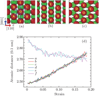
In this part, we will answer the first question. Figure 4 shows the strain rate-induced bcc to hcp phase transformation process of the Fe nanowire. Several important interatomic distances are marked and their changes with strain are displayed in Fig. 4(d). At the initial state, the nanowire is a bcc structure with lattice constant of 0.285 nm (namely e = f = 0.285 nm); and distance between the first nearest neighbor atoms is 0.247 nm (namely a = b = c = d = 0.247 nm). With increasing strain, a, b, c, and d increase while e and f decrease accordingly. When the strain reaches 16.0%, the six interatomic distances (namely a, b, c, d, e, and f) are equal to 0.271 nm; at this moment, the structure of bcc (110) planes changes into a close-packed hexagon structure (Fig. 4(b)); and then the relative slides between the atomic layers transform the crystal into hcp structure (Fig. 4(c)). During sliding, some stacking faults may be produced, which is the reason why a few layers of fcc atoms can be found in the Fig. 2(e). Consequently, the ABAB-stacked (110) planes of the bcc crystal transform into (0001)hcp close-packed planes; the [110]bcc direction transforms into the [1010]hcp direction, and the [001]bcc direction transforms into [1210]hcp direction.

Fig. 4. The mechanism of strain-rate-induced phase transformation from bcc to hcp Fe; and the change of the distances between the specified atoms during the strain-rate-induced phase transformation. The red and green balls represent Fe atoms which locate at two different (110) layers.

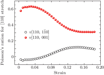
We noticed that this bcc-to-hcp martensitic phase transition mechanism is identical to the martensitic phase transition mechanism during shock compression of Fe along [001] direction;[6] this is to say that compressing the Fe along [001] direction has the same effect as stretching it along [110] direction. This interesting and important phenomenon can be understood by considering the unique Poisson’s ratio of iron for [110] stretch. Figure 5 gives the Poisson’s ratio of Fe as a function of strain for [110] stretch. v[110, 110] and v[110, 001] are the Poisson’s ratios for a [110] stretch, measured for [110] and [001] lateral directions, respectively. From Fig. 5, it can be found that when the strain is not more than 6%, the Fe has negative Poisson’s ratio for [110] lateral direction but a larger positive Poisson’s ratio for [001] lateral direction. (This quality of iron has been comprehensively studied by Ray H. Baughman[34].) This is to say that the [110] direction expands but the [001] direction contracts for [110] stretch. With continuing [110] stretch, v[110, 110] increases and v[110, 001] decreases; however, the v[110, 001] is still far greater than v[110, 001]. As a result, just before the martensitic phase transition happens, the unit cell length along [110] direction almost keeps constant (from 0.404 nm to 0.396 nm), and the Fe mainly contracts along [001] direction; this has a similar effect as compressing iron along [001] direction.

Fig. 5. The Poisson’s ratio of Fe as a function of strain for [110] stretch. v[110, 110] and v[110, 001] are the Poisson’s ratios for a [110] stretch, measured for [110] and [001] lateral directions, respectively.
4.2. Temperature and strain rate effect on the martensitic phase transition

In the following part, we will answer the question why the bcc-to-hcp martensitic phase transition is related to high strain rate or low temperature. The energy barrier of the bcc-to-hcp martensitic phase transition process is calculated using a so-called induced energy minimization method (IEM)[35,36] and displayed in Fig. 6, which indicates that the transition process can be divided into two successive stages. In the first stage (from point A to point B in Fig. 6), the structure of bcc (110) planes changes into close-packed hexagonal structure; the energy barrier of this stage can be calculated as 0.167 eV/atom. In the second stage (from point B to point D in Fig. 6), the relative slides between the close-packed hexagon atomic layers transform the crystal into hcp structure; the energy barrier of this stage is calculated as 0.009 eV/atom. So the energy barrier of the phase transition process can be calculated as E0 = 0.176 eV/atom; this is to say that during the Fe nanowires’ stretch process along [110] direction, if the elastic strain energy is larger than 0.176 eV/atom, the bcc-to-hcp martensitic phase transition will happen (at 0 K). Furthermore, if the thermal activation effect is considered, the energy barrier of the phase transition can be calculated as:[37]

where k and T are Boltzmann constant and absolute temperature, respectively.

Fig. 6. The potential energy per atom as a function of reaction coordinates during the bcc-to-hcp phase transformation.

It is well known that the dislocation nucleation from the free surface of the nanowire is a thermal activation process. Zhu[16] has developed an atomistic modeling framework to address the probabilistic nature of surface dislocation nucleation, which shows that the activation volume associated with surface dislocation nucleation is characteristically in the range of 1 − 10b3 (b is the Burgers vector). Such small activation volume leads to sensitive temperature and strain-rate dependence of the nucleation stress (the maximum stress of the stress–strain curve). Within the linear approximation of stress-dependent activation energy, the dislocation nucleation stress (or the elastic limit stress on the strain–stress curve) is given by equation:[16]

where T is the absolute temperature, k is the Boltzmann constant, N is the number of nucleation sites, υ0 is the jump frequency, E is the elastic modulus, and is the applied strain rate, Ω is the activation volume. The first term Q*/Ω is the theoretical strength of a perfect crystal. Equation (2) indicates that the dislocation nucleation stress increases with the increasing of strain rate or the decreasing of temperature, which is consistent with our work (Fig. 1 and Fig. 3). From Fig. 1 and Fig. 3 we find that before plastic deformation occurs, the stress has a linear relationship with strain; so the elastic strain energy of the nanowire can be calculated as:[38]

where V is volume of the nanowire, G and σ denote the Young’s modulus and stress of the nanowire, respectively. Based on the above analysis, we can find that the maximum value of the elastic strain energy (Emax) during the stretch process also increases with the increase of strain rate or the decreasing of temperature.

The Fe nanowires have two plastic deformation mechanisms for a [110] stretch, namely, the dislocation nucleation mechanism and the bcc-to-hcp martensitic phase transformation mechanism. If the elastic strain energy reaches the energy barrier for the martensitic phase transition, the bcc-to-hcp martensitic phase transformation mechanism will control the plastic deformation of the nanowires; otherwise, the dislocation nucleation mechanism will work.

Figure 7 displays the maximum value of the elastic strain energy (Emax) as a function of temperature under different strain rates. From the figure it can be seen that for the strain rates larger than 5 × 10¹⁰ s−1, the Emax is higher than the energy barrier of the martensitic phase transition; this means that the plastic deformation of the Fe nanowires is controlled by the bcc-to-hcp martensitic phase transformation mechanism. For strain rates lower than 5 × 10¹⁰ s−1, the plastic deformation mechanism of the Fe nanowires is related to temperature: namely, at lower temperatures the Emax is higher than the energy barrier for the martensitic phase transition and the plastic deformation of the Fe nanowires will be controlled by the bcc-to-hcp martensitic phase transformation mechanism. On the contrary, at higher temperature, the Emax is lower than the energy barrier of the martensitic phase transition, the plastic deformation of the Fe nanowires is controlled by the dislocation nucleation mechanism.
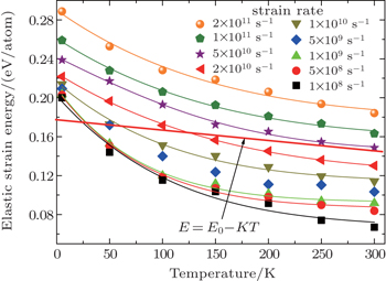
Fig. 7. The maximum value of the elastic strain energy as a function of temperature under different strain rates.

Furthermore, from Fig. 7 we can calculate out the transition temperatures at different strain rates (transition temperature is defined as the temperature at which the two plastic deformation mechanisms can transform to each other at constant strain rate). By using these transition temperatures at different strain rates, we can further fit a boundary line between the two plastic deformation mechanisms in temperature–strain rate space and displays it in Fig. 8. In Fig. 8, the dislocation nucleation mechanism and the bcc-to-hcp martensitic phase transformation mechanism are located at green and blue regions, respectively; moreover, we also display the simulation results at various strain rates and temperatures. The red pentagons represent dislocation nucleation mechanism, and the black triangles represent the bcc-to-hcp martensitic phase transformation mechanism. It can be found that our theoretical result is consistent with the simulation results very well.

Fig. 8. The proposed plastic deformation map in the temperature–strain rate space for Fe nanowires.
5. Summary

In summary, the plastic deformation mechanism of Fe nanowires is studied using molecular dynamics simulation method by applying uniaxial tension along the [110] direction at constant strain rate and temperature. The simulation results show that at high strain rate or low temperature, the bcc-to-hcp martensitic phase transformation mechanism controls the plastic deformation of the nanowires; however, at low strain rate and high temperature the plastic deformation mechanism will transform into a dislocation nucleation mechanism. It is found that this bcc-to-hcp martensitic phase transition mechanism is identical to the bcc-to-hcp martensitic phase transition mechanism during shock compressing Fe along [001] direction, and the underlying reason can be attributed to the unique Poisson’s ratio of iron for [110] stretch. Furthermore, the underlying cause of why the bcc-to-hcp martensitic phase transition mechanism is related to high strain rate and low temperature is also carefully studied, and based on the study a strain rate–temperature plastic deformation map for iron nanowires has been proposed; this map shows a vivid story about the transition between the two different plastic deformation mechanisms, and will help us develop in-depth understanding of the plastic deformation of Fe nanowires.

Reference
1Tateno SHirose KOhishi YTatsumi Y 2010 Science 330 359
2Stixrude L 2012 Phys. Rev. Lett. 108 055505
3Ping YCoppari FHicks D GYaakob B 2013 Phys. Rev. Lett. 111 065501
4Anzellini SDewaele AMezouar MLoubeyre P 2013 Science 340 464
5Bancroft DPeterson E LMinshall S 1956 J. Appl. Phys. 27 291
6Kadau KGermann T CLomdahl P SHolian B L 2002 Science 296 1681
7Kadau KGermann T CLomdahl P SAlbers R CWark J SHigginbotham AHolian B L 2007 Phys. Rev. Lett. 98 135701
8Pang W WZhang PZhang G CXu A GZhao X G 2014 Sci. Rep. 4 3628
9Pang W WZhang PZhang G CXu A GZhao X G 2014 Sci. Rep. 4 5273
10Wang S JSui M LChen Y TLu Q HMa EPei X YLi Q ZHu H B 2013 Sci. Rep. 3 1086
11Quan JYang X Y2015Acta Phys. Sin.64116201(in Chinese)
12Xie S FChen S DSoh A K 2011 Chin. Phys. Lett. 28 066201
13Liao HRuan S CLi Let al. 2011 Chin. Phys. Lett. 28 106104
14Diao JGall KDunn M L 2004 Nano Lett. 4 1863
15Rabkin ENam H SSrolovitz D J 2007 Acta Mater. 55 2085
16Zhu TLi JSamanta ALeach AGall K 2008 Phys. Rev. Lett. 100 025502
17Ikeda HQi YÇagin TSamwer KJohnson W LGoddard W A 1999 Phys. Rev. Lett. 82 2900
18Branício P SRino J P 2000 Phys. Rev. 62 16950
19Chen M WMcCauley J WHemker K J 2003 Science 299 1563
20Xiong YKang KBae GYoon SLee C 2008 Appl. Phys. Lett. 92 194101
21Luo X TYang G JLi C JKondoh K2011Scr. Mater.65581
22Xie H XYin F XYu TLu G HZhang Y G 2015 Acta Mater. 85 191
23Plimpton S1995J. Comput. Phys.1171
24Plimpton S2007Large-scale atomic/molecular massively parallel simulatorSandia National Laboratories
25Zhou M 2003 Proc. R. Soc. Lond. 459 2347
26Tschopp M AMcDowell D L 2007 Appl. Phys. Lett. 90 121916
27Tschopp M ASpearot D EMcDowell D L 2007 Model. Simul. Mater. Sci. Eng. 15 693
28Tschopp M AMcDowell D L 2008 J. Mech. Phys. Solids 56 1806
29Spearot D ETschopp M AMcDowell D L 2009 Scr. Mater. 60 675
30Mendelev M IHan SSrolovitz D JAckland G JSun D YAsta M 2003 Philos. Mag. 83 3977
31Malerba L 2010 J. Nucl. Mater. 406 19
32Cleveland C LLuedtke W DLandman U 1999 Phys. Rev. 60 5065
33Stukowski A 2010 Modell. Simul. Mater. Sci. Eng. 18 015012
34Baughman R H 1998 Nature 392 362
35Xie H XYu TTang C C2013Modell. Simul. Mater. Sci. Eng.21055008
36Xie H XYin F XYu T 2014 Appl. Phys. Lett. 104 031911
37Hirth J PLothe J1982Theory of DislocationsNew YorkWiley
38Rösler JHarders HBäker M2006Mechanical Behaviourof Engineering MaterialsGerman ednTeubner VerlagWiesbaden