† Corresponding author. E-mail:
Laser-induced damage in fused silica optics greatly restricts the performances of laser facilities. Gray haze damage, which is always initiated on ceria polished optics, is one of the most important damage morphologies in fused silica optics. In this paper, the laser-induced gray haze damages of four fused silica samples polished with CeO2, Al2O3, ZrO2, and colloidal silica slurries are investigated. Four samples all present gray haze damages with much different damage densities. Then, the polishing-induced contaminant and subsurface damages in four samples are analyzed. The results reveal that the gray haze damages could be initiated on the samples without Ce contaminant and are inclined to show a tight correlation with the shallow subsurface damages.
The maximum output power of a high power laser facility is ultimately limited by the laser induced damage resistance of the optical components making up the system.[1] Pure fused silica as one of the most important optical materials has a wide bandgap and very high intrinsic laser-induced damage threshold.[2] However, even the highest quality optical components have lots of manufacturing-induced subsurface defects which restrict the damage resistance.[3,4] Once the damage happens in fused silica optics under 355-nm laser fluence, there are two distinctly different damage morphologies: the catastrophic damage and the gray haze damage.[5] The catastrophic damages represent the large single damage craters which have a typical width of tens of microns each.[6] Recent studies suggest that near-surface defects, such as absorptive contaminant and subsurface cracks are primarily responsible for initiating the catastrophic damages.[7–9] The gray haze damages, which are always initiated on the ceria polished surfaces, refer to the high-density pin-point damages with a typical width of ∼ 1 μm.[10–12] The gray haze damages always occur at a low fluence compared with the catastrophic damages.[11] Moreover, the high-density gray haze damages can scatter light mightily and deteriorate the laser beam quality. It was indicated in Refs. [13]–[15] that eliminating the ceria polishing-induced redeposition layer, through either chemical etching or substitution of ZrO2 polishing for ceria polishing, could reduce or remove the gray haze damages. However, in the present study, we find that the fused silica samples polished with different materials (CeO2, Al2O3, ZrO2, and colloidal silica) all present gray haze damages under a laser fluence. Combining hydrofluoric acid (HF) etching and differential interference contrast (DIC) microscopy reveals that the gray haze damages tend to show a tight correlation with the shallow subsurface damages.
Four commercially available precisely polished UV-grade fused silica samples (labeled A, B, C, and D), each of which was 50 mm in diameter and 5 mm in thickness, were manufactured by different procedures. Firstly, four samples were etched in HF-based acid with a constant material removal of 20 μm per side to substantially eliminate (or expose) the previous subsurface damages.[16] Then, samples A, B, C, and D were precisely polished with commercially available CeO2, Al2O3, ZrO2, and colloidal silica slurries to remove a 10-μm-thick layer from each of their exit surfaces, respectively. All the polishing processes were performed under the same conditions such as pressure and rotation speed using a polishing cloth. The material removal rates of polishing with ceria (∼ 2 μm/h), Al2O3 (∼ 2 μm/h), ZrO2 (∼ 1 μm/h), and colloidal silica (∼ 0.5 μm/h) slurries were different as a result of the different particle size distributions and chemical activities. Thus, four samples were polished for different times to achieve the same removal depth (10 μm in this text). To avoid cross contaminations of different slurries in the polishing process, a fresh polishing cloth was used to polish each sample. All samples were cleaned using the same multifrequency ultrasonic cleaning procedure prior to any tests. The size distributions of the polishing slurries were measured by a Zetasizer Nano ZS nano-particle analyzer. The average particle sizes of colloidal silica, ZrO2, Al2O3, and CeO2 were 60, 350, 860, and 980 nm, respectively. The surface roughness values of all samples were measured with a white light interferometer. Samples A, B, C, and D presented the average surface roughness values of 1.2, 1.5, 0.9, and 0.7 nm RMS, respectively. Note that the colloidal silica slurry had the smallest average particle size while the ceria and Al2O3 slurry has the largest average particle size. It inclines to indicate that the larger polishing particle size causes the worst surface roughness, which is consistent with a previous result in Ref. [17]. The depth profiles of the contaminant elements in the redeposition layers were detected by a Model 2100 Trift II time-of-flight secondary ion mass spectrometry (TOF-SIMS).
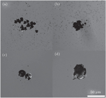
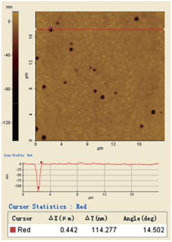
A tripled Nd:YAG laser was used at a wavelength of 355 nm in the laser induced damage test equipment. The pulse is a single longitudinal mode with 5 ns (FWHM). During the test, the beam was focused on the exit surface to provide a near Gaussian beam with a diameter of about 0.7 mm at 1/e2 of maximum intensity. The damage threshold test was performed using the standard “1-on-1” test mode. The morphologies of the laser damages were recorded using a Leica DM4000M optical microscope. Raster scan damage test was used to estimate the gray haze damage density at a certain fluence and the scan area is about 10 mm2 when considering the high density of the gray haze damages. Then the atomic force microscope (AFM) images of the gray haze damages were obtained to reveal the depth profile information.
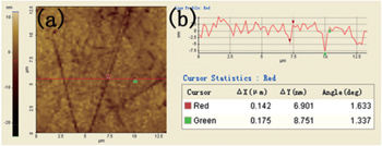
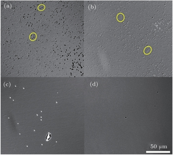
After the previous measurements, all samples were etched 1um-thick layer from both sides in HF based acid to expose and widen the invisible subsurface damages. Since the DIC images are much more sensitive to small dots and shallow scratches than normal bright field images.[18] Combining HF etching and DIC images were used to analyze the subsurface damages in polished surfaces. To obtain the subsurface damage density, ten DIC images (650 μm × 480 μm) of each sample are recorded at evenly spaced after the HF etching process by a Leica DM4000M optical microscope. The specific subsurface damage density was estimated as the ratio of the total number of the damages to the total area. The AFM images were captured to analyze the depths and widths of the subsurface damages. DIC images of the gray haze damages were also obtained after the HF etching process.
The classic initial laser induced damage morphologies of the four samples are illustrated in Fig.
| Table 1. Laser induced gray haze damage densities of four samples at a fluence of 15 J/cm2. . |
The SIMS tests reveal that the main contaminant elements consist of Ce, Fe, Al, Zr, Cu, K, and Na. All of the contaminant elements show rapid decrease and disappear at the depth of 100 nm as usual, but the content values of the contaminant elements are much different from each other. The depth profile data are normalized with the silicon ion number (counts 104) as a standard for comparison. The cumulated relative amount of each element in the 100 nm redeposition layers is presented in Table
| Table 2. Cumulated quantities of each element in the redeposition layers of four samples. . |
To obtain the statistical distribution of the subsurface damages in full size, ten DIC images are recorded in each sample after the HF etching process. Many exposed subsurface damages such as continuous polishing scratches and polishing dots are clearly observed. Considering the fact that from each of these four fused silica samples has been removed a 20-μm-thick layer through HF etching prior to the final polishing process, most of the subsurface damages observed here should be produced in the final polishing process. For clarity of presentation, figure
| Table 3. Polishing induced shallow subsurface damage densities of four samples. . |
The much different distributions of the shallow subsurface damages in four samples indicate that the formation of the subsurface damages tightly depends on the polishing parameters (particle size distribution). In the chemical mechanical polishing process, the main process composed of the formation of a soft hydrated layer and then the removal of the hydrated layer by abrasive particles.[19,20] So during the polishing, the loaded polishing particles would indent into the surface or plough up the surface to remove the materials, which will form shallow polishing dots or continuous polishing scratches (as indicated in Fig.
A comparison of Table
In this work, the laser induced gray haze damages with much different densities are found in fused silica optics polished with colloidal silica, ZrO2, CeO2, and Al2O3 slurries. The SIMS test proves that the gray haze damages could be initiated on the samples without Ce contaminant in the redeposition layer. Combining HF etching and DIC images is used to analyze the polishing-induced subsurface damages. It reveals that the densities of the polishing dots and the gray haze damages have the same orders of magnitude. The density of the gray haze damages increases with the densities of the polishing dots and scratches increasing. In addition, some gray haze damages are directly initiated on the continuous polishing scratches. Thus, the polishing-induced shallow subsurface damages are inclined to show a tight correlation with the initiation of the gray haze damages. These results can provide momentous support for further understanding the damage mechanism of gray haze damages.
| 1 | |
| 2 | |
| 3 | |
| 4 | |
| 5 | |
| 6 | |
| 7 | |
| 8 | |
| 9 | |
| 10 | |
| 11 | |
| 12 | |
| 13 | |
| 14 | |
| 15 | |
| 16 | |
| 17 | |
| 18 | |
| 19 | |
| 20 | |
| 21 | |
| 22 | |
| 23 | |
| 24 | |
| 25 | |
| 26 | |
| 27 |


