Broadband tunability of surface plasmon resonance in graphene-coating silica nanoparticles
[Shi Zhe1, †,  , Yang Yang1, 2, †, , Gan Lin1, Li Zhi-Yuan‡, ]
, Yang Yang1, 2, †, , Gan Lin1, Li Zhi-Yuan‡, ]
|
|


† These authors contribute equally to this work.
‡ Corresponding author. E-mail:
Project supported by the National Natural Science Foundation of China (Grant Nos. 11204365 and 11434017) and the National Basic Research Program of China (Grant No. 2013CB632704).
Graphene decorated nanomaterials and nanostructures can potentially be used in military and medical science applications. In this article, we study the optical properties of a graphene wrapping silica core–shell spherical nanoparticle under illumination of external light by using the Mie theory. We find that the nanoparticle can exhibit surface plasmon resonance (SPR) that can be broadly tuned from mid infrared to near infrared via simply changing the geometric parameters. A simplified equivalent dielectric permittivity model is developed to better understand the physics of SPR, and the calculation results agree well qualitatively with the rigorous Mie theory. Both calculations suggest that a small radius of graphene wrapping nanoparticle with high Fermi level could move the SPR wavelength of graphene into the near infrared regime.
Graphene is a two-dimensional (2D) material composed of one layer of carbon atoms arrayed in a honeycomb lattice. It has an unusual linear dispersion band structure and ultra-high electron mobility at room temperature.[1,2] Due to its low carrier quantity, the Fermi level of graphene can be easily adjusted by electrostatic gate or chemical doping method.[1,3] With these significant novel properties, graphene shows great potential in making next generation high frequency field effect transistors (FET) to 100 GHz[4,5] to overpass the limit of silicon transistors.
Beyond the interests in electronics, much research interests in photonic and optoelectronic properties of graphene[6] have been aroused recently. Graphene can be integrated with nanophotonic structures, such as waveguide,[7] cavity,[8] fiber,[9] and even solar cell[10] to make the devices have more functionalities, such as faster modulation efficiency and higher energy exchange efficiency. Usually the interaction between graphene and light is fairly weak, e.g., it is well known that only 2.3% of the incident light in visible and near-infrared spectrum range is absorbed by graphene.[11] In order to enhance the interaction, three methods are usually adopted. The first one is to introduce an electromagnetic field confinement mechanism by placing plasmonic structures[12–14] on graphene or adhering graphene on resonant cavities.[15–17] The second one is to make the graphene interact with electromagnetic field for a longer distance, e.g., by integrating graphene with waveguides[7] and fibers.[9] The third one is to excite the intrinsic plasmon resonance in graphene, e.g., by fabricating graphene ribbons[18] or placing graphene on gratings.[19] However, all of those schemes are based on a planar device structure, where graphene is placed on a 2D optical structure and usually a plasmonic resonance wavelength at mid-infrared wavelength with limited tunability is observed, probably due to the 2D properties of graphene and optical structures.
Suppose graphene is integrated with a zero-dimensional (0D) optical nanostructure, such as covering graphene on the surface of a nanoparticle, what will happen? Some pioneering works have been done in these fields. For instance, wrapping oxidized graphene on a hollow SnO2 ball can make high-performance anode materials for lithium ion batteries,[20] and a hetero-structure of graphene covered silicon carbide (SiC) nanoparticle, directly grown by decomposing SiC, shows great potential in photocatalytic and hydrogen production.[21,22] The novel properties of these graphene decorated nanoparticles indicate that the platform of an integrated graphene-nanoparticle composite could bring new phenomena and functionalities that are absent in pure graphene.
To further explore the novel optical phenomena and properties in these graphene hybrid nanostructures, we propose a model structure of integrating graphene on the curved surface of a nanoparticle to enhance the interaction of graphene with light through the curved graphene surface. Because of the curved surface, local surface plasmon resonance (SPR) can be excited in graphene wrapped on the nanoparticle surface, and the SPR wavelength can be modulated in a broad range from mid-infrared to near infrared wavelength, which is useful for military and medical science applications.
As a principle model, we study a graphene coating silica spherical nanoparticle and theoretically calculate the SPR wavelength as functions of graphene Fermi levels and the geometric of the silica nanoparticle. In our graphene coating nanoparticle model, graphene is anisotropic. To calculate SPR preciously, Mie theory[23] should be used, which is a little bit complicated for this composite nanoparticle. Notice that the size of nanoparticle (< 100 nm) is much smaller than the wavelength of light (several micrometers), we can use a simple approach called the equivalent dielectric permittivity theory to estimate the optical response characteristic of this composite nanoparticle. The equivalent dielectric permittivity theory is much simpler and easier to use than Mie theory to obtain the resonance spectrum. The calculation results from the two theoretical models will be compared and analyzed. It turns out that the equivalent dielectric permittivity theory could conveniently predict the resonance spectrum of the hybrid graphene–nanoparticle structure with a sufficiently good precision, but without a complex calculation as used in Mie theory. Besides, the 0D hybrid structure of graphene and silica nanoparticle could act as a new platform for enhancing the optical response for near infrared light.
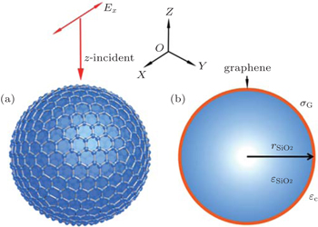
In this work, a small spherical core–shell nanoparticle with a core component of silica and a shell of a monolayer of graphene covering the outer surface of the silica nanoparticle is studied. A plane wave light propagating along the z-axis direction with the linear polarized electric field in the x-axis direction is used to excite the SPR of the nanoparticle. The geometry of the core–shell nanostructure is schematically shown in Fig.


 | Fig. 1. Schematic of a 0D core–shell structure with graphene wrapping on silica nanoparticle. (a) The light blue ball presents the silica core with a radius of rSiO2, and its surface is covered with a monolayer of graphene in thickness of tG. A plane wave propagating along the z-axis with the electric field polarized along the x axis is used to excite SPR in graphene wrapping silica nanoparticle. (b) The cross-section schematic of the core–shell structure of the graphene wrapping nanoparticle. |
Here, e is the elemental electron charge, kB is the Boltzmann constant, ħ is the Planck constant, T is the temperature (here, a room temperature of 300 K is used), Ef is the Fermi level of graphene, and τG is the carrier relaxation time in graphene. The graphene permittivity ε∥ can be changed by variation of the Fermi level of graphene. Here, we set the graphene mobility as 10000 cm2/V·s, which is commonly used in other calculations.[12] Thus, we can deduce the value of ε∥ at different Fermi levels of graphene from the above relation.
When the SPR of the core–shell nanoparticle is excited, its extinction spectrum and resonance peak position can be calculated based on our theoretical models. In our calculations, the two theoretical models mentioned above are adopted to find the SPR peak of the graphene-covering silica nanoparticles. One is calculated by the equivalent dielectric permittivity method applied to the core–shell nanoparticle and the other is calculated by precise Mie theory. These two models give similar results and their pros and cons are also analyzed and discussed.
Mie theory is a precise calculation method widely used in describing the scattering of an electromagnetic plane wave by a homogeneous sphere or stratified spheres.[23] It can handle any size of the scattering particles, whether comparable to, much smaller than or much larger than the wavelength of the light. Using the Mie theory, we can precisely calculate the extinction spectrum of the graphene wrapped core–shell nanoparticle[26,27] under illumination of an incident plane wave, as illustrated in Fig.
In this model, the surface current


The time-harmonic electromagnetic field


The normalized extinction cross section can be expressed as


Due to the low carrier density in graphene, the SPR peak of intrinsic graphene nanostructures are located in mid-infrared wavelength (∼ 7–8 μm). As the size of the nanoparticle considered in our structural model is very small compared to the resonance wavelength, i.e., a 50-nm nanoparticle radius is only one percent of the resonance wavelength. Thus, we can treat the core–shell graphene wrapped nanoparticle as an isotropic homogenous particle with an equivalent homogenous dielectric permittivity without considering graphene as an anisotropic dielectric material and distinguishing the material difference between the core and shell.
In using the equivalent dielectric permittivity approximation, we can treat the anisotropic dielectric permittivity of graphene as an equivalent isotropic dielectric permittivity material by setting its equivalent dielectric permittivity as


Then the scattering, absorption, and extinction cross sections, which are Csca, Cabs, and Cext, respectively, of the core–shell graphene wrapping nanoparticle, with an equivalent dielectric permittivity of εnp, can be calculated via the following relation:[26]


According to the two models described above, the SPR extinction spectra of the core–shell graphene wrapping core–shell nanoparticle can be calculated with different radii of the nanoparticles and different Fermi levels of graphene covering on the surface. The extinction spectra of the nanoparticle calculated based on the equivalent dielectric permittivity method and Mie theory are shown in Fig.
As is well known, there are many methods to modulate the Fermi level of graphene on a nanoparticle, such as putting the nanoparticle in an electrical field induced by applying an electrostatic gating. On the other hand, a uniform modulation of the Fermi level of graphene can be obtained through chemically doping graphene with boron or nitrogen element.[29]
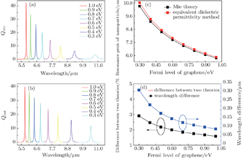
As graphene is coating on a silica nanoparticle surface, the core–shell structure is constructed. The calculated extinction spectra at different Fermi levels of graphene varying from 1.0 eV to 0.3 eV in a step of 0.1 eV are shown in Fig.
The difference of the resonant wavelengths at the same Fermi level calculated by the two models are shown in Fig.
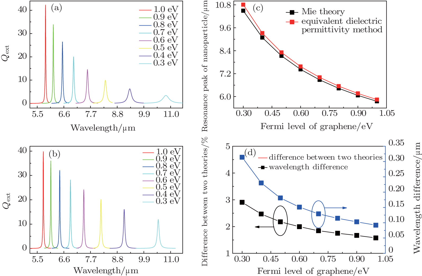 | Fig. 2. Extinction spectra of graphene wrapping core–shell nanoparticle with different Fermi levels of graphene. Extinction spectra calculated by (a) the equivalent dielectric permittivity method and (b) the Mie theory with the Fermi level of graphene wrapping silica nanoparticle change from 1.0 eV to 0.3 eV, while keeping the radius of the graphene wrapping nanoparticle fixed at 60 nm. (c) The changes of resonance peak with Fermi levels of graphene calculated by the two theories. (d) Relative resonant peak difference between the two theories for different Fermi levels of graphene. |
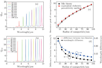
Besides the Fermi level induced change on the extinction spectrum, the effect of the nanoparticle radius on the extinction spectrum is studied further. In our calculations, we change the core–shell graphene wrapping nanoparticle radius from 10 to 100 nm in a step of 10 nm while keeping the Fermi level of graphene fixed at 0.6 eV. The extinction spectrum with different radii of nanoparticle calculated by the equivalent dielectric permittivity model and Mie theory are shown in Figs.
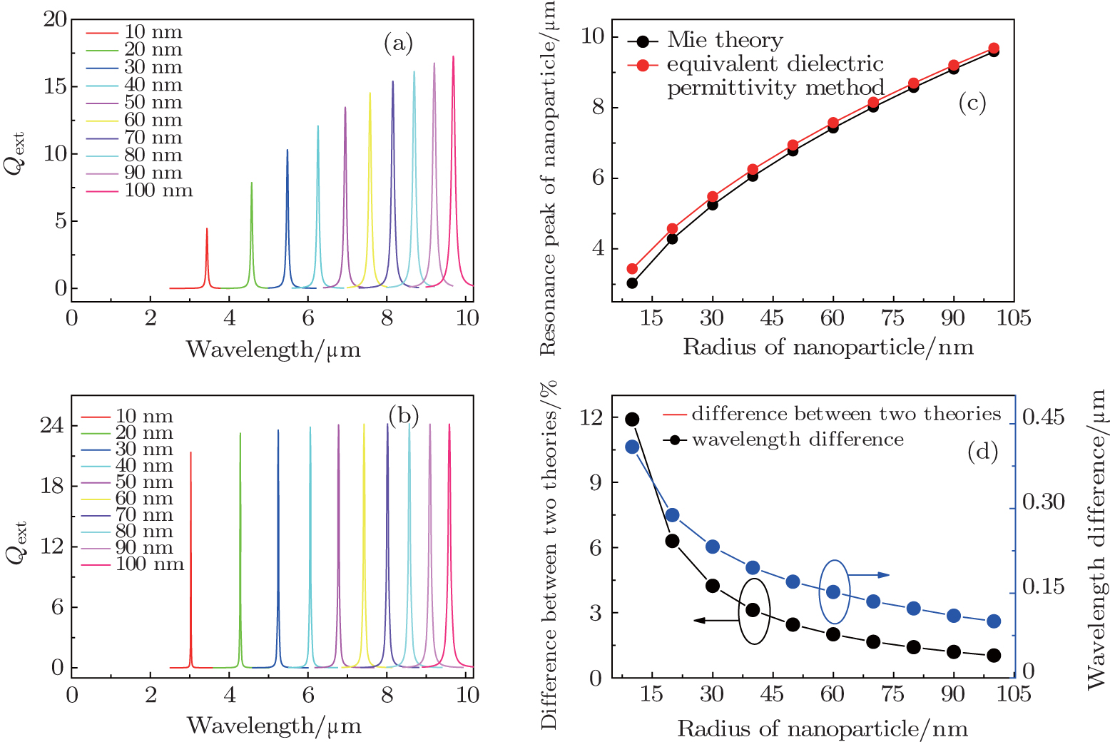 | Fig. 3. Extinction spectra of graphene wrapping core–shell nanoparticle with different radii. Extinction spectra calculated by (a) the equivalent dielectric permittivity method and (b) the Mie theory with the radius of graphene wrapping silica nanoparticle changing from 10 to 100 nm, while keeping the graphene Fermi level fixed at 0.6 eV. (c) The change of resonance peak with different radii of nanoparticle calculated by the two theories. (d) The relative resonant peak difference between the two theories at different radii of nanoparticle. |
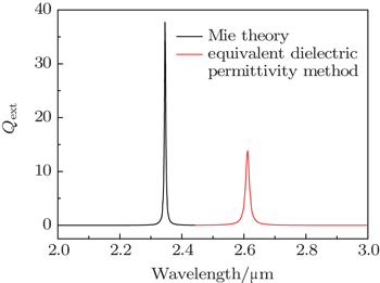
A more important thing to notice from the above systematic calculations is that one can use simple geometric configuration factor of nanoparticle to tune the SPR wavelength of graphene material in a very broad wavelength range. Remarkably one can combine an appropriate value of both the nanoparticle size (from the structural aspect) and graphene doping level (from the material aspect) to realize SPR of graphene in the near infrared wavelength. For instance, a graphene wrapping nanoparticle as small as 10 nm together with a high doping level (with the corresponding Fermi level of 1.0 eV) could possibly push the SPR wavelength to near infrared (∼ 2 μm), according to the calculation as shown in Fig.
 | Fig. 4. Extinction spectrum of graphene wrapping core–shell nanoparticle with a dope level of 1.0 eV Fermi energy and radius of 10 nm. The resonance peak of graphene coating core–shell nanoparticle can move to near infrared wavelength. |
In summary, we have proposed a graphene wrapping dielectric nanoparticle to engineer the plasmon resonance of graphene material via geometric resonance effect. The extinction spectra of the core–shell hybrid nanoparticle are calculated by using the rigorous Mie theory and a simple equivalent dielectric permittivity approximate model. The similarity and difference of the results calculated from the two theories are analyzed and discussed. It is found that the approximate model can yield the SPR wavelength of hybrid nanoparticles with a reasonably good precision compared with the rigorous Mie theory. Together with its simplicity, this effective medium approach could be very useful for estimating the optical properties of graphene hybrid nanoparticles and for engineering the SPR wavelength of graphene material.
Our calculation results show that the hybrid nanoparticle enables fine and sensitive tuning of the SPR wavelength of graphene material in a broad range from far infrared, to mid infrared, and even to near infrared regime simply by adjusting the radius of the nanoparticle and the doping level of graphene. When the structural and material aspect of the hybrid nanoparticle are closely explored and incorporated, a graphene wrapping nanoparticle with a small radius (around 10 nm) together with a high Fermi level (around 1.0 eV) will trigger a plasmonic resonance into near infrared. The broad spectral range tunability of plasmon resonance of graphene through this simple hybrid nanoparticle scheme could be potentially useful for military and medical science applications.
| 1 | |
| 2 | |
| 3 | |
| 4 | |
| 5 | |
| 6 | |
| 7 | |
| 8 | |
| 9 | |
| 10 | |
| 11 | |
| 12 | |
| 13 | |
| 14 | |
| 15 | |
| 16 | |
| 17 | |
| 18 | |
| 19 | |
| 20 | |
| 21 | |
| 22 | |
| 23 | |
| 24 | |
| 25 | |
| 26 | |
| 27 | |
| 28 | |
| 29 | |
| 30 | |
| 31 | |
| 32 |