
Numerical analysis of the optimized performance of the electron cyclotron wave system in a HL-2M tokamak
[Li Jing-Chun1, Gong Xue-Yu1, †,  , Dong Jia-Qi2, Wang Jun2, Yin Lan3]
, Dong Jia-Qi2, Wang Jun2, Yin Lan3]
|
|


† Corresponding author. E-mail:
Project supported by the National Natural Science Foundation of China (Grant Nos. 11375085, 11405082, 11505092, 11475083, and 11375053), the National Magnetic Confinement Fusion Science Program of China (Grant Nos. 2013GB104004, 2013GB111000, 2014GB107000, and 2014GB108002), and the Natural Science Foundation of Hunan Province, China (Grant No. 2015JJ4044).
The capabilities of current drive, neoclassical tearing mode (NTM) stabilization, and sawtooth control are analyzed for the electron–cyclotron wave (ECW) system in a HL-2M tokamak. Better performance of the upper launcher is demonstrated in comparison with that of a dropped upper launcher, in terms of JEC/Jbs for NTM stabilization and IECCD/(Δρtor)2 for sawtooth control. 1-MW ECW power is enough for the 3/2 NTM stabilization, and 1.8-MW ECW power is required to suppress 2/1 NTM in a single null divertor equilibrium with 1.2-MA toroidal current with the upper launcher. Optimization simulation of electron–cyclotron current drive (ECCD) is carried out for three mirrors in an equatorial port, indicating that the middle mirror has a good performance compared with the top and bottom mirrors. The results for balanced co- and counter-ECCD in an equatorial port are also presented.
Electron–cyclotron current drive (ECCD) has become a widely used way to drive current and stabilize magnetohydrodynamic (MHD) instabilities in toroidal magnetic confinement devices, since the electron–cyclotron (EC)-driven current profiles are spatially localized and the EC current drive efficiency is competitive with other approaches, such as neutral beam.[1–4] The HL-2M project is the up-grade of the HL-2A tokamak with plasma elongation up to 1.8. The goal of the HL-2M is to illuminate important research issues such as the physics of plasma confinement, transport, high energy particles, MHD stability, and the interaction between the first wall and plasma for fusion study.[5] On one hand, the HL-2M tokamak will largely take advantage of many systems of the present HL-2A, while, on the other hand, the HL-2M will have many advantages in systems of heating, current drive, diagnostics, power suppliers, etc.,[6,7] in comparison with the HL-2A.
The 1-MW electron–cyclotron wave on the HL-2M will be injected to the plasma through the single beam antenna in a Φ200-mm upper launcher (UL) port. A new 1×2 multiple beam antenna with 2-MW input power in a Φ300-mm dropped upper launcher (DUL) port, which is lowered by approximately 10 cm from the UL, is also planned. In addition, the antenna is 3×3 multiple beam and the total input power is 6 MW, composed of 6 gyrotrons of 0.5 MW each and 3 gyrotrons of 1 MW each in the equatorial port. The frequency for the electron–cyclotron wave (ECW) system to be built is 140 GHz. At 140 GHz, EC waves are injected as an X-mode and are absorbed mainly at the second harmonic, causing the density limit to be twice that of the fundamental O-mode. The functions of the two launchers are different. The equatorial launcher (EL) is good for core heating and current profile control since it induces high driven current of broad density profiles JEC, while the upper launcher is good for MHD instability control since it drives well localized current.[8] However, in order to achieve all the goals mentioned above, detailed calculations should be carried out so as to analyze the system capacity and propose an optimized construction plan before the installation of the ECW system on the HL-2M.
The function of MHD instability control is assigned to the UL. MHD instabilities, prominently the neoclassical tearing mode (NTM) and sawtooth (ST), are of significance for plasma confinement. Considering that the essence of NTM control by ECCD is a supplement of the bootstrap current loss, ηNTM = JEC/Jbs is used as a figure of merit for NTM stabilization.[9] Here, Jbs and JEC are the bootstrap and ECCD current densities at the resonant magnetic surface, respectively. For simplicity, we use the following criterion, according to the work by Perkins and Harvey,[9] to estimate the performance with ηNTM: the complete NTM suppression is not likely when ηNTM < 1.0; the complete NTM suppression may be achieved when ηNTM < 1.2; the complete NTM suppression is highly likely when ηNTM > 1.2.
The latest study also indicates that the performances for both NTM stabilization and ST control with different launchers are not the same.[10–12] Thus, it is necessary to identify launchers which have better performances in HL-2M. Two launchers, namely the UL and DUL, are also considered in our simulation. ST activity is another MHD instability that is closely related to plasma performance.[13] Both experimental and theoretical results demonstrate that the localized co-CD just inside (or counter-CD just outside) the q = 1 surface may shorten ST free periods.[14] The effectiveness of ST control lies on the modification of magnetic shear inside the q = 1 surface. Here, the quantity ηs = IECCD/(Δρtor) 2 is used to evaluate the performance of ST destabilization,[15] where 
The main objectives of the equatorial launcher are to get higher driven current for achieving more localized density profiles efficiently with ECW.[16] Moreover, the recent experiments show that balanced co- and counter-ECCD may achieve ‘pure’ heating with equatorial launchers.[17] Here, with the HL-2M configuration, we will take a series of optimization calculations and hence obtain the optimized parameters and the conditions for pure heating, and the corresponding driven current profiles as well.
The rest of this paper is organized as follows. The TORAY code is introduced and the parameters of HL-2M are presented in Section 2. We report the efficiencies for NTM stabilization and ST control with the UL and the DUL, and a performance comparison between UL and DUL in Section 3. The capabilities of the EL are presented and the results of central co- and counter-ECCD are given in Section 4. Brief conclusions are given in Section 5.
The TORAY ray tracing code was developed at General Atomics and is primarily aimed at calculating the ECW trajectory, deposition, and current drive.[18–21] Its main characteristics are easy to read, efficient, and highly modulized. So far, TORAY has been commonly benchmarked with other linear, quasi-linear,[22,23] Gaussian beam codes, and quasi-optical codes. Here, thirty rays with a Gaussian distribution in the TORAY code were chosen to launch under different conditions, and the Lin-Liu model[24] was chosen to calculate the current drive efficiency. The beam width here is 2 cm. For TORAY, the poloidal injection angle α is the counter-clockwise angle measured from the up vertical direction. The toroidal injection angle β is the counter-clockwise angle measured from the direction of the major radius on the equatorial plane at the launch point.[25]
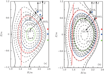
The parameters of the HL-2M tokamak are as follows:[26] major radius R = 1.78 m, minor radius a = 0.65 m, elongation κ = 1.87, triangularity δ = 0.45, plasma current IP = 1.0 & 2.0 MA, and the magnetic field at magnetic axis Bt = 1.82 T for SD1 and Bt = 2.0 T for SD2. The scenarios of the two single-null diverted HL-2M equilibria, shown in Fig.

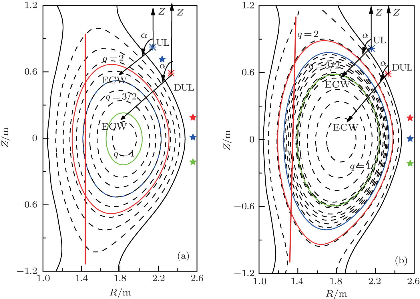 | Fig. 1. (a) HL-2M scenario SD1, with Ip = 1.2 MA, the three solid contours are the flux surfaces of q = 2, q = 3/2, and q = 1. The two asterisks indicate the locations of the upper (UL, R = 2.1 m, Z = 0.75 m) and the down upper (DUL, R = 2.3 m, Z = 0.55 m) launchers, respectively. The three pentagrams represent the locations of the top (R = 2.52 m, Z = 0.2 m), middle (R = 2.52 m, Z = 0.0), and bottom (R = 2.52 m, Z = −0.2) midplane launchers, respectively. (b) Scenario SD2, with Ip = 2.0 MA, the other parameters are the same as those for panel (a). The poloidal injection angle α and the resonance curves are marked in both panels. |
| Table 1. Parameters of the HL-2M reference scenarios. . |
In order to realize heating and current drive at the plasma edge, and real time control of MHD instability with ECW, an ECRH upper port launcher will be built on the HL-2M. In this launcher, a beam switch will be equipped in the transmission line system. As a result, if we want to control MHD instabilities with ECW, then the upper antenna can be used; if our aims are to implement the central heating and current drive, the equatorial antenna should be switched on. As mentioned before, there are two plans for the upper antenna, i.e., the UL and DUL. For the HL-2M, both launchers cover almost the whole plasma cross section. We will compare the performances of the two launchers in terms of the figures of merit for their main physics objectives in the following.
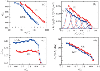
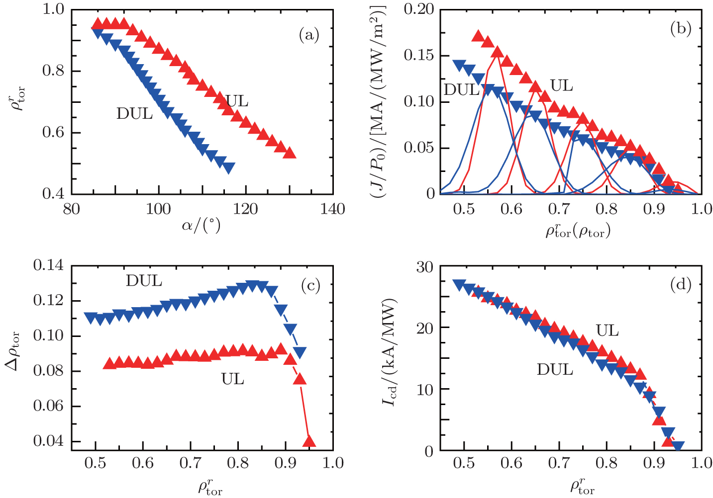
The ECCD calculations with the TORAY code are carried out for both the UL and DUL launchers. It is generally true that the figures of merit IECCD/(Δρtor)2 have their maximum values around the same toroidal launch angle for all flux surfaces under consideration in ITER,[11] which is also confirmed in our simulation in the HL-2M tokamak. Thus, we can fix the toroidal launch angle and use the poloidal angle steering only to make a comparison of the performance between UL and DUL launchers. Figures 


 | Fig. 2. Radial deposition position     |
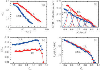
 | Fig. 3. The same as Fig. |
In order to compare and analyze the efficiencies of NTM stabilization with 1MW ECCD for UL and DUL launchers, we calculate the figures of merit for 2/1 and 3/2 NTM stabilization in the two scenarios. The parameters relevant to the best figure of merit for UL and DUL are shown in Tables
| Table 2. Parameters for the best figure of merit for UL with 1-MW ECW injected. . |
| Table 3. Parameters for the best figure of merit for DUL with 1-MW ECW injected. . |
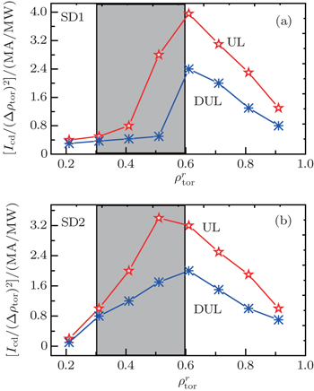
Concerning the performances of the two launchers for ST control, the most accurate calculations require transport modeling, including a model that incorporates the alpha particles stabilizing effect.[29,30] However, it is feasible to take ηs = IECCD/(Δρtor)2 as a figure of merit to compare the efficiencies of UL and DUL. Figure 
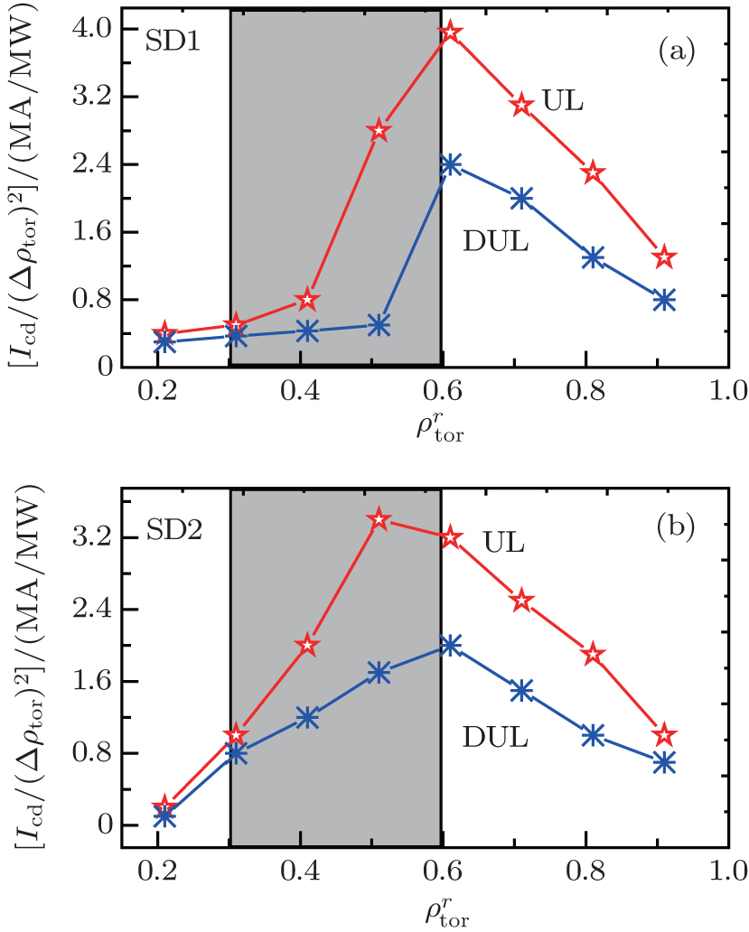 | Fig. 4. Figures of merit ηs for sawtooth control for 1-MW ECW power injected into the plasma of scenario SD1 (a) and SD2 (b) from the UL and DUL. The shaded region indicates the case where the q = 1 surface is likely to occur. |
From the above results and analyses, we may conclude that for both NTM stabilization and ST control, good performance of the upper launcher is demonstrated in comparison with that of a dropped upper launcher. This consequence comes from the fact that the CD capabilities of UL are better than those of DUL, which can be seen in Ref. [22]. The possible reasons are as follows. The first one is the toroidal effect and the other is that the optical thickness of the resonance is larger when the launch position is higher. More detailed explanations can also be found in Ref. [22].
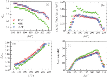
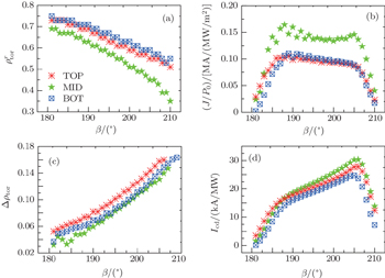
In order to identify the performances of the EL, ECWs are launched from 3 mirrors, located at R = 2.52 m and z = 0.2, 0, and −0.2 m, which are called top, middle, and bottom mirrors, respectively. The normalized radius of the peak current density location, the peak current density, the normalized e-folding width of the driven current density profile, and the total driven current versus the toroidal angle are shown in Figs.
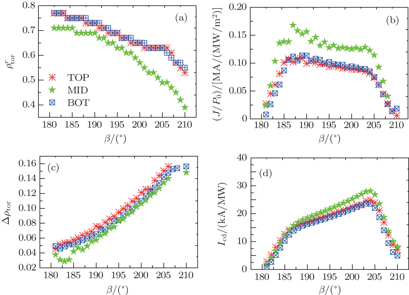 | Fig. 5. Plots of the normalized radius of the peak current density location (a), peak current density (b), the normalized e-folding width of the driven current density profile (c), and total driven current (d), versus toroidal angle for the three mirrors, i.e., the top, middle, and bottom mirrors in the equatorial port. The equilibrium and plasma parameters are those of scenario SD1. |
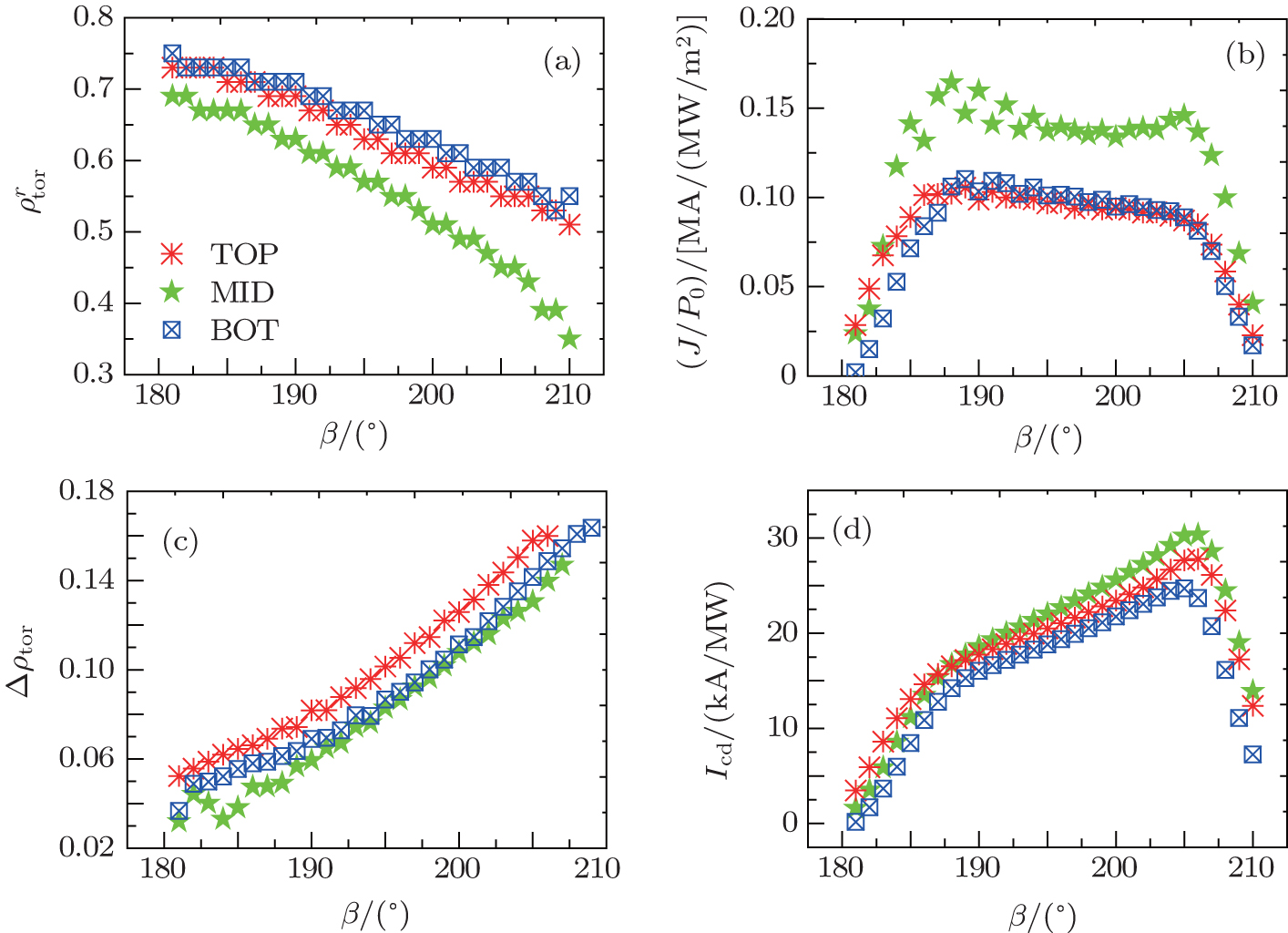 | Fig. 6. The same as Fig. |
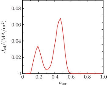
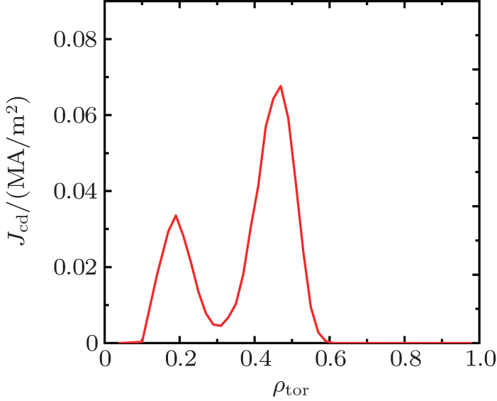 | Fig. 7. Driven current density profile for 1-MW ECW power injected from the middle mirror at β = 207° into the plasma of scenario SD1. |
As mentioned before, the main physics objective for EL is to implement the central plasma heating and current drive. Counter-ECCD (balancing co-ECCD) is required to avoid undesirable peaking of the plasma current profile at the plasma centre.[33] In some cases, it was also employed to demonstrate the possibility of full bootstrap discharge sustainment. By adding counter-ECCD beams to balance the co-ECCD component exactly, the total driven current can be annulled, leaving only the bootstrap component.[34] The current density profiles of co- and counter-ECCD calculated for the two scenarios are shown in Fig.
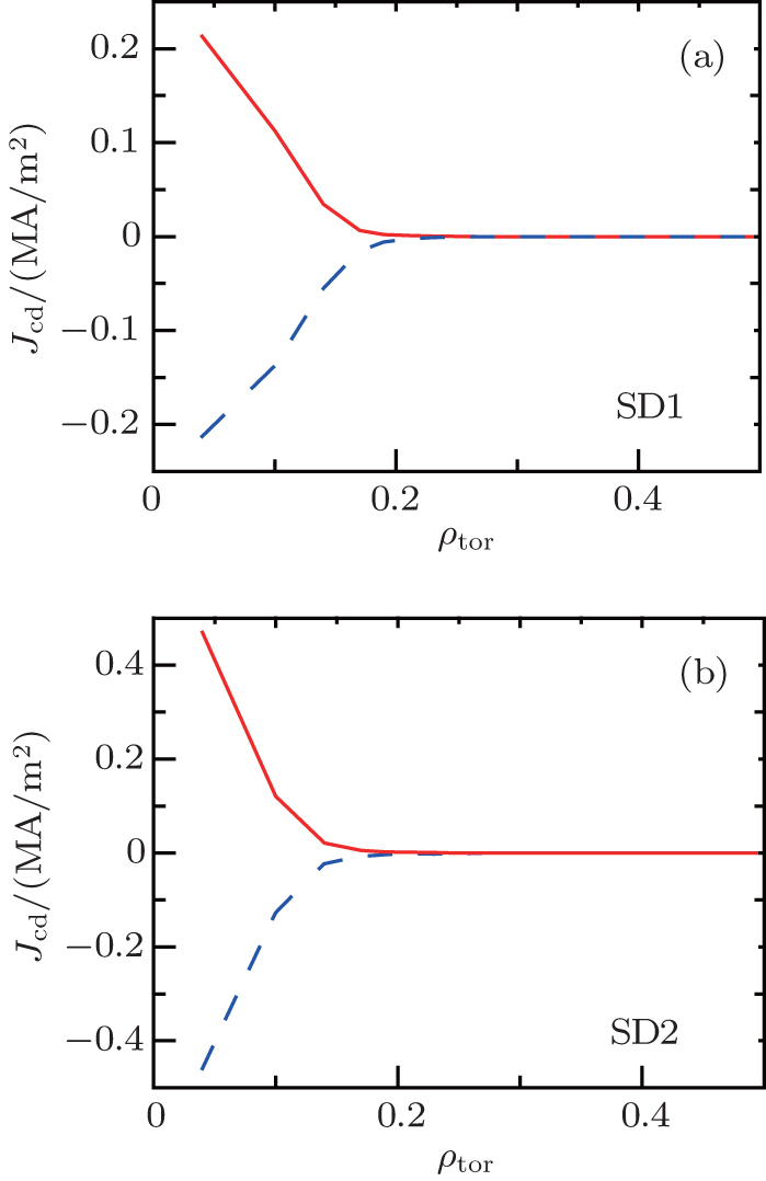 | Fig. 8. Profiles of co-ECCD and counter-ECCD for 1-MW ECW injected from the EL with a poloidal angle α = 100°, and toroidal angle β = ±214° for both scenarios. |
The capabilities of current drive, NTM stabilization and ST control for the ECW system in the HL-2M are presented using the code TORAY. The performances of the two upper launchers, namely the UL and DUL, are analyzed and compared. For both NTM stabilization and ST control, the UL, by inducing higher driven current density and narrower driven current density profiles, has better performance than the DUL. The values of the figure of merit ηNTM for NTM control are shown for 3/2 and 2/1 NTM in both SD1 and SD2, thus the required ECW power for each case of NTM stabilization is clarified. The ECCD characteristics for three mirrors in the equatorial port are also presented, and the following principle results can be drawn. First, for all the launches from the three mirrors, the values of ECCD efficiency have their maxima around the same toroidal launch angle, i.e., 204° for scenario SD1 and 206° for scenario SD2. Second, compared with the top and bottom mirror launchers, the middle mirror launcher has high current drive capabilities and a more localized current density profile. Thus, from a physics point of view, the UL and the middle mirror are highly desirable and should be chosen if the technical solution is acceptable for the HL-2M. Finally, the balanced co- and counter-ECCD in the equatorial port is achieved, demonstrating the feasibility to achieve ‘pure’ heating with the equatorial port in the HL-2M tokamak. The performance analysis and results in this paper will certainly be useful for optimizing the design and installation of the ECW system in the HL-2M and other tokamak devices, in particular, for suppressing the NTMs and sawteeth.
| 1 | |
| 2 | |
| 3 | |
| 4 | |
| 5 | |
| 6 | |
| 7 | |
| 8 | |
| 9 | |
| 10 | |
| 11 | |
| 12 | |
| 13 | |
| 14 | |
| 15 | |
| 16 | |
| 17 | |
| 18 | |
| 19 | |
| 20 | |
| 21 | |
| 22 | |
| 23 | |
| 24 | |
| 25 | |
| 26 | |
| 27 | |
| 28 | |
| 29 | |
| 30 | |
| 31 | |
| 32 | |
| 33 | |
| 34 |