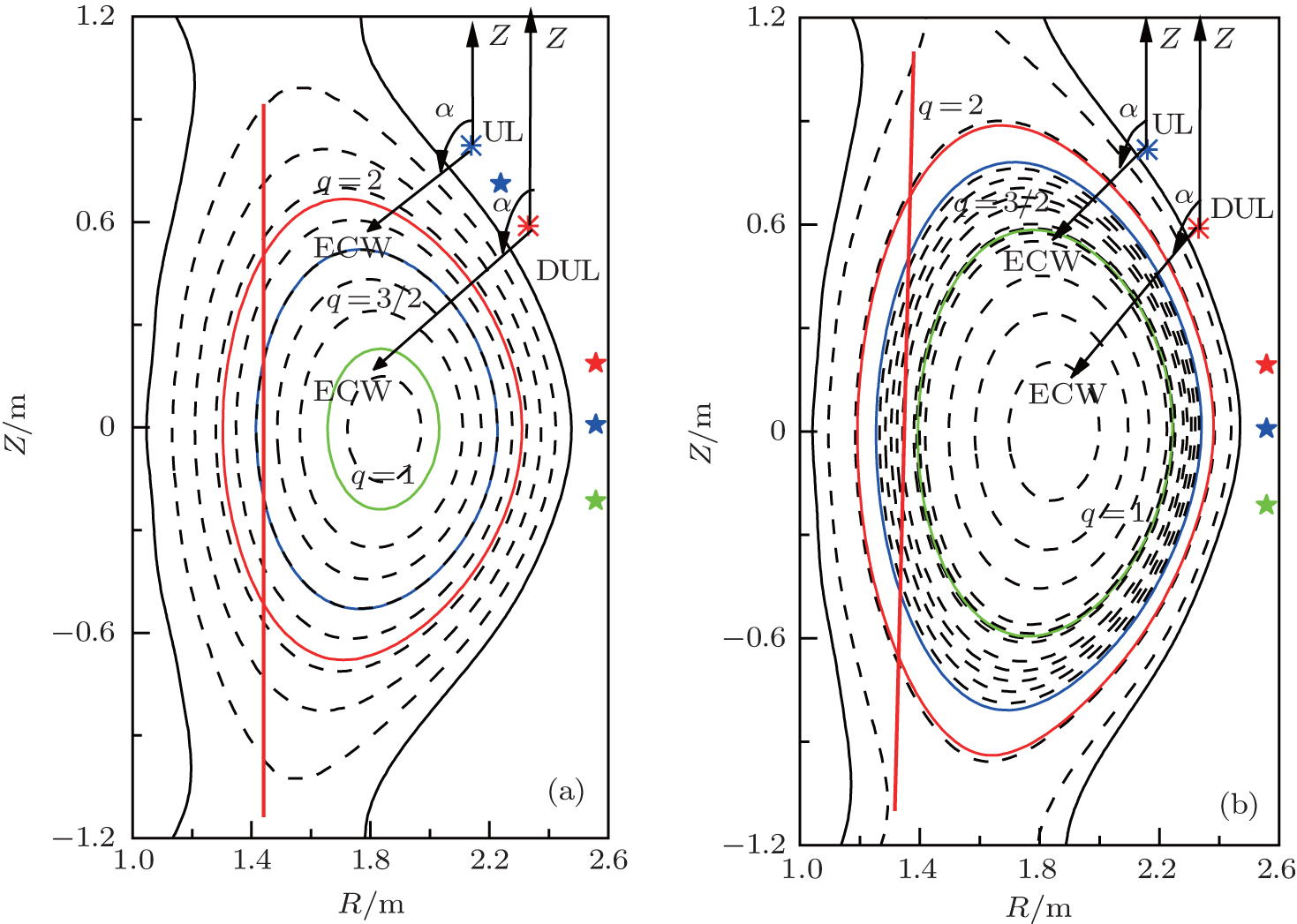
(a) HL-2M scenario SD1, with Ip = 1.2 MA, the three solid contours are the flux surfaces of q = 2, q = 3/2, and q = 1. The two asterisks indicate the locations of the upper (UL, R = 2.1 m, Z = 0.75 m) and the down upper (DUL, R = 2.3 m, Z = 0.55 m) launchers, respectively. The three pentagrams represent the locations of the top (R = 2.52 m, Z = 0.2 m), middle (R = 2.52 m, Z = 0.0), and bottom (R = 2.52 m, Z = −0.2) midplane launchers, respectively. (b) Scenario SD2, with Ip = 2.0 MA, the other parameters are the same as those for panel (a). The poloidal injection angle α and the resonance curves are marked in both panels. |
 , Dong Jia-Qi2, Wang Jun2, Yin Lan3