


Strongly enhanced flux pinning in the YBa2Cu3O7 − x films with the co-doping of BaTiO3 nanorod and Y2O3 nanoparticles at 65 K*
[Wang Hong-Yana), b) , Ding Fa-Zhu†a)  , Gu Hong-Wei†
a) , Zhang Tenga) ]
, Gu Hong-Wei†|
|


†Corresponding author. E-mail: dingfazhu@mail.iee.ac.cn
*Project supported by the National Natural Science Foundation of China (Grant No. 51272250), the National Basic Research Program of China (Grant No. 2011CBA00105), the National High Technology Research and Development Program of China (Grant No. 2014AA032702), and the Natural Science Foundation of Beijing, China (Grant No. 2152035).
YBa2Cu3O7 − x (YBCO) films with co-doping BaTiO3 (BTO) and Y2O3 nanostructures were prepared by metal organic deposition using trifluoroacetates (TFA-MOD). The properties of the BTO/Y2O3 co-doped YBCO films with different excess yttrium have been systematically studied by x-ray diffraction (XRD), Raman spectra, and scanning electron microscope (SEM). The optimized content of yttrium excess in the BTO/Y2O3 co-doped YBCO films is 10 mol.%, and the critical current density is as high as ∼17 mA/cm2 (self-field, 65 K) by the magnetic signal. In addition, the Y2Cu2O5 was formed when the content of yttrium excess increases to 24 mol.%, which may result in the deterioration of the superconducting properties and the microstructure. The unique combination of the different types of nanostructures of BTO and Y2O3 in the doped YBCO films, compared with the pure YBCO films and BTO doped YBCO films, enhances the critical current density ( JC) not only at the self-magnetic field, but also in the applied magnetic field.
Since the discovery of the YBa2Cu3O7 − x (YBCO) superconductor coated conductor, the promise of outstanding performances at temperature and magnetic field have fuelled a worldwide research investment.[1] Critical current density (JC) of the YBCO coated conductor is one of the important properties for the practical applications in superconducting magnets, generators, and motors.
There are complicated relationships existing between JC and crystalline defects in the YBCO matrix. Pinning force (FP) arises from the crystalline defects and depends on their size and shape, as well as on their composition and structural interaction in the YBCO matrix.[2] Some crystalline intrinsic defects in the YBCO superconducting films of many types, such as fine precipitates of non-superconducting phase, dislocations, vacancies, and grain boundaries, act as pinning centers.[3] However, those intrinsic defects could not provide enough pinning centers, especially in the magnetic fields. Therefore, it is necessary to introduce the artificial pinning centers (APCs) into the YBCO films. At present, a lot of attempts have been taken for the improvement of JC, such as substrate surface decoration, [4, 5] impurity addition, [6– 9] and RE addition or substitution.[10– 12] Among all of the solutions, impurity additions play an unmatched role, for being able to introduce APCs easily in a controlled manner. In 2007, Gutierrez et al. prepared YBCO films with BaZrO3 (BZO) addition by metalorganic deposition using trifluoroacetates (TFA-MOD).[9] Since then, the additions of Y2O3 nanoparticles, [13] and other perovskites compounds, such as BaSnO3(BSO), [14] BaHfO3, [15] and BaIrO3[16] nanoparticles have been extensively studied.
The APCs can be classified based on different criteria. One is to use the dimensionality of the defects. For example, BZO and BSO nanorods, the dislocations and columnar defects belong to 1D APCs; small angle grain boundaries are classified as two-dimensional APCs (2D-APCs); nanoparticles and second phases of the scale of ξ or more belong to 3D APCs, for example, Y2O3 nanoparticles.[17] The dimensionality of the APCs is the critical factor to achieve higher JC YBCO films. For years, the combinations of the different type of APCs in the YBCO matrix lead to a strong vortex-pinning landscape. The greatly enhanced JC was achieved to 6.5 mA/cm2 (77 K, self-field) for the YBCO films with the embedded BZO nanorods and BaTiO3 (BTO) nanostructures.[18] The combination of Y2O3 nanoparticles and BSO nanorods additions in the YBCO films has also been studied.[19] The JC for the Y2O3/BZO-doped YBCO thick films is as high as 4.3 mA/cm2 (75.6 K, self-field, 1.8 μ m).[20]
In this work, a new combination of the different type APCs (BTO-1D and Y2O3-3D) leading to a strong vortex pinning in YBCO films has been developed on the basis of easily scalable chemical solution deposition techniques. The molar content of BTO was 6% based on our previous work, [21] and that of yttrium excess was systematically studied by various means. In order to evaluate the effects of the amount of yttrium excess on critical properties and the microstructure in the doped YBCO films, we kept all the processing parameters constant and the molar contents of yttrium excess in the investigated YBCO films were different. This work is expected to find out the optimized content of yttrium excess in the BTO/Y2O3-doped YBCO films and discuss the effect of the amount of yttrium excess on the superconducting properties and microstructure.
The acetates of yttrium, barium, and copper and Ti acetylacetonate were dissolved in de-ionized water with an excess stoichiometric quantity of trifluoroacetic acid at room temperature to reach the starting solution. The contents of 6 mol% BTO and x mol% yttrium excess, with x ranging from 6% to 30% in the investigated YBCO films, were adjusted by controlling the Ti acetylacetonate and the acetates of yttrium in the solution, respectively. The extra acetate of barium was added to compensate the barium loss in the YBCO film and the moles ratio of the additional barium and Ti acetylacetonate is 1:1. The starting solution was refined under decompression, and then re-dissolved in methanol for further refining under decompression again to get the blue gel. Finally, the blue gel was dissolved in sufficient methanol to get the pure trifluoroacetate solution with a concentration of 2 mol/L.
Solution deposition was carried out by spin coating on 10 mm× 10 mm (00l)-oriented LaAlO3 (LAO) single-crystal substrates at 3000 r.p.m for 30 s to get the one side film on the substrate. Then the sample was put into a quartz tube within a horizontal furnace immediately. The coated films were calcined at the temperature up to 400 ° C in humidified oxygen. Then the calcined films were fired at 830 ° C in humidified Ar gas mixed with oxygen gas and finally oxygenated at 500 ° C for 90 min in a pure oxygen gas atmosphere.
The film thickness was determined to be ∼ 200 nm through the cross section micrograph taken by scan electron microscopy (SEM). Surface morphologies of YBCO films were also observed by SEM. The phase and texture of the as-grown film were characterized by x-ray diffraction (XRD) using Cu-Kα radiation (Bruker D8 Focus). X-ray ω -scan was carried out to evaluate the out-of-plane texture. μ -Raman measurements were carried out using the 532 nm line of an argon-ion laser at room temperature with a Via– Reflex Raman spectrometer, and all the Raman spectra were recorded at ambient temperature. The critical current density in the magnetic fields along the c axis of YBCO was determined from DC magnetization loops of rectangular samples by measurements on a physical property measurement system (PPMS) in a DC field up to 6 T. The JC values of the YBCO films in magnetic fields were determined by the bean critical state model formula, JC(H) = 20Δ M(H)/naba[1 − (a/3b)], where Δ M is the vertical width of the magnetization hysteresis (emu· cm− 3), and a and b (cm) are the cross-sectional dimensions of the sample perpendicular to the applied field (b ≥ a). The JC (77 K, self-field) was also measured by JC-scan Leipzig system.
Figure 1 shows the XRD θ – 2θ diffraction patterns for the samples with the yttrium excess amount ranging from 6 mol% to 30 mol%. It can be seen that all the major diffraction peaks are corresponding to the YBCO (00l) peaks, which indicates a well-textured, c-axis oriented YBCO grain structure. Moreover, there are three weak peaks at 2θ angles of 32.015° , 41.108° and 44.961° , which may be assigned to BTO (101), (203), and (200) peaks, respectively. In addition to the YBCO, the LAO and the BTO peaks, the Y2O3 (400) peak can be found in all the samples. In addition, we can observe that the peak assigned to Y2O3 (222) at 2θ angle of 28.978° , which begins to appear when the content of yttrium excess rises to 16 mol%. The XRD θ – 2θ diffraction patterns show that the yttrium excess is prior to form Y2O3 (400) orientation in the YBCO films, and Y2O3 (222) begin to form when the molar content of yttrium excess rises to 16%.
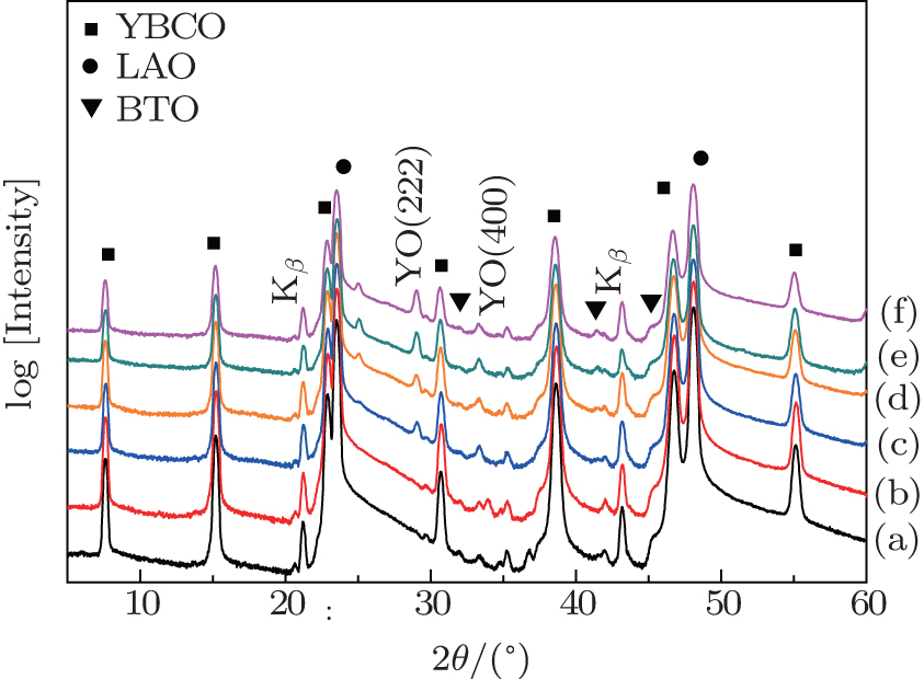 | Fig. 1. XRD θ – 2θ patterns of the BTO/Y2O3-doped YBCO films grown on LaAlO3 with several different contents of yttrium excess: (a) 6%, (b) 10%, (c) 16%, (d) 20%, (e) 24%, and (f) 30%. |
Considering that the lattice mismatch degree of cubic Y2O3 (lattice constant: 10.604 Å ) with the surrounding YBCO is ∼ 1.9% and that of the cubic BTO (3.999 Å ) is 4.4%, which may deteriorate the epitaxial growth of the YBCO on the LaAlO3 substrate. It is necessary to take all the samples to the x-ray ω -scan analyzing. The full width at half-maximum (FHWM) values for the YBCO (005) reflections are between 1.065° and 1.402° , and the minimum value belongs to the 10% yttrium excess sample, as listed in Table 1. The FWHM data indicates that all the YBCO films with different content of yttrium excess have a good out-of-orientation, and the addition of BTO and Y2O3 does not affect the YBCO epitaxial growth.
Table 1 also shows the self-field JC measured by JC-scan Leipzig system of the YBCO films with the different molar content of yttrium excess at 77 K. It can be clearly seen that there is a significant change of JC. The maximum JC value was obtained at the yttrium amount of 10 mol% yttrium excess, which is as high as 7.5 mA/cm2. With the increase in the amount of yttrium excess, the JC for the YBCO films begins to decrease sharply, which indicates that the size and density of the additional nanostructures existing in the doped YBCO samples are optimal when the molar content of yttrium excess is 10 mol%.
| Table 1. FWHM of (005) ω -scan and the critical current density of the BTO/Y2O3-doped YBCO films with several different contents of yttrium excess. The critical current density of 30% sample was undetected (u.d). |
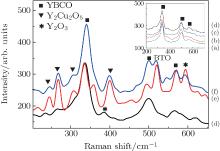
In order to further investigate the effect of the yttrium contents on the microstructures, the doped YBCO films with different contents of yttrium excess were applied to μ -Raman. Figure 2 shows the Raman spectra of the BTO/Y2O3-doped YBCO films with different contents of yttrium excess. There is no obvious difference between (a) 6%, (b) 10%, (c) 16%, and (d) 20% samples, and three peaks in these samples can be assigned to YBCO, as shown in the inner of Fig. 2. Meanwhile, the peak at 381 cm− 1 is assigned to Y2O3 of the 20% sample. However, some difference can be found when the content of yttrium excess rises to 24%, and there are some peaks at 240 cm− 1, 262 cm− 1, 303 cm− 1, and 394 cm− 1, which are assigned to Y2Cu2O5.[22] In addition, the peak at 515 cm− 1 is assigned to BTO[23] and 590 cm− 1 is assigned to Y2O3.[24] We speculated that the exceed yttrium reacts with copper, forming the Y2Cu2O5 phase, and the residual Barium reacts with Ti, forming the BaTiO3, which reinforces the strength of BTO μ -Raman peak when the content of yttrium rises to 24%. The formation of the Y2Cu2O5 phase is possible, which is the reason for the deterioration of the superconducting properties. The evolution of the microstructure can be observed from the SEM micrographs in Fig. 3. We find the deterioration of surface morphologies with the increasing content of yttrium excess. Some particles can be clearly observed to be distributed across the surface of the 10% yttrium excess sample, as shown in Fig. 3(b). With the increase of content of yttrium excess, the roughness surface is observed especially on the 24% sample in Fig. 3(e). The result is consistent with the Raman analysis, and the roughness may be caused by the formation of the Y2Cu2O5 phase. The EDS mapping of BTO/Y2O3-doped YBCO films with 30 mol% yttrium excess, which indicates the presence of exceeded Y and Ti within YBCO film (see Fig. 4).
 | Fig. 2. Raman spectra of the BTO/Y2O3-doped YBCO films with different contents of yttrium excess: (a) 6%, (b) 10%, (c) 16%, (d) 20%, (e) 24%, and (f) 30%. |
 | Fig. 3. SEM micrograph of the BTO/Y2O3-doped YBCO films with different contents of yttrium: (a) 6%, (b) 10%, (c) 16%, (d) 20%, (e) 24%, and (f) 30%. |
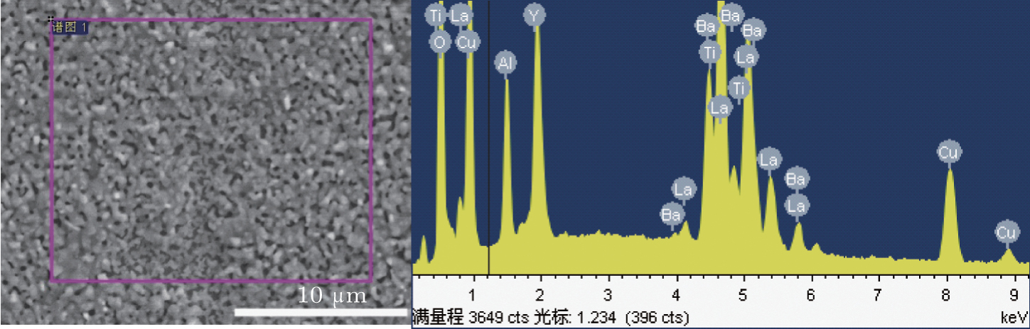 | Fig. 4. The EDS mapping of the BTO/Y2O3-doped YBCO films with 30 mol% yttrium excess. |
 | Fig. 5. (a) Critical current density versus magnetic field and (b) the pinning force versus magnetic field parallel to the c axis of the different doped YBCO films at different temperature. The pure YBCO film, BTO-doped YBCO film at 77 K, [18] and the 6 mol% BTO + 10 mol% yttrium excess doped YBCO at 77 K and 65 K. |
An extended investigation of the superconducting properties for the unique combining mode was taken by PPMS. Figure 5(a) shows the critical current density versus magnetic field, JC(H∥ c), at two typical temperatures (65 K and 77 K) measured by PPMS. Compared with the pure YBCO and BTO-doped YBCO films, [18] an overall increase in JC(H) of the 6 mol% BTO + 10 mol% yttrium excess doped YBCO film appears. In particular, the JC for the BTO + Y2O3-doped YBCO films is higher than 5 mA/cm2 below 0.1 T at 77 K, and the maximum JC value is close to 17 mA/cm2 at 65 K. The overall increase in JC at all magnetic fields can be more clearly seen from the magnetic-field dependence of the pinning force (FP = JC(H)), as shown in Fig. 5(b). We can find that the value of FP is as high as 24 GN· m− 3 for BTO+ Y2O3-doped YBCO films at 6 T (65 K).
In the early work by Ding et al.[18] BTO appeared as nanorods morphology in the matrix of YBCO. These BTO nanorods provided a strong flux pinning enhancement in YBCO films at 77 K. In this work, BTO nanorods act as 1D APCs and Y2O3 nanoparticles act as 3D APCs. Kaname and Paolo[17] have made a comparison of vortex pinning between nanorods and nanoparticles, and they found that the angular dependence of pinning energy of the nanoparticle is more gradual than that of the nanorod. Besides, the 
In this study, high-quality BTO/Y2O3-doped YBCO films were prepared by the TFA-MOD process. The optimized content of yttrium excess for the doped YBCO films was systematically studied and the YBCO films with 6 mol% BTO and 10 mol % yttrium excess have the maximum critical current density (JC) value of ∼ 17 mA/cm2 (65 K, 0 T) tested by the magnetic signal. Through systematic research, we found that not all the yttrium excess in the YBCO films turned into the Y2O3, and some yttrium excess reacted with copper, forming Y2Cu2O5 when the content of yttrium excess rises to 24 mol%, which may result in the deterioration of the superconducting properties and the microstructure. The superconducting properties of the YBCO films incorporated with BTO and Y2O3 nanostructures have a great dependence upon the content of yttrium excess. We hope that the results reported here explore a new way to enhance JC by chemical doping methods.
| 1 |
|
| 2 |
|
| 3 |
|
| 4 |
|
| 5 |
|
| 6 |
|
| 7 |
|
| 8 |
|
| 9 |
|
| 10 |
|
| 11 |
|
| 12 |
|
| 13 |
|
| 14 |
|
| 15 |
|
| 16 |
|
| 17 |
|
| 18 |
|
| 19 |
|
| 20 |
|
| 21 |
|
| 22 |
|
| 23 |
|
| 24 |
|
| 25 |
|
| 26 |
|