


Three-dimensional coherent diffraction imaging of Mie-scattering spheres by laser single-orientation measurement
[Zhang Jiana) , Fan Jia-Donga) , Zhang Jian-Huaa) , Sun Zhi-Bina) , Huang Qing-Jieb) , Jiang Huai-Dong†a)  ]
]
]
|
|


†Corresponding author. E-mail: hdjiang@sdu.edu.cn
*Project supported by the Major State Basic Research Development Program of China (Grant No. 2014CB910401) and the National Natural Science Foundation of China (Grant Nos. 31430031, 21390414, and U1332118).
Three-dimensional imaging with single orientation is a potential and novel technique. We successfully demonstrate that three-dimensional (3D) structure can be determined by a single orientation diffraction measurement for a phase object of double-layer Mie-scattering silica spheres on a Si3N4 membrane. Coherent diffraction pattern at high numerical aperture was acquired with an optical laser, and the oversampled pattern was projected from a planar detector onto the Ewald sphere. The double-layered spheres are reconstructed from the spherical diffraction pattern and a 2D curvature-corrected pattern, which improve convergence speed and stability of reconstruction.
Coherent diffraction microscopy is an important quantitative imaging technique to reveal and characterize microstructure in materials science and biology.[1] In combination with principles of optics, some new and modified methodologies based on coherent diffraction imaging (CDI) have emerged continuously.[2– 5] The basic principle of these techniques is that the oversampled coherent diffraction pattern from the object is measured and then directly phased to obtain an image with iterative algorithms. Since the first experimental demonstration, CDI has been applied to imaging a wide range of materials and biological specimens such as nanoparticles and cells by using synchrotron radiation and x-ray free electron lasers.[6– 10]
The 3D imaging is crucial to provide an insight into structure of matter. Up to now, to achieve the aim, acquiring multiple-orientation measurements or multiple thin section scanning is needed for traditional microscopy technologies.[11– 13] However, it is difficult to obtain simultaneously temporal and spatial information of samples by these 3D imaging schemes. For instance, when using an x-ray free electron laser, the sample will be damaged after a single shot.[14, 15] Recently, a new 3D imaging with single sample orientation has provided a promising approach to solve the problem.[16, 17] The basic principle of the imaging method is as follows: when a finite object is illuminated by a coherent beam, for a high numerical aperture microscope, a diffraction pattern on the Ewald sphere constitutes a 3D structure in Fourier space. If the oversampling satisfies 2 times of the Nyquist condition, the 3D image of the object could be reconstructed using an iterative phase retrieval algorithm. This technique has some advantages of investigating dynamic phenomena of materials, simplifying the process of getting experimental data. However, in comparison to the conventional CDI, 3D image reconstruction with this method becomes more challenging for larger and thicker objects.[17]
For high numerical aperture diffraction imaging with laser or soft x-ray, it is easy to achieve oversampled diffraction patterns with high signal-to-noise ratio at the CCD detector.[18, 19] As the CCD is a 2D planar detector, the solid angle subtended by each CCD pixel varies with the diffraction angle. From the center to the edge of CCD, the oversampling ratio of diffraction pattern is nonlinear. The diffraction pattern on the planar CCD is significantly distorted at high diffraction angles. To get linear oversampling and to remove the distortion, the diffraction pattern has to be projected onto the Ewald sphere for image reconstruction.[18] In this letter, we demonstrate 3D imaging of a double-layered phase object with a single orientation by optical laser diffraction. We suggested a combination of spherical diffraction pattern and 2D planar curvature-corrected diffraction pattern for 3D reconstruction, which could improve the stability and efficiency of reconstruction.
The coherent diffraction imaging experiment was carried out with a laser diffraction microscope, as shown in Fig. 1. A He– Ne laser with a wavelength of 543 nm (energy ∼ 1 mW, and divergence ∼ 1.5 mrad) was collimated by a compound lens system (lenses 1 and 2), which consists of two converging lenses with a 50 cm (lens 1) and 150 cm (lens 2) radius of curvature, respectively. Through the two converging lenses, a parallel beam was condensed with a diameter of ∼ 600 μ m. To ward off unnecessary scattering from the lenses, a couple of apertures were placed between and downstream of the lenses. A shutter of the CCD detector was mounted before the sample. To perform 3D imaging of a large phase object, we prepared a sample of double-layered silica spheres, which have wide applications in many fields such as atmospheric physics and oceanography.[20, 21]
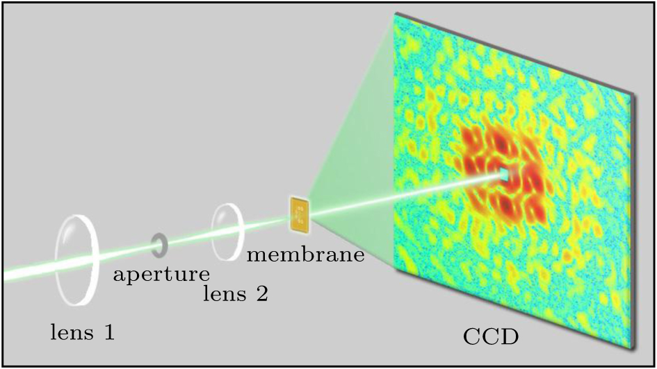 | Fig. 1. Schematic of a laser diffraction microscope. |
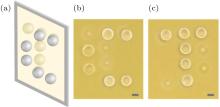
As shown in Fig. 2, the sample used for the image is on both sides of a 100-nm-thick Si3N4 membrane. A letter ‘ C’ , which is composed of six silica spheres, is supported on one side of the membrane. A letter ‘ T’ is on the other side of the membrane. Some spheres in two letters partially overlap and form a double layer structure, which can be observed in the optical micrographs (Figs. 2(b) and 2(c)). The transverse sizes of the sample is within 100 μ m and the thickness is about 32 μ m (each sphere has a diameter of about 16 μ m). The sample was mounted on a sample stage and illuminated by the laser beam. Coherent diffraction patterns from the sample were measured by a liquid-nitrogen-cooled CCD detector with pixel size of 20 μ m × 20 μ m in a 1300 × 1340 array. A beamstop was placed just in front of the CCD to block the direct beam. To achieve a good spatial resolution, the CCD was placed as close to the sample as possible, which increases the numerical aperture of the microscope. By optimizing experimental setup, the distance between the sample and the detector was reduced to 27 mm. To further enhance the spatial resolution, the CCD detector was moved both horizontally and vertically to acquire more data at a high angle position. Then all diffraction patterns were tiled together to form one high spatial resolution diffraction pattern. To obtain a small missing center (due to the beamstop), the CCD was moved downstream at a distance of 203 mm to the sample. Subsequently, low spatial resolution diffraction patterns were measured by moving the beamstop from first-quadrant to third-quadrant in order to further decrease the missing center. To remove the background scattering, we measured two sets of diffraction patterns at each position with and without the sample in the laser beam. The acquisition time for each sample pattern was 1 s/exposure with 300 exposures, and for each background pattern was about 1 s/exposure with 100 exposures. The high and low spatial resolution diffraction patterns after background subtraction were merged to one diffraction pattern of 2001 × 2001 pixels with a small missing center as shown in Fig. 3. Then the diffraction pattern was binned to a 501 × 501 array by numerically integrating 4 × 4 pixels into 1 pixel, which not only enhanced the signal-to-noise ratio of the diffraction intensity, but also expedited subsequent image reconstruction. To obtain a precise diffraction pattern, the binned diffraction intensity was then deconvolved.[22]
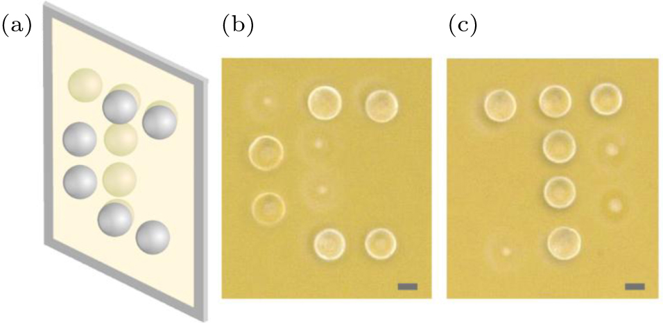 | Fig. 2. (a) Schematic of double-layer silica spheres on a Si3N4 membrane. Optical micrographs showing front (b) and back (c) views of the double-layered sample. The scale bars denote 10 μ m. |
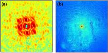
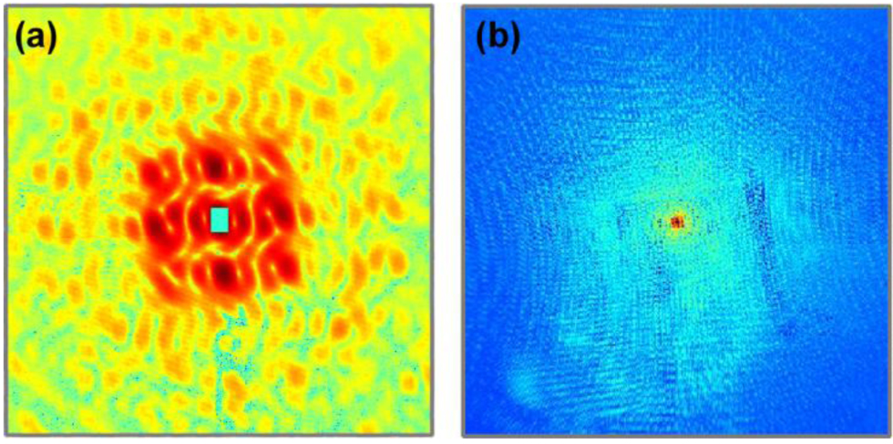 | Fig. 3. 2D diffraction patterns from the sample recorded by a planar CCD detector with low (a) and high (b) spatial resolution. |
Figure 3(b) shows the oversampled diffraction pattern with a diffraction angle of about 36.5° . At high angles, because the degree of oversampling is no longer the same as that of low angles (i.e., the approximation of sin θ ≈ θ is no longer valid), the diffraction pattern on the planar CCD will be distorted, which affects image reconstruction. To get linear oversampling and remove the distortion, according to previous study, [18] we interpolated the diffraction pattern from a plane onto a spherical surface. Figure 4(a) shows the planar diffraction pattern with 401 × 401 pixels after field curvature correction. Due to absorption and scattering of light by the sample of silica spheres, the diffraction pattern is non-centrosymmetric, resulting in the complex density of dielectric polarizability. To retrieve a 2D image of the sample from the curvature-corrected diffraction pattern, we used the hybrid input-output (HIO) algorithm together with a rectangular support. Figure 4(b) shows the magnitudes of the reconstructed image. The circle regions in the projected image represent silica spheres of the sample. Due to the double-layered structure of the sample, the regions indicated with white arrows correspond to the overlapped spheres, which is in excellent agreement with the optical micrographs shown in Fig. 2. However, the structure of the sample along the propagation direction of beam cannot be achieved from the 2D image.
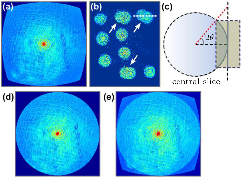 | Fig. 4. (a) 2D diffraction pattern after curvature correction. (b) 2D image reconstructed from (a). (c) Schematic of cross-section of a planar curvature-corrected diffraction pattern and spherical diffraction pattern on the Ewald sphere. (d) Front view of an oversampled diffraction pattern on the Ewald sphere. (e) Front view of curvature-corrected pattern and spherical diffraction pattern on a 3D Cartesian grid. |
In order to obtain a 3D image, according to previous studies, [16, 17] the planar diffraction pattern measured by CCD can be normalized and then projected onto the surface of the Ewald sphere on a 3D Cartesian grid. Figure 4(d) shows the front view of an oversampled diffraction pattern on the Ewald sphere. The array size of the 3D Cartesian grid is 401 × 401 × 135 voxels with a diffraction angle of 36.5° . Due to non-centrosymmetry of the diffraction intensity for the phase object, there is only one spherical pattern in the array. As the 3D imaging technique requires sufficient diffraction intensities with a large oversampling degree, reconstruction with only one single spherical pattern becomes more challenging for larger and thicker objects.
To obtain 3D reconstruction from limited data, additional constraints are needed to facilitate the reconstruction. According to our experience, enforcing an appropriate support, a region within which the sample image is confined, is important in 3D reconstruction. By using field curvature correction, 2D planar reconstruction provides a projection of the sample, which can form a cylindrical support along the beam direction and used as initial loose support for 3D reconstruction. In addition, based on the Fourier slice theorem, the 2D reconstructed projection corresponds to a Fourier slice through the center of 3D Fourier space of the object. According to the principle of conventional 3D CDI and tomography, [23] as shown in Fig. 4(c), one can build up a new 3D array in reciprocal space by combining the spherical diffraction pattern and the 2D planar diffraction pattern after curvature correction at the same sample orientation. Our numerical simulations have indicated that inserting the curvature-corrected pattern, as a strong constraint, significantly enhanced 3D reconstruction of larger objects and improved convergence speed. Figure 4(e) shows the front view of the curvature-corrected pattern and spherical diffraction pattern on a 3D Cartesian grid.
For 3D reconstruction of the sample, an iterative phase retrieval was carried out back and forth between reciprocal and real space with HIO algorithm. In real space, the voxel value outside the support and the negative voxel value inside the support were slowly pushed close to zero. In reciprocal space, the Fourier magnitudes on the Ewald sphere and the central slice remained the initial values in each iteration, and the other magnitudes were set as unknowns. After 1000 times iteration, we carefully used the shrink-wrap method to determine a new support by convolving the reconstruction.[24] For the large object, the convergence speed was slow. A final 3D reconstruction was obtained after 10000 iterations.
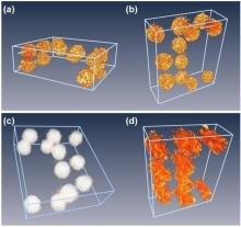
Figures 5(a)– 5(c) show the 3D reconstruction of amplitude and phase of the double-layered spheres from the diffraction pattern in Fig. 4(e). The 3D spatial resolution can be calculated from the diffraction pattern based on the geometrical construction and Bragg’ s law, which is determined by dX, Y = λ /sin(2θ ) and dZ = λ /(2sin2θ ), where λ is the wavelength, and 2θ is the diffraction angle.[16] In this experiment, the resolution along the direction perpendicular and parallel to the incident beam was estimated to be ∼ 0.9 μ m and ∼ 2.8 μ m, respectively. As shown in Figs. 5(a) and 5(b), the rendering of the 3D amplitude reconstruction indicates the double-layered spheres, which has excellent fidelity with the optical micrograph. The overlapped spheres with relatively low-amplitude values can be recognized. The changes in amplitude arise from the scattering and absorption of light. The reconstructed phase of the sample in Fig. 5(c) shows the same structure. Although there are still some differences between the current reconstructed image and the real object, the experimental error can be caused by the noise from CCD, optical path, and diffraction data processing. In order to evaluate the quality of the reconstructions, an error function Rerr can be defined by comparing amplitude of the measured and calculated diffraction patterns.[11] In addition, to compare the quality of reconstruction using this method, we performed another reconstruction of the sample from the spherical diffraction pattern alone in similar conditions. The result shown in Fig. 5(d), indicates that the 3D amplitude reconstruction is much worse and the doubled layer structure cannot be observed. To quantify the reconstruction, we performed line scans along the dashed lines across the two overlapped spheres in Fig. 5(a) (or Fig. 5(b)), and the corresponding spheres in the 2D reconstructed image (Fig. 4(b)). The results obtained are shown in Fig. 6. Region II (cyan) represents the overlapped area of the two spheres perpendicular to the direction of beam. Due to the oscillation of amplitude in Fig. 6(a), we calculated the average amplitudes of scan lines at different regions (the inset of Fig. 6(a)). In the overlapped region, the average amplitude is obviously lower than the other object regions. The amplitude changes are because of the absorption and scattering of light by the spheres. Figure 6(b) shows that the phase shift along the same dashed line is very small.
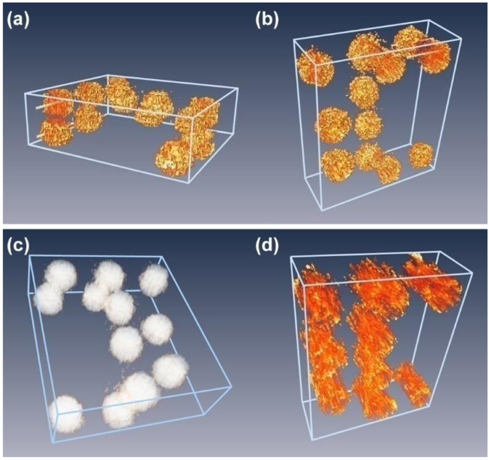 | Fig. 5. (a), (b) Rendering of 3D amplitude reconstruction of the double-layered spheres from the diffraction pattern in Fig. 4(e). (c) 3D phase reconstruction from the diffraction pattern in Fig. 4(e). (d) 3D amplitude reconstruction from the spherical diffraction pattern alone in Fig. 4(d). |
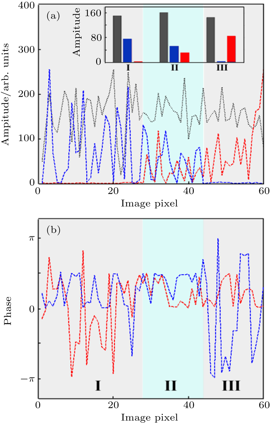 | Fig. 6. (a) Line scans along the dashed lines across two overlapped spheres in Figs. 5(a) and 5(b), and Fig. 4(b). The inset shows average amplitudes of scan lines at different regions. Region II (cyan) represents overlapped area of the two spheres perpendicular to the beam direction. (b) Two line scans along the same dashed line in the 3D phase reconstruction, showing the phase variation across the overlapped spheres. |
In summary, we experimentally demonstrated 3D imaging of a large phase object of double-layer Mie-scattering spheres with single-orientation optical laser diffraction. By using a combination of diffraction pattern on Ewald sphere and planar curvature-corrected diffraction pattern, the convergence speed and reliability of reconstruction can be significantly improved. With the strong constraint, the double-layered structure of the object was well reconstructed, which is in good agreement with the optical micrograph. This work provides a potential approach for investigating dynamic 3D structure of phase objects. With a large CCD or multiple CCD structure used for femtosecond light sources, detection of some temporal phenomena of materials and cells with high spatial resolution is feasible in future. In addition, optical lasers with different wavelengths and even soft x-ray can be used for this imaging technique, as long as diffraction patterns have small missing data and sufficient oversampling. Therefore, multiple-wavelength CDI experiments can be carried on in future to increase the amount of information in Fourier space and to further improve the quality of the reconstructed image.
| 1 |
|
| 2 |
|
| 3 |
|
| 4 |
|
| 5 |
|
| 6 |
|
| 7 |
|
| 8 |
|
| 9 |
|
| 10 |
|
| 11 |
|
| 12 |
|
| 13 |
|
| 14 |
|
| 15 |
|
| 16 |
|
| 17 |
|
| 18 |
|
| 19 |
|
| 20 |
|
| 21 |
|
| 22 |
|
| 23 |
|
| 24 |
|