

Water-assisted highly enhanced crystallographic etching of graphene by iron catalysts*
[Xue Lei-Jianga) , Yu Fangb) , Zhou Hai-Qingb)†  , Sun Lian-Feng
b)‡ ]
, Sun Lian-Feng]
|
|


†Corresponding author. E-mail: hqzhou0817@gmail.com
Corresponding author. E-mail: slf@nanoctr.cn
*Project supported by the National Natural Science Foundation of China (Grant No. 10774032) and the Instrument Developing Project of the Chinese Academy of Sciences (Grant No. Y2010031).
We report the assisted role of water vapor in crystallographic cutting of graphene via iron catalysts in reduced atmosphere. Without water, graphene can be tailored with smooth trenches composed of straight lines with angles of 60° or 120° between two adjacent trenches. After the addition of water, new chacteristics are found: such as almost no iron particles can be detected along the trenches; each trench becomes longer and lots of graphene nanoribbons can be generated. The underlying mechanism is proposed and discussed, which is attributed to stimulating and lengthening of the catalytic activity of iron particles by water vapor.
Graphene, which is a thin layer of graphite, has attracted a great deal of attention since it has great potential to be the candidate for future electronic circuits.[1– 3] Due to its special electronic band structures and high crystalline quality, [4– 6] the electronic properties, such as integer, room-temperature, fractional Hall effect and ballistic transport, have been well studied in detail. According to theoretical predictions, [7– 9] the electronic properties at the edge of graphene, especially graphene nanoribbons (GNRs) are related to the edge chirality of graphene (armchair or zigzag), which are also recently confirmed experimentally.[10, 11] For example, GNRs with zigzag edges can behave as a half-metal and be potentially applied as nanosized spintronic devices.[8] In contrast, GNRs with armchair edges can exhibit ribbon width-dependent metallic or semiconducting properties.[9] Although lots of experimental approaches have been applied to obtain GNRs, [12– 17] such as unzipping carbon nanotubes, [18] argon plasma etching[19] and lithium intercalation and exfoliation, [20] it is still challenging to experimentally control the edge chirality as irregular edge structures still exist at the graphene edge.[21, 22] Recently, via the catalytic hydrogenation of a graphene lattice, a thermally activated metallic nanoparticles-assisted etching process has been introduced to cut graphene or graphite into pieces with lots of trenches, [23– 26] or single-walled carbon nanotubes.[27] The obtained graphene edges are smooth and dominated by zigzag edges due to their being much more stable compared with armchair edges, [23] indicating the potential use of this method for fabricating GNRs.
During CVD (chemical vapor deposition) synthesis of carbon nanotube arrays, water vapor has been proven to be a catalyst activity enhancer and preserver to ensure nanotube continuous growth by removing the amorphous carbon coating the catalyst.[28, 29] This may imply that water vapor could have considerable effects on the graphene etching process. Therefore, it is highly desirable to study the role of water vapor in crystallographic etching of graphene, during which water can drive the thermally activated iron nanoparticles to be more active and/or extend the catalyst lifetime. In this work, the role of water is studied in graphite/graphene etching by mobile iron nanoparticles via catalytic hydrogenation of carbon. The catalytic graphite/graphene cuttings are performed under the same experimental conditions (temperature, pressure and reaction time) with and without water vapor. The two kinds of sample are studied and characterized after the etching experiments. It is found that compared to that without water vapor, water addition can result in several prominent changes in the etching results: longer trench, no detection of the iron particles along the trenches and lots of GNRs being fabricated. Based on these observations, we propose that water vapor can enhance and maintain the catalyst activity by etching away the carbon precipitate coating the iron catalyst.
Pristine graphene samples were obtained by micromechanical exfoliation of natural graphite (Alfa Aesar) by using transparent Scotch tape and then transferred onto Si substrates with a 300-nm SiO2 layer.[30, 31] Similar to the synthesis of single-walled carbon nanotubes, [32] a small amount of ferrocene (Fe(C2H5)2) powder was used as the iron source, which was loaded into an alumina boat upstream and close to the silicon substrate at the center of a tube furnace. To carry out the iron-catalyzed etching process with water and without water, we have introduced a three-step heating process under H2/Ar gas coflow (400 sccm/70 sccm, respectively) in the chamber. In order to deposit ferrocene onto the graphene surface, the center temperature was kept at 120 ° C for about one hour. Then the ferrocene-covered graphene samples were heated at 500 ° C for 30 min to decompose the ferrocene into isolated iron nanoparticles, which was followed by performing iron etching at 900 ° C for 15– 30 min. After thermal annealing, the samples were cooled down to room temperature in a hydrogen atomsphere. During the experiment, the addition of water is realized by flowing of Ar/H2 gas through the water in a conical flask.
In order to compare the role of water in the etching process, typical SEM images of the iron-etched graphene samples are shown in Fig. 1 in the absence and presence of water in the chamber. As can be seen from Fig. 1(a), individual iron nanoparticles usually run hundreds of nanometers to several micrometers along straight lines, leaving behind continuous etched trenches without the presence of water. Then these iron nanocatalysts are reflected from their straight path. What is interesting and surprising is that these reflections are regular with two adjacent trenches at an angle of either 60° or 120° (Fig. 1(a)). Since this angle is two or four times 30° , this implies that the trenches have the tendency to preserve the edge chirality and the cuts run along the same crystallographic orientation.[33, 34] This regularity has also been observed when water vapor is introduced during iron etching, which further confirms the appearance of regular trenches with the same edge chirality. A novel and new characteristic, which appears after the addition of water vapor, is that there are no iron nanoparticles at the end of any continuous trenches as shown in Fig. 1(b). This means that the water vapor should have some effects on the iron etching of graphite.
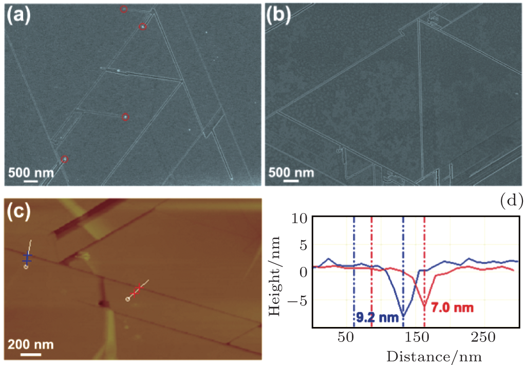 | Fig. 1. Turning of channels along the symmetry lines with angles of 120° or 60° in graphite at 900 ° C for 30 min by iron etching without (a) and with water addition (b). A typical AFM image (c) and height profiles (d) showing the etched nanotrenches on graphite without water addition. It is worth noting that almost no iron nanoparticles can be detected if some water vapor is introduced during the etching processs, for which the underlying mechanism is still not clear. |
Without water addition, every trench is usually composed of straight lines rather than irregular ones as shown in Figs. 1(a) and 1(c). The width and depth of each trench is related to the size of iron nanoparticles (Fig. 1(c)). Larger iron nanoparticles will result in wider and deeper nanotrenches (Fig. 1(d)). In our experiment, most of the nanoparticles are likely to change their moving direction if they come across a nanotrench that is already there which was etched by another nanoparticle. The etched trenches are very short and only a small amount of them can be as long as 1 μ m.[23– 25]
In sharp contrast, if some water is added in the etching process, new characteristics can be observed: first, no iron nanoparticles can be found on the trenches, along the trenches and at their ends (Fig. 1(b)). Second, even if there are step edges on the surface, which hinders the moving of nanoparticles, iron nanoparticles can move straight across these steps without changing direction, as shown in Fig. 2(a). This phenomenen is only observed with water addition and is clear evidence of the stimulation and ehancement of iron catalytic activity by water vapor. Third, longer nanotrenches can be found as shown in Figs. 2(b)– 2(d). These three SEM images were collected along the same nanotrenches, from which we can evaluate the relevant channel length up to 10 μ m. This indicates that the lifetime or etching speed of the iron catalyst has been lengthened due to the presence of water vapor, leading to longer trenches in graphite (Fig. 2(d)). Fourth, there are some nanotrenches that exhibit wave-like edges as indicated by the blue arrows in Figs. 2(c)– 2(d), for which the underlying mechanism is not clear. Fifth, the most striking feature resulting from water addition is easy fabrication of longer GNRs with lengths up to several micrometers attaching to thick graphene (Figs. 2(c), 2(d), and 3). In previous reports, GNRs are usually fabricated by e-beam lithography, or unzipping carbon nanotubes; the edges are not smooth and well controlled in edge configuration. These ribbons are located at the top of few-layer graphene, which are commensurate with the underlying graphene honeycomb lattice. Thus, it is interesting to design and construct device edges that are oriented with the underlying graphene crystal lattice, which needs further investigation. This is in contrast to conventional nanolithography or multistage cutting of graphite, which do not yield structures that are commensurate with the graphene lattice. Therefore, this technique via the catalytic hydrogenation of carbon shows the advantage of time saving, low cost and personal safety for the GNR fabrication. Although the exact mechansim is not clear at this moment, we propose a possible origin for this kind of ribbon formation in this way: upon high-temperature annealing in hydrogen atomsphere, iron nanoparticles etch graphene via the catalytic hydrogenation of carbon, where carbon atoms from exposed graphene edges dissociate into an iron nanoparticle, and then react with H2 at the iron surface. Due to the stimulation of water vapor on the catalytic activity of iron particles, the etching of graphite is much faster and longer trenches are obtained. Once there are two particles moving parrallel and close to each other as displayed in Figs. 2(b)– 2(d), narrow GNRs connected to large-sized thick graphene are easy to reach.
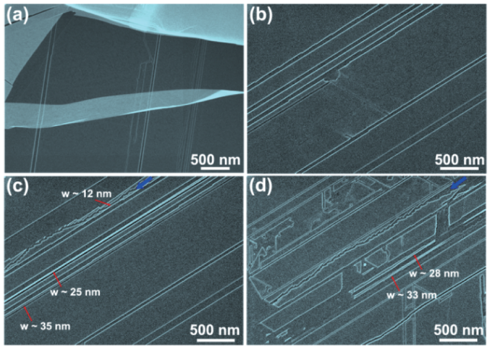 | Fig. 2. Typical SEM images showing some irregular channels and the creation of crystallographically oriented nanoribbons after iron etching with water addition. In panel (a), if there are step edges on the surface which hinder the moving of nanoparticles, iron nanoparticles can move straight across these steps without changing direction. Panels (b)— (d) are from the same nanotrenches, from which we can evaluate the relevant channel length up to 10 μ m. In these images, no iron catalysts are observed. |
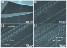
 | Fig. 3. Fabrication of crystallographically oriented nanoribbons with smooth edges and different widths after the addition of water vapor. (a) GNRs with width about 25– 58 nm. (b) The widths of GNRs can be as narrow as 10 nm, which can be potentially used as building components in field-effect transistors. |
One interesting and important question is how water can remove amorphous carbon coating iron catalysts. Water is reported to be a weak oxidizer that would selectively remove amorphous carbon during the growth of SWNTs.[28] This kind of coating of catalyst particles by amorphous carbon is one of the main reasons for the reduced activity and lifetime for catalyst particles. The addition of a small amount of water vapor can effectively enhance the activity of catalyst particles for the growth of SWNTs. Since the temperature in the etching of graphite/graphenes is similar to that for the growth of SWNTs, this suggests that the underlying mechanisms of removing amorphous carbon are similar to that for the growth of SWNTs. Meanwhile, it should be noted that the catalysts disappear after the etching experiment if water vapor is added, which may be due to the different atmosphere from that used in the growth of SWNTs and deserve more experimental works.
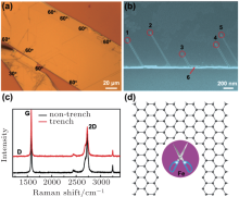
Figure 4(a) presents a typical optical image about the nanotrenches on a graphite after iron etching. From this figure, it can be seen clearly that the nanotrenches appear at graphite edges or terraced edges mainly with an angle of a multiple integer of 60° and very few 30° . This means that iron etching has the tendency to start at the edges. To confirm this statment, a controlled experiment is carried out by shortening the etching time to 1 min, and SEM is used to observe whether there are some trenches at graphene edges. Figure 4(b) shows an SEM image of the graphite edge after iron etching at 900 ° C for 1 min without water. Each trench has been labeled with digital numbers. It can be seen that the particles move and cut along symmetric directions as indicated in the trenches labeled “ 1” to “ 5” . It is obvious that all the straight trenches start from graphene edges with an angle of 60° toward the edge and are parrallel with each other, indicating that this single-particle etching shows good crystallographic orientation. Iron nanoparticles are always located at the end of each trench, which is consistent with that reported previously.[24, 25] Meanwhile, as can be seen in Fig. 4(b) that there is an angle transition between the trenches “ 3” and “ 6” with the angle at 120° , suggesting that the edge structures of these two nanotrenches remain the same (zigzag or armchair) although the nanoparticle is deflected by the graphene edge. Thus, regarding the parrallel straight lines from “ 1” to “ 5” and 120° turn between trenches “ 3” and “ 6” , it is reasonable to draw the conclusion that the channels are cut along similar crystallographical orientations.
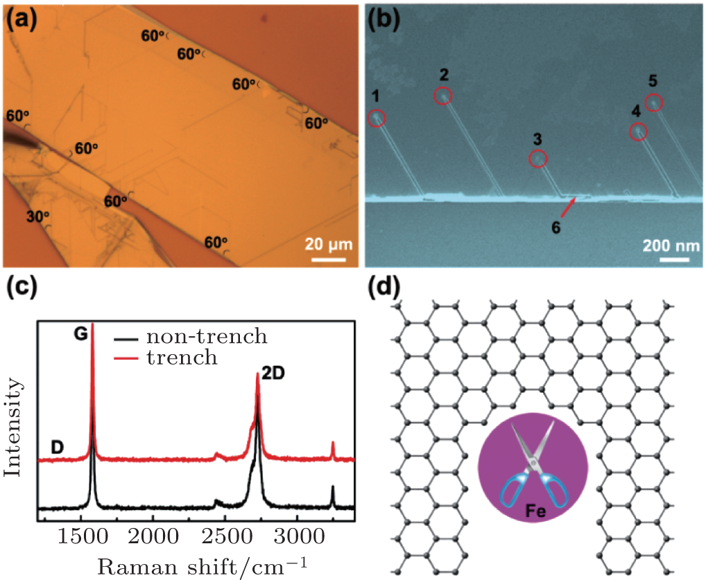 | Fig. 4. Nanocutting of graphene by iron catalysts: (a) Experimental visulisation of the nanotrenches at graphite edges by an optical microscope. (b) SEM image of nanotrenches at a graphite edge by changing the etching time to 1 min. It is noted that the cutting tends to start at graphene step edges with angles of 60° and the nanoparticles can be found at the end of the nanotrenches. (c) Raman spectra collected on graphite without (black) and with (red) nanotrenches. (d) Schematic of the crystallographic graphite etching process. As the catalyst directly contacts the graphene edges, it would react with the corresponding active carbon atoms, move forward and break the carbon-carbon bonds in graphene along specific crystallographic directions. |
According to Raman spectra at graphene edges, when the angles between two graphene edges are 60° or 120° , these two edges should exhibit similar edge chirality.[33, 34] When the angles are an odd integer multiple of 30° between two edges, these two edges should have different edge structures: one is zigzag, the other is armchair. An interesting question here is which one of the edge structures (armchair or zigzag) is energetically favorable during iron etching? From the Raman spectra of these nanotrenches, almost no D peak is observed, as shown in Fig. 4(c), suggesting that the edge structure of the etched trench is mainly composed of zigzag edges.[33, 34] It should be noted that according to theoretical calculations, [23, 35] the zigzag edge is much more stable than the armchair one. This means that the carbon atoms from a armchair edge are much easier to be disolved by iron nanoparticles than those from a zigzag edge, thus leaving the zigzag edge at the etched trench as shown in Fig. 4(d). In this schematic, as the iron nanoparticles diffuse onto the edges of graphene, the corresponding active carbon atoms dissociate on the iron catalyst, and then react with hydrogen on its surface. The moving iron nanoparticles remove carbon atoms in the graphene along tracks aligned with the underlying crystal lattice, forming the observed nanotrenches. As shown in Fig. 4(b), the etched trenches start from the graphite edges with the cutting direction at an angle of 60° or 120° with the edges, and each iron nanoparticle is found at the end of each trench. This reaction is based on catalytic hydrogenation of carbon, [36, 37] in which graphene acts as the carbon source. In this case, the deactivation of the iron catalyst readily occurs due to carbon coating at its surface. If some water vapor is introduced during graphene etching, the role of water is to remove this kind of carbon coating and revive the catalyst activity. This means that the iron catalysts can have longer movements and heavier etching in graphite, resulting in longer nanotrench or nanoribbon formation.
In summary, the role of water vapor is investigated in crystallographic and anisotropic etching of graphene/graphite in this work. The addition of water can enhance the reactivity of catalyst by removing coating amorphous carbon. Meanwhile, GNRs as narrow as 10 nm with the length up to several micrometers can be obtained, which has great potential in improving the performance of the field-effect transistors based on GNRs.
| 1 |
|
| 2 |
|
| 3 |
|
| 4 |
|
| 5 |
|
| 6 |
|
| 7 |
|
| 8 |
|
| 9 |
|
| 10 |
|
| 11 |
|
| 12 |
|
| 13 |
|
| 14 |
|
| 15 |
|
| 16 |
|
| 17 |
|
| 18 |
|
| 19 |
|
| 20 |
|
| 21 |
|
| 22 |
|
| 23 |
|
| 24 |
|
| 25 |
|
| 26 |
|
| 27 |
|
| 28 |
|
| 29 |
|
| 30 |
|
| 31 |
|
| 32 |
|
| 33 |
|
| 34 |
|
| 35 |
|
| 36 |
|
| 37 |
|