


Adiabatic quantum pump in a zigzag graphene nanoribbon junction*
[Zhang Lin ]
]
]
|
|


†Corresponding author. E-mail: lzhang2010@163.com
*Project supported by the National Natural Science Foundation of China (Grant No. 110704033), the Natural Science Foundation of Jiangsu Province, China (Grant No. BK2010416), and the Natural Science Foundation for Colleges and Universities in Jiangsu Province, China (Grant No. 13KJB140005).
The adiabatic electron transport is theoretically studied in a zigzag graphene nanoribbon (ZGNR) junction with two time-dependent pumping electric fields. By modeling a ZGNR p–n junction and applying the Keldysh Green’s function method, we find that a pumped charge current is flowing in the device at a zero external bias, which mainly comes from the photon-assisted tunneling process and the valley selection rule in an even-chain ZGNR junction. The pumped charge current and its ON and OFF states can be efficiently modulated by changing the system parameters such as the pumping frequency, the pumping phase difference, and the Fermi level. A ferromagnetic ZGNR device is also studied to generate a pure spin current and a fully polarized spin current due to the combined spin pump effect and the valley valve effect. Our finding might pave the way to manipulate the degree of freedom of electrons in a graphene-based electronic device.
Graphene, a monolayer of carbon atoms packed into a two-dimensional honeycomb lattice, has been intensively studied since its birth in 2004.[1– 10] The low-energy carriers in graphene have a linear energy– momentum dispersion around the Dirac zero points, [3, 4] which can be well described as a massless Dirac fermion. Due to its unique energy band structure, graphene has various extraordinary electron transport properties, [5– 10] such as long spin coherent length, [5] high carrier mobility, [6] and gate voltage-controllable electron transport.[7, 8] Different from the traditional semiconductor material, the quasi-particle in graphene not only has the space and spin degrees of freedom, but also has a new valley degree of freedom, [11] corresponding to the two inequivalent valleys K and K’ at the corners of the Brillouin zone. The valley degree of freedom is energy-degenerate and satisfies the time-reversal symmetry, its physical properties are similar to those of the electron’ s spin, so it is also called pseudo-spin in real space. The valley degree of freedom of an electron in graphene can be used to manufacture multi-functional valley electronics in future.[11, 12]
The earliest research of valley-dependent electron transport explored the valley valve effect in zigzag graphene nanoribbons (ZGNRs).[12– 14] Soon after the birth of graphene, Rycerz et al.[12] proposed a ZGNR valley filter, they found that electron transport can be completely suppressed in a nonmagnetic ZGNR p– n junction by modulating the gate voltage, and inferred that this phenomenon may come from the intrinsic inter-valley electron scattering between the different ZGNR regions. Subsequently, Cresti et al.[13] and Nakabayashi et al.[14] confirmed the existence of the valley valve effect, and revealed that the valley switching effect can only exist in an even-chain ZGNR junction. Recently, the valley valve effect in the ferromagnetic ZGNR junction was widely utilized to generate, separate, and detect a fully spin-polarized electron.[15– 20] For example, Chen et al.[15] reported the magneto-resistance phenomenon in an even-chain ZGNR ferromagnetic junction, and found that the tunneling junction can serve as a perfect spin filter. Wang et al.[16] proposed a magnetic ZGNR junction to separate and detect a 100% spin-polarized current in real space.
Although there were many works focusing on the spin transport in armchair graphene nanoribbon (AGNR) junctions, [21– 23] the valley valve effect has not been investigated in AGNRs so far. For instance, Zhou et al.[22] reported the current-induced spin transfer torque in a ferromagnetic AGNR junction. In a recent work, a pure spin current was predicted in an AGNR spin pump, [23] which is attributed to the asymmetry of the AGNR junction rather than the valley valve effect. The valley valve effect is one of the intrinsic properties of the ZGNR junctions, and it crucially relies on the zigzag-chain number N for the zero-energy transport mode: when N is even, the electron wave function has a definite even or odd pseudo-parity, corresponding to the mirror symmetry of the ribbon. The quasi-particle transport in an even-chain ZGNR junction meets the pseudo-parity conservation or so-called valley selection rule, that is, only the carrier with the same pseudo-parity can pass through the ZGNR junction, otherwise the valley current is blocked. Oppositely, the valley valve effect can not appear in an anti-zigzag graphene junction when N is odd, for the pseudo-parity conservation of the quasi-particle is broken.
Since the pseudo-parity of the quasi-particle exhibits high controllability in a steady graphene system, the previous literature[24– 28] on the valley valve effect were mainly focusing on the equilibrium ZGNR junctions, and whether the valley valve effect would be affected by an unsteady quantum pump has not been investigated yet. Thus in this work, we propose an even-chain ZGNR p– n junction to study the valley valve effect in a time-dependent quantum pump. By using the Keldysh Green’ s method, we found that the valley valve effect could still exist and crucially rely on the pumping frequency, because the pseudo-parity of particle could be changed by absorbing or emitting a photon energy ħ ω in a photon-assisted tunneling process, which would allow or forbid an electron flowing through the ZGNR junction. A ferromagnetic ZGNR junction is also studied to produce a pure spin current and a 100% polarized spin current by using the interplay between the valley valve effect and the photon-assisted spin pump approximation.
The rest of this paper is arranged as follows. In Section 2, we theoretically propose an adiabatic quantum pump based on an even-chain ZGNR junction, and derive the general formulae for time-averaged current of the device. In Section 3, we present numerical results to investigate the frequency-controllable electron transport under the valley valve effect and the quantum pump effect in the ZGNR junction. Finally, a concise conclusion of our investigations is drawn in Section 4.
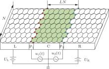
We consider an adiabatic ZGNR quantum pump as shown in Fig. 1, where two time-dependent electric fields are applied on two edges of the un-doped C ZGNR region. The left (L), and the right (R) ZGNRs are two p(n)-doped or ferromagnetic leads with controllable potentials UL(R). The width of device is denoted by the zigzag-chain number N, the length of the C region is LNa with the lattice constant a = 2.46 Å . In the tight-binding lattice model, the system’ s Hamiltonian is given by
 |
the above Hamiltonian is divided into two parts H0 and H1. Here, H0 represents the ZGNR device in the absence of pumping fields, 
 | Fig. 1. Schematic diagram of an adiabatic quantum pump based on a ZGNR junction. The middle C region is an un-doped ZGNR with two time-dependent pumping fields u1(t) and u2(t) asymmetrically applied on the boundaries P1 and P2, respectively. The left (L) and the right (R) ZGNRs are two semi-infinite p(n)-doped or ferromagnetic leads with two controllable gate voltages UL and UR. The width of the ZGNR is described by the zigzag-chain number N, and the length of the C region is denoted by LN. |
Now, we derive a general formula of the average spin-dependent current flowing through the left ZGNR lead. The spin-resolved currents can be obtained from the Heisenberg equation of motion,

where NLσ is the spin-resolved electron number operator in the left lead. By using the Keldysh Green’ s function formula, [30, 31] the average pumped current in the device can be expressed as
 |
where T = 2π /ω is the period of pumping cycle, the trace Tr sums all the transverse lattice i of the C region, 
 |
where the integrand range has been extended to [− NT, NT] with N → ∞ , we can simplify Eq. (3) with the fact that 
 |
where Γ Lσ is line-width function of the left ZGNR lead. To calculate the average pumped current in Eq. (4), we need calculate the Keldysh Green’ s function Gr, a, < in the presence of pumping potential fields, and consider the time-dependent potentials vi(t) with a finite frequency as a perturbation term. The Keldysh Green’ s function can also be expanded by means of the Dyson equation
 |
which can be abbreviated as a matrix form Gk = Gk0 + Gk0VkGk0 + ⋯ , where the Keldysh Green’ s function Gk is defined as a 2 × 2 dimensional matrix[32, 33]
 |
where 

 |
Because the device is under a zero external bias, the unperturbed Green’ s function Gk0 cannot produce any charge current without the pumping fields. The first-order perturbed term Gk1 is also found not to yield a steady nonzero charge current in our calculations, thus Gk2 can be regarded as the lowest-order correction to generate a pumped current. Due to the Dyson equation and the Langreth theorem, [32, 33]
 |
where 
 |
where HC is the unperturbed Hamiltonian of the C ZGNR region, and I is a unit matrix. The effects of two semi-infinite ZGNR leads are incorporated into two self-energy terms 
Finally, with the relations 
 |
 |
where 

In this section, we shall present the numerical results of pumped charge current ILR = ILR↑ + ILR↓ or spin-dependent current ILRσ in a ZGNR p– n junction and ferromagnetic junction influenced by an adiabatic quantum pump. In our calculations, the zero temperature limit (T = 0 K) is taken, only the even-chain ZGNR is considered, N = 4. The left and the right ZGNR terminals have the same potential amplitude | UL| = | UR| = U = 0.1 eV. For a ferromagnetic junction, two ZGNR leads have the same magnetization magnitude h and different magnetization angle θ L(R) along the z axis. The middle C ZGNR is un-doped and its on-site energy is set as the zero energy reference UC = 0 eV, the length of the C region is fixed LN = 20. The amplitudes of two pumping potentials are set to equal V0 = 1 eV. It should be noted that the photon energy and the pumping frequency have the same energy unit ħ ω in our calculations.
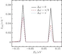
In Fig. 2, we calculate ILR versus EF with different pumping phase difference Δ φ in a ZGNR p– n junction at a zero external bias. When the left and the right ZGNR leads have the opposite p-doped and n-doped in Fig. 2, due to the spatial inversion asymmetry and single-photon-assisted tunneling process, a sizable pumped charge current could appear in the vicinity of EF = ± U, and no current emerges when EF is outside two pumping regions [− U − ħ ω , − U + ħ ω ] and [U − ħ ω , U + ħ ω ], respectively. The widths of two resonance charge currents in the pumping regions are approximately equal to 2ħ ω , corresponding to the transmission electron interacting with the pumping fields by absorbing or emitting a photon ± ħ ω . Additionally, the magnitudes of the two pumped charge currents are asymmetric functions of EF and the pumping phase difference Δ φ , owing to the fact that the electron– hole inversion antisymmetry is slightly broken by the Fermi level and the pumping phase difference.
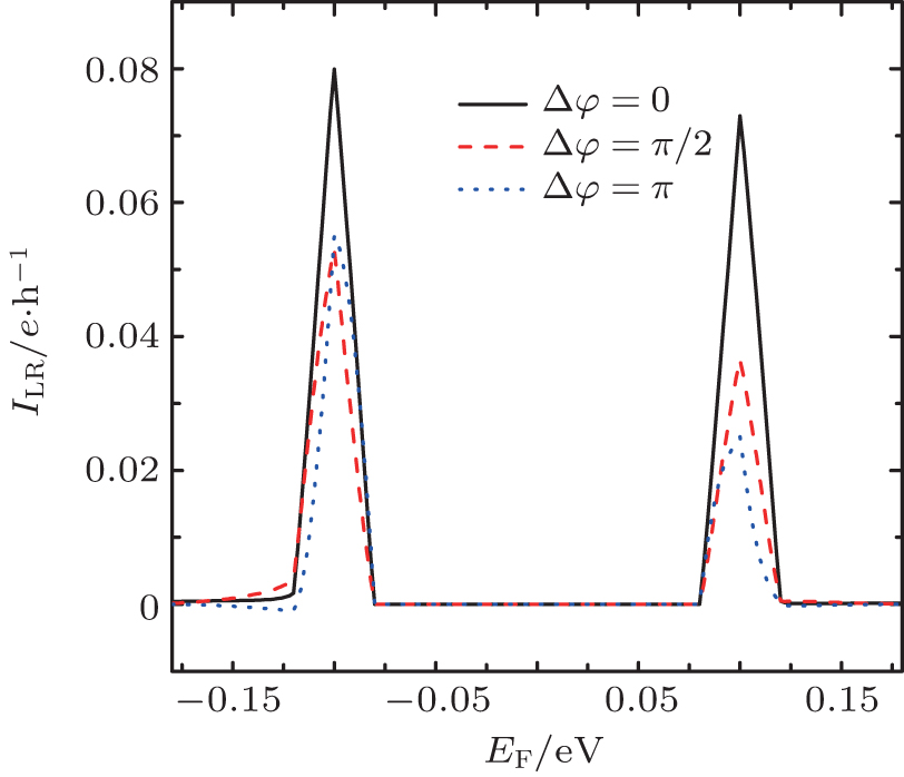 | Fig. 2. The pumped charge current ILR versus Fermi level EF for different pumping phase difference Δ φ in a ZGNR p– n junction. The on-site energies of the left, the middle, and the right ZGNRs are UL = 0.1 eV, UC = 0.0 eV, UR = − 0.1 eV, respectively. The pumping frequency is set to ħ ω = 0.02 eV. |
To reveal the pumped charge current in the ZGNR p– n junction in Fig. 2, we draw the lowest-energy transport modes of the left, the C, and the right ZGNRs in the momentum-space in Fig. 3. The p(n)-doped energy bands of the left (right) terminals are asymmetric compared with that of the un-doped C region, which may cause the electrons and holes in the three ZGNR regions to have the opposite even (“ + ” ) and odd (“ − ” ) pseudo-parities near the Fermi level. When − U + ħ ω < EF < U − ħ ω , the single-photon-assisted energy exchange EF ± ħ ω is too small to open the tunneling transport process, thus it cannot generate a charge current in Fig. 2. When EF is increased or decreased to the two pumping regions ± U − ħ ω ≤ EF ≤ ± U + ħ ω , the transmitted electron in the three ZGNRs could have the same pseudo-parity by obtaining or losing a photon energy ħ ω , and electron transport is allowed due to the valley selection rule. Furthermore, the photon-absorption process and its converse photon-release process are asymmetric in the pumping regions, which can cause two asymmetric pumped currents in Fig. 2. Similarly, no charge current can be pumped out at EF ≪ − U − ħ ω or EF ≫ U + ħ ω .
 | Fig. 3. Energy– momentum dispersion of zero-energy edge states of the left (p-doped), C (un-doped), and right (n-doped) ZGNRs in the p– n junction. The “ + (− )” represents the even (odd) pseudo-parity of the edge mode, and it could be different for the conduction band (solid line) and the valence band (dashed line). The arrows show the electron transport owing to the valley selection rule. The shaded areas around ± U are two pumping regions for producing nonzero charge currents. |
A frequency-controllable current valve is taken into account in a ZGNR p– n junction based on the photon-assisted tunneling process and the valley selection rule. Figure 4 describes ILR versus EF for different pumping frequency ħ ω in the ZGNR p– n junction. As previously mentioned, no charge current can emerge at − U + ħ ω < EF < U − ħ ω , the tunneling transport process is always closed (ILR = 0) due to the valley selection rule. The current blocking region − U + ħ ω < EF < U − ħ ω is crucially dependent on the pumping frequency, in other words, the current pumping region is frequency-adjustable. For example, when the pumping frequency is increasing, the amplitude of current is increased rapidly, while the current blocking region is conversely decreased as shown in Fig. 4. When ω ≥ U, there is no current blocking phenomenon at − U + ħ ω < EF < U − ħ ω , the whole energy regions are allowed for the pumped current, this phenomenon is similar to that of the odd-chain ZGNR junction.[13, 14]
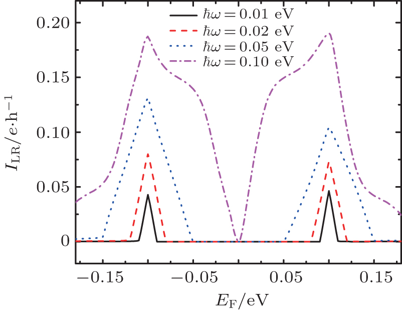 | Fig. 4. The ILR is a function of EF with different pumping frequency ħ ω in a ZGNR p– n junction, the pumping phase difference is fixed Δ φ = π /2. The other parameters are the same as Fig. 2. |
In Fig. 5, we investigate the frequency-controllable charge current ILR versus pumping frequency ħ ω for different phase difference Δ φ in the ZGNR p– n junction. As it is shown, there is a critical frequency ħ ω c = U − EF to produce a pumped current. When the pumping frequency is small ω < ω c, due to the valley valve effect and the photon-assisted tunneling process, the quasi-particles have the opposite pseudo-parities and cannot obtain sufficient energy to change their pseudo-parities, therefore the pumped current is blocked, ILR = 0. When the pumping frequency is large enough ω ≥ ω c, a nonzero pumped current comes into being and increases rapidly with the pumping frequency. As shown in the inset of Fig. 5, at the adiabatic limit and | ω – ω c| ≪ 1, the pumped current is a linear function of the frequency regardless of the pumping phase difference, ILR ∝ ω , which is an important feature of the lowest-order quantum pump approximation.[36]
 | Fig. 5. The ILR versus ħ ω in a ZGNR p– n junction. The Fermi level is set as EF = 0.05 eV, The other parameters are the same as that in Fig. 2. The inner panel describes the charge current versus ħ ω around the critical frequency ħ ω c = 0.05 eV. |
Since spin-dependent energy band splitting in a ZGNR ferromagnetic junction can also cause the pseudo-parity asymmetry of the quasi-particle, we propose a ZGNR ferromagnetic function to produce a pure spin current and a completely polarized spin current due to the spin pump effect and the valley selection rule. Unlike the left and right ZGNR leads that have the opposite pseudo-parities in the p– n junction, the pseudo-parities of two ferromagnetic ZGNR leads rely on the local magnetization orientations.
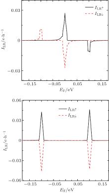
In Fig. 6, we present the spin-resolved current ILRσ versus EF for different magnetization configuration in a ZGNR ferromagnetic junction. When the left and the right ferromagnetic leads have the same magnetization direction θ L = θ R = 0 in Fig. 6(a), the spin up (down) energy bands of the leads have the same pseudo-parities. Due to the spin pump effect and the valley valve effect, there are three pumping regions to generate the spin currents. The first one is in the vicinity of EF = 0, a spin up electron could absorb a photon to yield a spin up tunneling current ILR↑ , while a spin down hole only generates an opposite direction current ILR↓ by emitting a photon. Hence, the pumped spin currents are antisymmetric, ILR↑ = − ILR↓ , and they can form a pure spin current JLR ≡ ILR↑ − ILR↓ ≠ 0 without accompanying any charge current ILR ≡ ILR↑ + ILR ↓ = 0 at EF = 0. The second and the third regions are at EF = ± h, only one spin-species current is nonzero, the other one is completely suppressed, therefore, two completely polarized spin currents can be pumped out, i.e., ILR↓ ≠ 0 and ILR↑ = 0 at EF = − h; ILR↑ ≠ 0 and ILR↓ = 0 at EF = h. In addition, the directions and the polarization degrees p = (ILR↑ − ILR↓ )/(ILR↑ + ILR↓ ) = ± 100% of two fully-polarized spin currents are opposite, which can be changed by EF and other system parameters easily, so the proposed ZGNR ferromagnetic junction can be designed as a dual-channel spin filter.
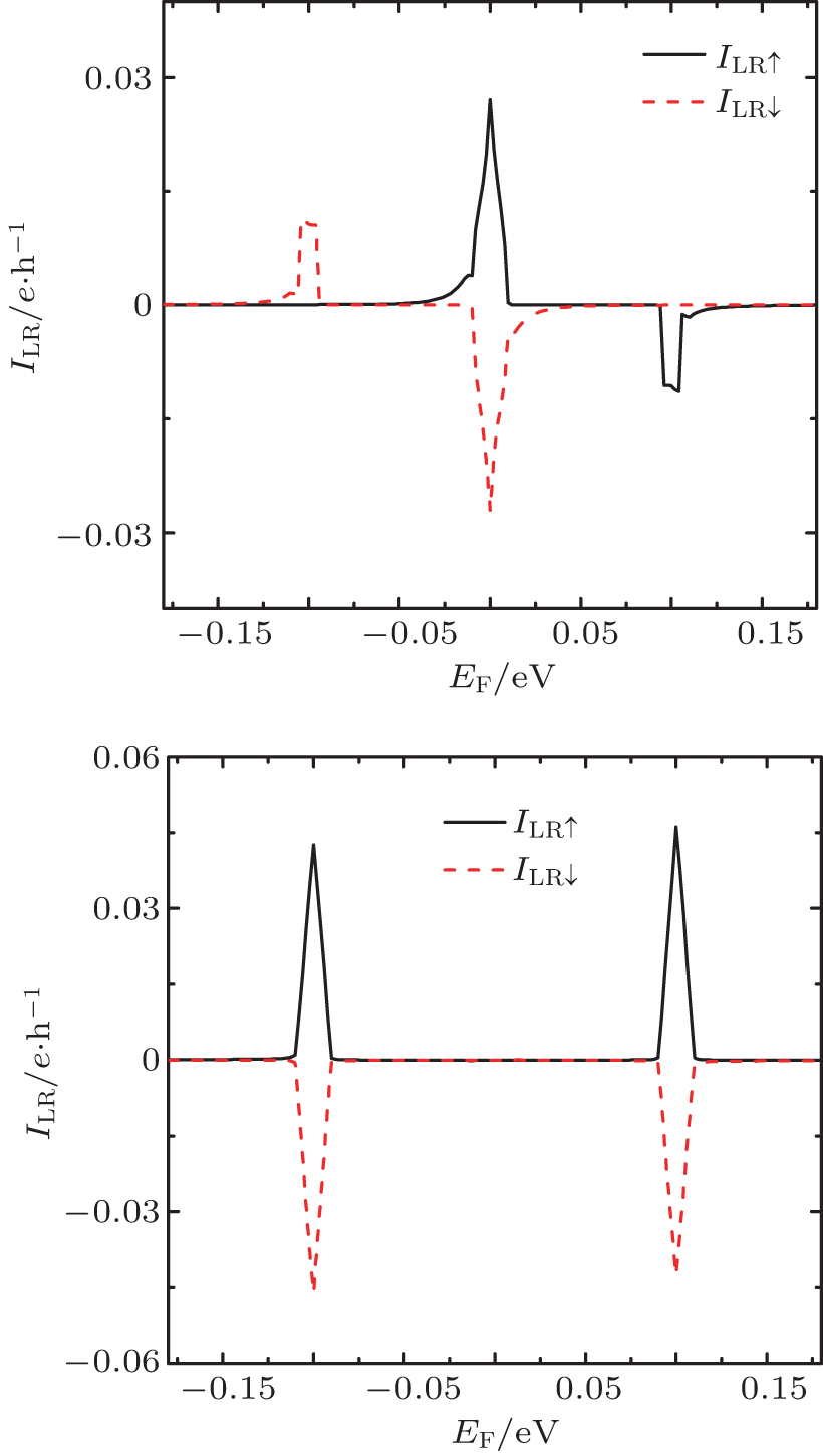 | Fig. 6. Spin-dependent current ILRσ versus EF in a ZGNR ferromagnetic junction for different magnetization configurations: (a) θ L = θ R = 0 and (b) θ L = 0, θ R = π . The other parameters are set as follows: the on-site potentials of the left, middle, and right ZGNRs are UL = UC = UR = 0.0 eV, the pumping frequency and phase difference are ħ ω = 0.01 eV and Δ φ = 0, respectively. |
The spin-dependent current ILRσ is presented in Fig. 6(b) as the function of EF in an antiparallel magnetization ZGNR junction, θ L = 0 and θ R = π . Because the spin-resolved energy bands and the pseudo-parities of the left and the right electrodes are opposite to those in Fig. 6(a), the antiparallel magnetization ZGNR junction cannot generate a pure spin current around EF = 0. At EF = ± h, two approximate pure spin currents instead of complete polarization spin currents are pumped out in the antiparallel magnetization ZGNR junction. The pumped spin up and spin down currents are antisymmetric functions of the Fermi level, i.e., ILR↑ (EF) = − ILR↓ (− EF). Because it is difficult to separate and detect the pure spin current in the present experiments, this antiparallel magnetization ZGNR junction may act as a pure spin current generator and detector, approximately.
In summary, we have studied the adiabatic electron transport in a ZGNR p– n (ferromagnetic) junction with two time-dependent pumping potentials. It was found that a nonzero charge current can be generated in the ZGNR junction at a zero bias, which is attributed to the interaction between the photon-assisted tunneling process and the peculiar valley selection rule in the even-chain ZGNR junction. By varying the system parameters such as the pumping frequency, the Fermi level, and the magnetization orientation, etc., not only the magnitude but also the ON and OFF states of the pumped current can be modulated. This reveals that a ZGNR p– n junction with the pumping potentials can act as a frequency-adjustable current filter. A ferromagnetic ZGNR spin pump was also studied to produce a pure spin current and a completely polarized spin current. Our results may shed light on controlling the degree of freedom of an electron in a graphene-based electronic device.
| 1 |
|
| 2 |
|
| 3 |
|
| 4 |
|
| 5 |
|
| 6 |
|
| 7 |
|
| 8 |
|
| 9 |
|
| 10 |
|
| 11 |
|
| 12 |
|
| 13 |
|
| 14 |
|
| 15 |
|
| 16 |
|
| 17 |
|
| 18 |
|
| 19 |
|
| 20 |
|
| 21 |
|
| 22 |
|
| 23 |
|
| 24 |
|
| 25 |
|
| 26 |
|
| 27 |
|
| 28 |
|
| 29 |
|
| 30 |
|
| 31 |
|
| 32 |
|
| 33 |
|
| 34 |
|
| 35 |
|
| 36 |
|