Wang Xue-Jin, Guo Zheng-Fei, Qu Jing-Yu, Pan Kun, Qi Zheng, Hong Li. In-situ characterization of electrochromism based on ITO/PEDOT:PSS towards preparation of high performance device. Chinese Physics B, 2016, 25(2): 028201
Permissions
In-situ characterization of electrochromism based on ITO/PEDOT:PSS towards preparation of high performance device
Wang Xue-Jin1, †, , Guo Zheng-Fei1, Qu Jing-Yu1, Pan Kun1, Qi Zheng1, Hong Li2
College of Science, China Agricultural University, 17 Qinghua Donglu, Haidian District, Beijing 100083, China
Institute of Physics, Chinese Academy of Sciences, Beijing 100190, China
† Corresponding author. E-mail: xjwang@cau.edu.cn
Project supported by the National High Technology Research and Development Program of China (Grant No. 2015AA034201) and the Chinese Universities Scientific Fund (Grant No. 2015LX002).
Abstract
Abstract
Poly(3,4-ethylenedioxythiophene):poly(styrenesulfonate) (PEDOT:PSS) is usually sandwiched between indium tin oxide (ITO) and a functional polymer in order to improve the performance of the device. However, because of the strong acidic nature of PEDOT:PSS, the instability of ITO/PEDOT:PSS interface is also observed. The mechanism of degradation of the device remains is unclear and needs to be further studied. In this article, we investigate the in-situ electrochromism of PEDOT:PSS to disclose the cause of the degradation. X-ray photoelectron spectroscopy (XPS) was used to characterize the PEDOT:PSS films, as well as the PEDOT:PSS plus polyethylene glycol (PEG) films with and without indium ions. The electrochromic devices (ECD) based on PEDOT:PSS and PEG with and without indium ions are carried out by in-situ micro-Raman and laser reflective measurement (LRM). For comparison, ECD based on PEDOT:PSS and PEG films with LiCl, KCl, NaCl or InCl3 are also investigated by LRM. The results show that PEDOT:PSS is further reduced when negatively biased, and oxidized when positively biased. This could identify that PEDOT:PSS with indium ions from PEDOT:PSS etching ITO will lose dopants when negatively biased. The LRM shows that the device with indium ions has a stronger effect on the reduction property of PEDOT:PSS-PEG film than the device without indium ions. The contrast of the former device is 44%, that of the latter device is about 3%. The LRM also shows that the contrasts of the device based on PEDOT:PSS+PEG with LiCl, KCl, NaCl, InCl3 are 30%, 27%, 15%, and 18%, respectively.
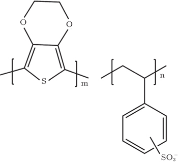
Since polymer light-emitting devices (PLEDs) were invented by Burronghes et al. at Cambridge University in 1990[1] a great deal of effort has been made to improve the performances of PLEDs, such as lifetime and high luminous efficiency in order to meet commercial requirements. A successful approach to improving the performance of PLED was to insert poly(3,4-ethylenedioxythiophene):poly(styrenesulfonate) (PEDOT:PSS) between the anode (indium tin oxide, ITO) and the light-emitting polymer as a hole transport layer.[2] Similarly, PEDOT:PSS with molecular structures shown in Fig. 1 was also used as a hole transport layer to improve the performances of organic solar cells (OSCs).[3–5] An additional acidic PEDOT:PSS buffer layer helps to increase the hole extraction efficiency.[6,7] A dramatic improvement in the lifetime and luminous efficiency has been observed for PLEDs by using this buffer layer, and a large enhancement in short circuit currents have been shown in OSCs.[8,9] However, the introduction of PEDOT:PSS leads to problems relating to the stability of the interface due to its strong acidic nature.[10] When ITO is exposed to air and etched by PEDOT:PSS, indium reaches a saturation concentration in the PEDOT:PSS, 1.2 at.% for several days.[11] Crispin et al. further demonstrated that the In 3d5/2 in PEDOT:PSS is located at 445.2 eV, similar to that of InCl3 at 445.7 eV. This suggests that the indium oxidation state in the PEDOT:PSS is 3+.[12] Indium in PEDOT:PSS is not desirable as it degrades the performance of PLEDs. Wong et al. tried to block indium from leaching out of ITO, by depositing a self-assembled monolayer of alkylsiloxanes on ITO before spin coating PEDOT:PSS.[13] More recently nickel oxide (NiO)[14] and tungsten-oxides (WOx)[15] layers were employed to suppress the indium diffusion from ITO to PEDOT:PSS. They were also able to prevent acidic damage to the ITO and the organic emission layer caused by sulfate ions in PEDOT:PSS. V2O5-doped PEDOT:PSS improved the performances of PLEDs and suppressed the diffusion of indium.[16] In De Kok et al.’s work, PEDOT:PSS layers were modified by NaOH and they demonstrated that PLEDs comprised of Na+-rich, proton poor PEDOT:PSS can show lower lifetime and efficiency than the Na+-free, proton-rich devices. This was attributed to the pH-effect instead of the electrochemical loss of the dopant. NaOH modification of PEDOT:PSS results in the salt PSSNa without changing the oxidation state of PEDOT, i.e., without doping/undoping the materials.[17]
The mechanism of the indium effect on the performance of PLEDs is not fully resolved, especially its effects on a biased PLED. Indium ions and/or electrons in PLED will be moved under the action of an electric field
when biased, the interaction between indium ions and PEDOT:PSS will occur. However, the thickness of PEDOT:PSS film in PLED is about 50 nm, which is not thick enough to disclose the effect of indium ions. Therefore, an electrochromic device with thicker PEDOT:PSS was used to check the effect of indium ions under the action of an electric field. Here in this paper, indium oxide instead of ITO is used as the substrate etched by the PEDOT:PSS due to its integral role in the etching process.[13] For the first time, we have studied the structural changes of modified PEDOT:PSS film by in-situ micro-Raman and laser reflective measurement and also discuss the effects of indium transfer. For comparison, laser reflective measurements of 25-mM LiCl, 25-mM KCl, 25-mM NaCl, or 25-mM InCl3 modified PEDOT:PSS are also presented.
2. Experiment
Indium oxide powder was dissolved with different weight ratios of In2O3 powder (Aldrich product No. 203424) to PEDOT:PSS aqueous solution (Baytron P VP AI 4083 from H.C. Starck) which had been concentrated from 1.3 wt% to 2.76 wt% at 65 °C, and the PEDOT:PSS solution with 0 wt%∼0.3 wt% dissolved In2O3 were successfully prepared. In2O3 powder of more than 0.3 wt% would not be dissolved completely in PEDOT:PSS, and would destroy the stability of PEDOT:PSS. PEG (Aldrich) was first dissolved in DI water and then poured, with the same weight ratio of PEG solid to PEDOT:PSS solid. The relevant PEDOT:PSS films or PEG-PEDOT:PSS films were spin coated on ITO or occasionally on silicon for XPS measurement. The thickness values of films were measured by a surface profiler (Alpha-Step, KLA-Tensor). XPS measurements were performed in an ultrahigh vacuum (UHV) chamber. The UHV system was equipped with a monochromatized Al Kα source and a hemisphere analyzer for XPS. The base pressure of the UHV system was 1.33 × 10⁻⁷ Pa and XPS energy resolution was ∼0.6 eV. The binding energy scale was calibrated against the C 1s line centered at 285.0 eV. In-situ micro-Raman measurements were carried out at room temperature by using a Renishaw Raman System 2000. The 514.5-nm line of argon ion laser was used as the exciting light. The spectra were measured in backscattering geometry. The resolution was about 1 cm−1, a 50 × objective was used to focus the laser light on the sample surface into a spot size of 2 μm.
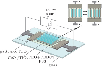
A typical EC device for in-situ micro-Raman measurement is shown in Fig. 2. ITO coated glass was etched to fabricate the finger-type pattern by photolithography. The width values of stripes and channels are each 300 μm. CeO2–TiO2 film, serving as the ion storage layer, was prepared on patterned ITO by the sol–gel method to form a film with a thickness in a range from 150 nm to 250 nm. The relevant PEG-PEDOT:PSS samples were then spin coated on ITO/CeO2–TiO2 with the film thickness values of about 700 nm–900 nm. The device was placed into a vacuum furnace and heated at 80 °C overnight before in-situ micro-Raman measurement.
Fig. 2. Schematic structures of solid state electrochromic devices based on PEG + PEDOT:PSS with and without indium ions fabricated for in-situ micro-Raman measurements.
Another kind of EC device for laser reflective measurement was made from bottom to top as follows: ITO was used as anode, CeO2–TiO2 film as ion storage layer, PEG-PEDOT:PSS with 0.2 wt% dissolved In2O3 (PEG-PEDOT:PSS-In3+) or without indium ions as the EC layer. For comparison, PEG-PEDOT:PSS samples were mixed with either 25-mM LiCl, 25-mM KCl, 25-mM NaCl or 25-mM InCl3 (all metallic halides from Aldrich). Modified PEDOT:PSS was used as an EC layer while silver served as the cathode. In the device fabrication, the ion storage layer was spin coated to form a film with the thickness in a range from 150 nm to 250 nm on ITO. The EC layer with the thickness in a range from 700 nm to 900 nm was then spin coated on ITO/CeO2–TiO2 and then baked in a vacuum furnace at 80 °C overnight. A silver film was thermally deposited in a vacuum on the top of the EC layer to serve as a counter electrode. The device was covered by a glass plate and sealed with epoxy before removing from the dry box for laser reflective measurement. The bias is defined to be positive if the ITO terminal is connected to the anode. The electrochromic properties were characterized by measuring the reflectivity of light from a red HeNe laser at a 90° deflection angle.
3. Results and discussion
PEDOT:PSS is used as a hole injecting material for the PLED when partially oxidized. It is well established that PEDOT has electrochromic characteristics, for it is transparent when doped and dark blue when undoped. As for PLED, PEDOT is at its oxidation state and displays high conductivity and transparency. The performance of PLED degrades if PEDOT:PSS is reduced when voltage is applied.[18,19] For this reason, it is very necessary to investigate the interaction of indium ion with PEDOT:PSS via an electrochemical method. In order to improve the effect of electrochemistry, PEG is added to help ion transfer.
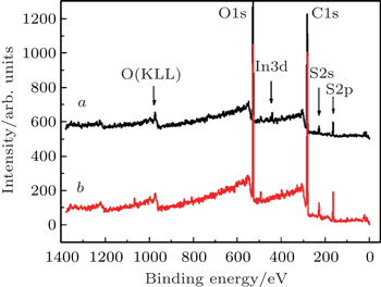
Fig. 3. XPS survey spectra of (curve a) PEG + PEDOT:PSS with indium ions and (curve b) PEG + PEDOT:PSS without indium ions.
Figure 3 (curves a and b) shows the XPS spectra of PEG plus PEDOT:PSS with and without indium ions, marked as PEG-PEDOT:PSS-In3+ and PEG-PEDOT:PSS, respectively. Table 1 lists In/S and Na/S atomic ratios of the above two samples, measured using XPS. For comparison, the corresponding samples without PEG are also provided. It can be seen that the sodium present in PEDOT:PSS originates from the oxidizing agent Na2S2O8 during synthesis.[17] In general, the concentration of sodium in the commercial PEDOT:PSS product is about 400 ppm. Indium oxide dissolved in PEDOT:PSS (0.2 wt%) does not change its Na/S atomic ratio while the In/S ratio increases to 0.1. The introduction of PEG does not significantly change the In/S ratio nor the Na/S ratio. This indicates that the mixture of PEG and PEDOT:PSS were not phase separated into phases.
Table 1.
Table 1.
Table 1.
XPS analyses of PEDOT:PSS, PEDOT:PSS plus PEG and their interactions with indium ions.
.
In/S atomic ratio
Na/S atomic ratio
PEDOT:PSS
–
0.24
PEDOT:PSS + In3+
0.11
0.24
PEDOT:PSS + PEG
–
0.22
PEDOT:PSS + PEG + In3+
0.11
0.19
Table 1.
XPS analyses of PEDOT:PSS, PEDOT:PSS plus PEG and their interactions with indium ions.
.
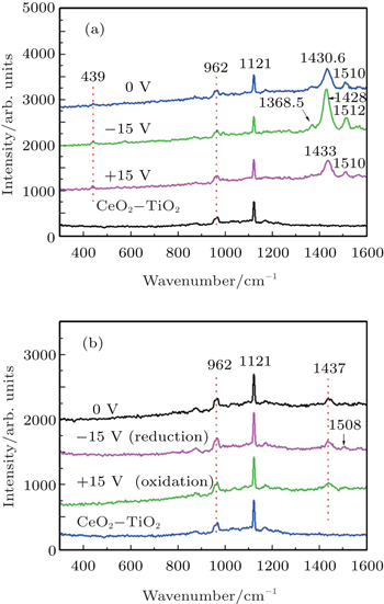
The solid state electrochromic devices based on PEG-PEDOT:PSS-In3+ and PEG-PEDOT:PSS are measured by an in-situ micro-Raman device. The device structure is shown in Fig. 2. The 2-μm-diameter laser spot is projected near the stripes. The in-situ micro-Raman spectra of PEG-PEDOT:PSS-In3+ and PEG-PEDOT:PSS are shown in Figs. 4(a) and 4(b), respectively. With the exception of the spectra for the glass/CeO2–TiO2 substrates, all the other spectra in Fig. 4 are obtained after the relevant devices have been biased for enough time. This is performed in order to diminish the effect of their memory. The Raman bands located at 962 cm−1 and 1121 cm−1 are assigned to CeO2–TiO2 films (ion storage layers). No bands of ITO glass and PEG are observed. The Raman spectrum of as-prepared PEG-PEDOT:PSS-In3+ film is shown in Fig. 4(a) when the device is biased at 0 V. The Raman spectra of reduced and oxidized films are also shown in Fig. 4(a) when the device is biased separately at −15 V and +15 V. All the bands can be attributed to PEDOT with the exceptions of 1121 cm−1 and 962 cm−1. The strong band located at 1430.6 cm−1 can be assigned to C=C stretch vibrations.[20] The bands located at 1512 cm−1 and 1368.5 cm−1 are attributed to asymmetric C=C stretching and C–C stretching respectively.[21–23] When the device is biased at −15 V, it is in a state of electrochemical reduction, the resulting Raman intensity with the bias have the band attributed to PEDOT increase. This is consistent with a simultaneous appearance of the 514-nm laser excited absorption band.[21] When the device is positively biased into an oxidized state, small red-shift occurs and a decrease in intensity is seen. These changes may be attributed to the shortening in the conjugation length of the neutral parts under further oxidation (doping).[18] From Fig. 4(b), however, it can be seen that the strong bands of the Raman spectrum of as-prepared PEG-PEDOT:PSS located at 1437 cm−1 are red-shifted by approximately 6.4 cm−1 compared with PEG-PEDOT:PSS-In3+. The Raman band change in this case is similar to that of the shifts occurring in electrochemical doping. This is due to the Raman bands that are used to probe the conjugation in PEDOT, shift, broaden and intensity reduction when electrochemical doping has occurred. Therefore, we suggest that the introduction of indium ion into PEG-PEDOT:PSS will be analogous to electrochemical doping of PEDOT. When the device based on PEG-PEDOT:PSS is biased at −15 V and +15 V, separately, Raman shift hardly occurs compared with the scenario of as-prepared PEG-PEDOT:PSS, indicating that neither electrochemical doping nor undoping occurs under these conditions.
Fig. 4.in-situ micro-Raman spectra of solid state electrochromic devices based on (a) PEG + PEDOT:PSS+In3+ and (b) PEG + PEDOT:PSS at different applied voltages.
Compared with Figs. 4(a) and 4(b), it is obvious that indium ions play a more important role in determining the electrochemical properties of PEDOT than sodium ions do. This importance occurs in spite of the fact that the atomic concentration of indium is about half of that of sodium ions. It is possible that the performance of PLED hinges much more on indium ions rather than sodium ions in PEDOT:PSS.
To further study the effects of indium ions and sodium ions on the properties of PEDOT:PSS laser, the reflective measurements are conducted on solid state electrochromic devices based on PEG-PEDOT:PSS-In3+ and PEG-PEDOT:PSS. The device structures are ITO/PEG-PEDOT:PSS-In3+/Ag and ITO/PEG-PEDOT:PSS/Ag. Similar characterizations of electrochromic devices were reported in previous work.[24] The electrochromism contrasts of the devices each as a function of negatively biased voltage is shown in Fig. 5. The contrast is defined as (I0–I)/I0, where I0 and I are the reflected light intensity at zero bias and that at the applied voltage, respectively. As seen in Fig. 5, the contrast of the device based on PEG-PEDOT:PSS-In3+ increases from 0 to 0.44 as the applied voltage changes from 0 V to −22 V. On the contrary, the contrast of the device based on PEG-PEDOT:PSS only increases by approximately 0.03. Therefore, the contribution of the sodium ions is negligible compared with the indium ion effect on the reduction of the PEDOT:PSS.
Fig. 5. Variations of electrochromism contrast with applied voltage, measured at 632.8 nm, for devices with structure ITO/PEG+PEDOT:PSS+In3+/Ag (open circle) and ITO/PEG + PEDOT:PSS/Ag (square).
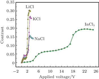
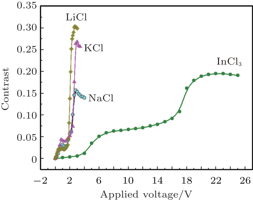
It is also important to investigate the effect of the higher concentration of metallic ions on the electrochromism of PEDOT:PSS. Metallic halides such as LiCl, KCl, NaCl or InCl3 are directly dissolved in PEG-PEDOT:PSS and then electrochromic layers and devices are fabricated. The contrast dependences of applied voltage for the devices based on various metallic halide salts (25-mM LiCl, 25-mM KCl, 25-mM NaCl, 25-mM InCl3 in PEG-PEDOT:PSS solution) are shown in Fig. 6.
It can be seen from Fig. 6 that the redox voltages for the device including Li+, K+, and Na+ are 2.0 V, 2.6 V, and 2.4 V, respectively. The contrasts for the above devices are about 30%, 27%, and 15%, respectively. The results could be attributed to the effect of salts on aqueous solution properties of PEG-PEDOT:PSS.[25] The redox voltages for the devices based on InCl3 salt are more complicated than those based on various alkali halide salts in Fig. 6 and include a plane and two peaks. This is most likely ascribed to the multivalency of indium ions. The contrasts for the devices based on InCl3 increase up to 18%. The ion concentration plays an important role in electrochromsim. In the case of the indium ion effect, the contrasts of electrochromic devices based on PEG-PEDOT:PSS increase from 0.03 to 0.44 with indium concentration increasing from 0 mM to 7 mM. This drops down to 0.18 at a higher indium concentration (25 mM) however, prescribing an optimal value for the concentration needed in electrochromic devices.
Fig. 6. Curves of electrochromism contrast versus applied voltage, measured at 632.8 nm, for devices with structure ITO/PEG + PEDOT:PSS + salt/Ag, salt refers to LiCl (square), KCl (triangle), NaCl (open circle), and InCl3 (circle), separately.
4. Conclusions
In this work, PEG-PEDOT:PSS with and without indium ions are prepared in a homogeneous phase. Two kinds of solid state electrochromic devices based on PEG-PEDOT:PSS-In3+ and PEG-PEDOT:PSS are prepared for in-situ micro-Raman and laser reflective measurements. For comparison, laser reflective measurements of LiCl, KCl, NaCl, InCl3 modified PEDOT:PSS are also presented. The results show that the dopant in PEDOT:PSS may be removed when indium ions are introduced. Indium ions have a stronger influence on the structural properties of PEDOT than sodium ions. Indium ions make PEDOT:PSS remove more sodium ions when the device is negatively biased. The laser reflective measurement shows that the contrast of the device based on PEG-PEDOT:PSS-In3+ is 44%. Comparatively, the contrast of the device based on PEG-PEDOT:PSS is only about 3%. The laser reflective measurement also shows that the contrast of the device fluctuates as a function of the metal salt used.


 , Guo Zheng-Fei1, Qu Jing-Yu1, Pan Kun1, Qi Zheng1, Hong Li2]