

Universal quantum computation using all-optical hybrid encoding*
[Guo Qia), b) , Cheng Liu-Yonga) , Wang Hong-Fub) , Zhang Shoua), b)†  ]
]
]
|
|


†Corresponding author. E-mail: szhang@ybu.edu.cn
*Project supported by the National Natural Science Foundation of China (Grant Nos. 61465013, 11465020, and 11264042).
By employing displacement operations, single-photon subtractions, and weak cross-Kerr nonlinearity, we propose an alternative way of implementing several universal quantum logical gates for all-optical hybrid qubits encoded in both single-photon polarization state and coherent state. Since these schemes can be straightforwardly implemented only using local operations without teleportation procedure, therefore, less physical resources and simpler operations are required than the existing schemes. With the help of displacement operations, a large phase shift of the coherent state can be obtained via currently available tiny cross-Kerr nonlinearity. Thus, all of these schemes are nearly deterministic and feasible under current technology conditions, which makes them suitable for large-scale quantum computing.
Quantum computation has been attracting more and more researchers' attention due to the incredible computational power over its classical counterpart.[1] The qubit is the basic unit of quantum computation, which can be encoded in any two orthogonal pure states, [2] such as, the ground state and excited state of a single two-level system, the two linearly polarized states of a photon, and so on. Therefore, many quantum computation schemes have been proposed in different quantum systems, such as cavity QED, [3, 4] trapped ions systems, [5, 6] quantum dot systems, [7– 9] superconducting quantum systems, [10, 11] and linear optical systems.[12, 13] Among these systems, the linear optical system has always been a research hot spot, because of the robustness and the long decoherence time of photons.
In linear optical quantum computing (LOQC), the qubit is usually encoded in the vertical and horizontal polarization states of the linearly polarized photon, and the quantum logical operations can be achieved by using linear optical elements. However, because of the difficulty of photonic interaction and the probabilistic nature of linear optical quantum gates, it is difficult to achieve deterministic optical quantum information processing.[12] In recent years, cross-Kerr nonlinearity, [14, 15] which is used to introduce the interaction between photons, has been used to achieve some deterministic optical quantum information processing tasks, such as quantum communication, [16– 20] quantum logical operations, [21– 25] and so on. While in practice these schemes may be almost unfeasible, since currently available nonlinearities are extremely weak, even though they are theoretically reasonable.
Besides the polarization encoding scheme, another optical quantum computation strategy is that the qubit is encoded in the two coherent states, denoted as | α 〉 and | – α 〉 , with amplitudes ± α , which is generally called coherent-state quantum computing (CSQC).[26– 31] For large amplitudes, the two states | α 〉 and | – α 〉 can be considered to be approximately orthogonal to each other; however, precisely speaking, because of the nonorthogonality between states | α 〉 and | – α 〉 , single-qubit Z rotations are highly nontrivial and cause a heavy increase of the circuit complexity, [28, 32] which certainly will reduce the success probability of quantum communication and quantum computation. It is easy to define an exactly orthogonal qubit basis by using the symmetric and antisymmetric superposition of the coherent states (| α 〉 ± | – α 〉 ).[27, 33] The major difficulty in this encoding scheme is that the logical qubits are sensitive to the photon loss. That is because the two states (| α 〉 ± | – α 〉 ) correspond to the even/odd photon number parity states, respectively, which means the qubit will bit-flip error as long as one photon is lost. Despite all this, Ralph and Pryde pointed out that parity-based LOQC and CSQC are the best ones among many optical schemes when both the loss threshold for fault-tolerant quantum computing and the resource requirements are considered.[34]
Considering the above facts, Lee and Jeong devised a hybrid encoding scheme very recently to combine the advantages of LOQC and CSQC.[35] They encoded the qubit in the combination of single-photon polarization states and coherent states, i.e., {| 0L〉 ≡ | + 〉 | α 〉 , | 1L〉 ≡ | – 〉 | – α 〉 }, where | ± 〉 = (| H〉 ± | V〉 ) and | ± α 〉 is coherent states with amplitudes ± α . This is a novel encoding strategy and the authors demonstrated that the approach outperforms LOQC and CSQC. However, their universal gate operations were implemented through teleportation protocols.[36] The complicated Bell state measurements for both single photons and coherent states are required for the teleportation protocol. Moreover, different gates require different entangled states as a quantum channel for teleportation, which means one must generate appropriate entangled states as off-line resources before performing a quantum gate. All of this indicate that the teleportation-based quantum logical gates will greatly increase the circuit complexity for large-scale quantum computation. Therefore, it is necessary and also significant to explore a method to implement universal quantum gates directly without the teleportation protocol.
In this paper, we propose an alternative approach to directly implement the universal quantum logical gates of the hybrid qubits with the help of displacement operations and single-photon subtractions. Because there is no teleportation procedure in the present Hadamard gate and controlled-NOT gate, the implementation devices are simpler than the ones in Ref. [35]. Moreover, the present Bell-state analyzer is nondestructive, and can be used for many quantum information tasks. The major components in the present schemes are displacement operations and single-photon subtractions, which can assist arbitrarily weak cross-Kerr nonlinearity to deliver the required nonlinear effect. Other components needed in this paper are the most common linear optical elements, especially, all the required photon detectors are the ordinary detector for distinguishing the presence or absent of photons without resolving the photon's number. We show that all the schemes can be implemented in a nearly deterministic manner.
It is well known that single-qubit gates and controlled-NOT gates together are universal for quantum computation. As discussed in Ref. [35], the Pauli operations can be easily achieved using polarization rotators and phase shifters, which reflects that the hybrid encoding scheme combines the advantages and overcomes particularly weak points of both LOQC and CSQC. For example, the single-qubit phase gate is very complex in the coherent-state encoding scheme, [28] but it can be simply performed by phase operation only on the single-photon mode and no operations on the coherent-state mode in the hybrid encoding system. Another important single-qubit gate is the Hadamard gate, which was implemented via the teleportation protocol in Ref. [35]. Here, we show a method for directly implementing the Hadamard gate.
Take an arbitrarily single qubit in hybrid basis for example to explain the principle of the Hadamard gate,

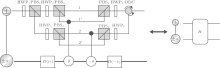
where a and b satisfy | a| 2 + | b| 2 = 1 and a, b ≠ 0.[37, 38] This arbitrarily single qubit is actually an entangled state of a single photon and coherent state, which can be prepared by cross-Kerr nonlinearity as indicated in Refs. [35] and [39]. Figure 1 gives the schematic diagram of the hybrid-qubit Hadamard transformation, in which all the half-wave plates (HWP) are oriented at 22.5° and used to perform the transformations {| H 〉 ↔ | + 〉 , | V〉 ↔ | – 〉 }. The single photon is firstly rotated by HWP1 and split to two spatial modes 1 and 2 by a polarization beam splitter (PBS). The state becomes

here the subscript 1 (2) indicates the spatial mode. Then the single photon is rotated by HWPs again, and the coherent state of the input qubit undergoes a displacement operation D(iγ ), which can be performed by mixing the signal beam with an auxiliarystrong coherent field on a highly unbalanced beam splitter.[40] That is

After that, the two single photon paths are split by PBSs again, and the coherent state will interact with the specified polarized single-photon state through the cross-Kerr nonlinear medium, whose interaction Hamiltonian is 


'> | Fig. 1. Schematic diagram of the hybrid-qubit Hadamard transformation. D(± iγ ) represents the displacement operation, and θ stands for the weak cross-Kerr medium. PBS: polarization beam splitter. HWP: half-wave plate oriented at 22.5° . 1 (1') and 2 (2') indicate different spatial modes of the single photon. ODC: optical directional coupler, which is used to combine spatial modes 1 and 2 to one mode. The diagram at the right represents the circuit shown at the left. |
Then PBS4(5) combine the spatial modes 1(2) and 1′ (2′ ). After rotating the single photon through HWP4(5) and performing an inverse displacement operation D(-iγ ) on the coherent state, the input state will evolve as follows:

Finally, we need to combine the single-photon spatial mode 1 and mode 2 to one spatial mode without changing the polarization of the single photon, which can be easily implemented by common optical prisms or conventional optical directional coupler (ODC) in modern optical communication.[41] Now, the system state becomes

In order to implement the Hadamard transformation, the displacement parameter γ should satisfy
Through a simple calculation, we can obtain γ = α cot(θ /2), and the Hadamard transformation is implemented, i.e.

It is obvious that the Hadamard transformation can be implemented successfully by choosing appropriate γ according to the available phase shift θ . Note that the combining of the spatial modes 1 and 2 in the final step is actually a quantum erasure process of the path information, so the possible error introduced by the quantum erasure will affect the implementation of the scheme. In order to reduce the error, it is required that the wave packets in the two modes arrive at the ODC simultaneously, which can be achieved by accurately matching the length of the two optical paths.
Before introducing the controlled-NOT gate, we firstly review the single photon subtraction. For the coherent state is the eigenstate of the annihilation operator â , i.e., â | ± α 〉 = ± α | ± α 〉 , subtracting a single photon from a large coherent state cannot change the state besides a phase shift. In practice, the photon subtraction can be implemented by a highly unbalanced beam splitter (BSu) with large reflectivity and small transmissivity.[42– 48] Here, the photon detector is used to detect the photon on the transmission beam.
Using single photon subtractions and the present Hadamard gate, we can construct a two-qubit controlled-NOT gate as shown in Fig. 2. An arbitrarily two-qubit in hybrid basis can be written as
where cij (i, j = 0, 1) are normalization coefficients. In the present scheme, only a coherent superposition state 𝒩 + (| α 〉 + | – α 〉 ) is required as auxiliary resource, which can be obtained experimentally.[42] The action of the balanced beam splitter (BSb) is that 


where the subscripts c, t, and a indicate the control qubit, target qubit, and auxiliary, respectively. Now we explain the procedure of the controlled-NOT gate. Firstly, let the coherent state of the control qubit and the auxiliary coherent beam interfere on BSb1. The action of BSb1 can be expressed as the transformations
So the joint state will become

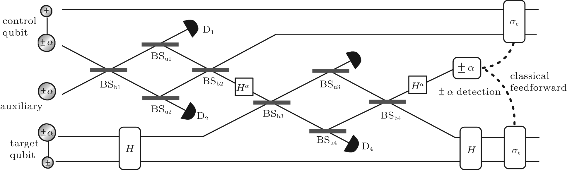 | Fig. 2. Schematic diagram of the two-qubit controlled-NOT gate.BSb represents a balanced beam splitter and BSu is a highly unbalanced beam splitter used to achieve single-photon subtractions. D stands for the ordinary photon detector for distinguishing the presence or absence of photons without resolving the photon’ s number. Hα represents the transformation | ± α 〉 → 𝒩 ± (| α 〉 ± | – α 〉 ). σ c(t) stands for the Pauli rotation on control (target) qubit dependent on the feedforward result of the auxiliary’ s ± α measurement. |
Next, the coherent lights in control and auxiliary qubits undergo the first photon subtraction. Obviously, the components in Eq. (9) that contain the term 


For expressing simply, we neglect the nonsignificant global coefficients in the above formula. Then the two modes pass through BSb2, and the state will become

Then perform a Hadamard transformation on the target qubit using the device proposed in the above subsection. The auxiliary qubit also undergoes the Hα operation, followed by the second subtraction. Similar to the process from Eq. (8) to Eq. (12), let the coherent state of the control qubit and the auxiliary coherent beam pass through BSb3, BSu3(4), and BSb4 successively. During the process, if the detector D3 clicks, the state is given by

Next, the auxiliary and the target qubits undergo Hα operation and Hadamard transformation, respectively, and the state reads

Finally, perform a projection detection on auxiliary qubits under the basis {| α 〉 , | – α 〉 }. If the detection result is | α 〉 , we should respectively perform the Pauli Z operation σ z and Pauli X operation σ x on the control qubit and target qubit, i.e., σ c = σ z and σ t = σ x. Otherwise, if the detection result is | – α 〉 , σ c = σ z and σ t = I, that is, no operation is required for the target qubit. Then the controlled-NOT gate is achieved. Note that the controlled-NOT gate can only be successfully realized for the cases that two detectors click (one is from D1 and D2, the other is from D3 and D4). All the successful detection outcomes and the corresponding single-qubit Pauli rotations are listed in Table 1.
| Table 1. The detection outcomes and the corresponding feedfoward operations. σ c (σ t) indicates the operation performed on the control (target) qubit. I is the identity matrix and σ x (σ t) is the Pauli X (Z) operator. |
We assume that all the beam splitters work in the ideal case. Theoretically, the scheme or photon subtractions will be unsuccessful, only when the outputs of balanced beam splitters BSb1 and BSb3 are in the vacuum states. The probability that both the two outputs of each balanced beam splitter are in the vacuum states is 

Bell-state analyzer, i.e., Bell-state measurement, is the basic component of many quantum information processing. The four Bell states in hybrid basis can be written as

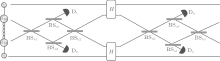
The present Bell-state analyzer is shown in Fig. 3. The two coherent states in the Bell states interfere with each other on the balance beam splitters. The unbalanced beam splitter is used to achieve the single photon subtraction. During the Bell-state analysis process, the state | ϕ + 〉 will evolve as follows:
From the above evolution, it can be seen that detectors D1 and D4 will click for the state | ϕ + 〉 , and after passing through the analyzer, | ϕ + 〉 will become another Bell state | ψ – 〉 . In the same way, other states can be distinguish using the analyzer. For details, D1 and D3 click for | ϕ – 〉 ; D2 and D4 click for | ψ + 〉 ; D2 and D3 click for | ψ – 〉 . In addition, the Bell-state analyzer leaves the states | ϕ – 〉 and | ψ + 〉 invariant and interchanges the states | ϕ + 〉 and | ψ – 〉 , which can get back to the initial states via local operations. It seems that the Bell-state analysis can be deterministically achieved, however, we need to note that the coherent states in the hybrid qubits undergo two photon subtractions during the whole process. As discussed in the above subsection, the failure probability of the photon subtraction after BSb1(b3) is 
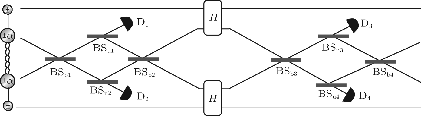 | Fig. 3. Schematic diagram of a complete nondestructive Bell states analyzer. All the elements are the same as those in Fig. 2. |
So far, we have shown the schemes for the single-qubit Hadamard gate, the two-qubit controlled-NOT gate, and the Bell-state analyzer. In principle, these schemes are nearly deterministic. However, considering the actual experimental errors and photon loss, the schemes should be probabilistic. The decoherence effects in a lossy environment can be induced by solving the master equation[35, 49, 50]

where κ is the energy decay rate, and 

and PB = (1 − e− 2| α | 2)2, respectively. In addition, when performing the transformation | ± α 〉 → 𝒩 ± (| α 〉 ± | – α 〉 ) on the auxiliary 𝒩 + (| α 〉 + | – α 〉 ) to implement the controlled-NOT gate, we have let 

For the case that D1 and D3 click, and the detection result of the auxiliary is | α 〉 , after the corresponding local operations, the final state will be

Without loss of generality, assuming that c00 = c01 = c10 = c11 = 1/2, we can obtain the fidelity of the controlled-NOT gate is

which is close to 1 for | α | > 1. We plot the change of PC, PB, and the fidelity of the controlled-NOT gate with the amplitude of the coherent state | α | in Fig. 4, which shows that the probabilities and the fidelity are higher for bigger | α | .
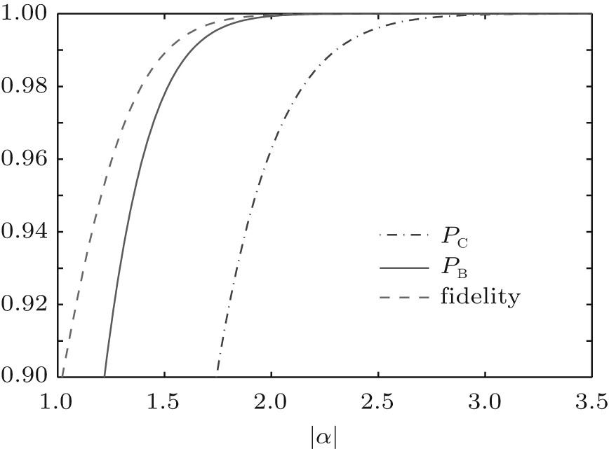 | Fig. 4. The probabilities of controlled-NOT gate PC, Bell state analyzer PB, and the fidelity of the controlled-NOT gate versus the amplitude of the coherent state | α | . |
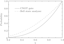
The schemes in the present paper need several photon detectors. Although these detectors here are only required to distinguish the vacuum and nonvacuum states rather than distinguish the number of the photons, the quantum efficiency of the conventional photon detector will affect the performance of the schemes. Assume that all the detectors in these schemes have the same quantum efficiency η that directly determines the success probabilities of these schemes. The present controlled-NOT gate and Bell-state analyzer require three and two detectors click, respectively, so the detector’ s efficiency will respectively decrease their probabilities by η 3 and η 2. We show the effect of η on the success probabilities in Fig. 5, which indicates higher probabilities can be achieved for higher detection efficiency.
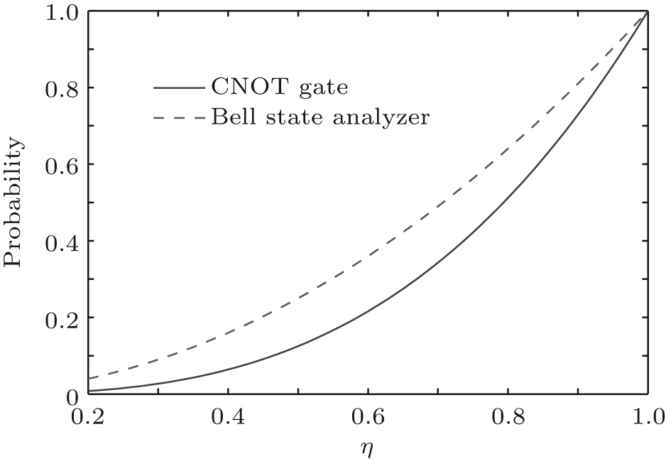 | Fig. 5. The success probabilities of controlled-NOT gate and Bell state analyzer versus the detector’ s quantum efficiency η . |
On the other hand, the photon loss of the coherent state may cause the phase-flip error, which means that coherent superposition state 𝒩 ± (| α 〉 ± | – α 〉 ) is sensitive for odd photons loss. From the above analysis, it can be seen that our schemes are nearly deterministic for large | α | in the ideal conditions. However, considering the imperfections in practical experiments such as the precision of the beam splitters, the quality of the light source, and so on, the implementation of the present schemes must be probabilistic. In Ref. [45], Tipsmark et al. realized the Hadamard gate for a coherent state with low success probability and high fidelity by using photon subtractions, which demonstrates the present schemes are feasible in current achievable conditions at least.
In summary, we have proposed a feasible implementation of universal quantum logical gates for hybrid qubits, which can be implemented in a nearly deterministic manner. Compared with the schemes in Ref. [35], the major advantage of our schemes is that universal quantum gates for hybrid qubits can be directly implemented without the help of the teleportation process, which means the present schemes can greatly decrease the complexity of the universal quantum logical gates and reduce the requirement of the off-line entanglement resources. Moreover, the present Bell-state analyzer can be used to simplify the teleportation of Ref. [35]. Since the schemes can be achieved with the current technology, it may be useful for the large-scale hybrid-qubit quantum computation.
| 1 |
|
| 2 |
|
| 3 |
|
| 4 |
|
| 5 |
|
| 6 |
|
| 7 |
|
| 8 |
|
| 9 |
|
| 10 |
|
| 11 |
|
| 12 |
|
| 13 |
|
| 14 |
|
| 15 |
|
| 16 |
|
| 17 |
|
| 18 |
|
| 19 |
|
| 20 |
|
| 21 |
|
| 22 |
|
| 23 |
|
| 24 |
|
| 25 |
|
| 26 |
|
| 27 |
|
| 28 |
|
| 29 |
|
| 30 |
|
| 31 |
|
| 32 |
|
| 33 |
|
| 34 |
|
| 35 |
|
| 36 |
|
| 37 |
|
| 38 |
|
| 39 |
|
| 40 |
|
| 41 |
|
| 42 |
|
| 43 |
|
| 44 |
|
| 45 |
|
| 46 |
|
| 47 |
|
| 48 |
|
| 49 |
|
| 50 |
|