

Krypton ion irradiation-induced amorphization and nano-crystal formation in pyrochlore Lu2Ti2O7 at room temperature
[Xie Qiu-Rong, Zhang Jian† , Yin Dong-Min, Guo Qi-Xun, Li Ning]
, Yin Dong-Min, Guo Qi-Xun, Li Ning]
|
|


†Corresponding author. E-mail: zhangjian@xmu.edu.cn; jianchng@gmail.com
*Project sponsored by the National Natural Science Foundation of China (Grant No. 11205128) and the Fundamental Research Funds for the Central Universities, China (Grant No. 2012121034).
Polycrystalline pyrochlore Lu2Ti2O7 pellets are irradiated with 600-keV Kr3+ ions up to a fluence of 1.45 × 10¹⁶ Kr3+/cm2. Irradiation induced structural modifications are examined by using grazing incidence x-ray diffraction (GIXRD) and cross-sectional transmission electron microscopy (TEM). The GIXRD reveals that amorphous fraction increases with the increase of fluences up to 2 × 10¹⁵ Kr3+/cm2, and the results are explained with a direct-impact model. However, when the irradiation fluence is higher than 2 × 10¹⁵ Kr3+/cm2, the amorphous fraction reaches a saturation of ∼80%. Further TEM observations imply that nano-crystal is formed with a diameter of ∼10 nm within the irradiation layer at a fluence of 4 × 10¹⁵ Kr3+/cm2. No full amorphization is achieved even at the highest fluence of 1.45 × 10¹⁶ Kr3+/cm2 (∼36 displacement per atom). The high irradiation resistance of pyrochlore Lu2Ti2O7 at higher fluence is explained on the basis of enhanced radiation tolerance of nano-crystal structure.
Pyrochlore A2B2O7, which belongs to space group 
Numerous studies have shown the crystalline-to-amor-phi-za-tion transformation by in-situ ion irradiation.[3, 8– 10] For heavy ion irradiation, the structural damage is generally attributed to the formation of displacement cascades. Also, lots of theories on the mechanism of amorphization have been proposed, such as direct-impact amorphization within an individual collision cascade, the local accumulation of high defect concentration due to the overlap of collision cascade, [11– 13] direct-impact combined with cascades, etc. In this study, grazing incidence x-ray diffraction (GIXRD) and ex-situ TEM are implemented to determine the structure changes induced by heavy ion irradiation.
Polycrystalline pyrochlore Lu2Ti2O7 pellets were prepared by traditional ceramic processing. The Lu2O3 (99.9% pure) and TiO2 (99.99% pure) powders were first heated at 1000 ° C for 10 h to remove moisture and other volatile impurities. Stoichiometric amounts of the reactants were weighed to acquire the composition of Lu2Ti2O7. Firstly, the thoroughly ground mixtures were heated in pellets form at 1300 ° C for 24 h. In order to attain a better homogeneity, the products obtained after first heating were reground, pelletized, and heated at 1450 ° C for 48 h. Then, pellets were cut with a diamond saw and the specimens were polished to a 0.5-μ m diamond finish. These pellets were examined with normal x-ray diffraction, and found to possess pyrochlore structures, and the measured densities of these samples are all found to be 7.038 g/cm3, approximately 96% of their theoretical value (ρ theoretical = 7.328 g/cm3).
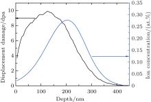
The well-polished samples were irradiated with 600-keV Kr3+ ions at room temperature (RT) in the Ion Beam Materials Laboratory at Los Alamos National Laboratory, using a 200-kV Danfysik High Current Research Ion Implanter. The irradiation fluences range from 5 × 10¹⁴ Kr3+ /cm2 up to 1.45 × 10¹⁶ Kr3+ /cm2. The 600-keV Kr3+ ions were implanted at normal incidence with an average flux of ∼ 1.0 × 10¹² (Kr/cm2)/s. Figure 1 shows the Monte Carlo simulation results of 600-keV Kr3+ ion implanted on Lu2Ti2O7 to a fluence of 4.0 × 10¹⁵ Kr3+ /cm2, obtained by using the stopping and range of ions in matter (SRIM) code.[14] An arbitrary but reasonable threshold displacement energy of 40 eV is used for all atoms in these SRIM calculations.
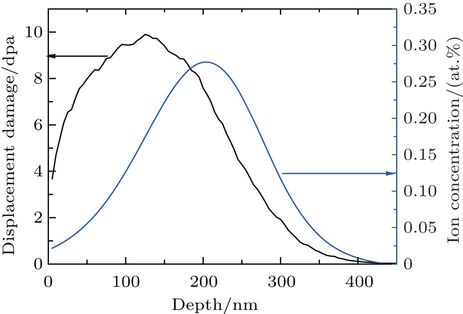 | Fig. 1. SRIM simulation results of displacement damage and implanted Kr3+ ion concentration as a function of depth for 600-keV Kr3+ ion irradiation of Lu2Ti2O7 to a fluence of 4.0 × 10¹⁵ ions/cm2. |
Pristine and irradiated samples were characterized using grazing incidence x-ray diffraction (GIXRD). GIXRD measurements were performed using a Rigaku Ultima IV Advanced x-ray diffractometer, with Cu Kα radiation, α – 2θ geometry, parallel beams. The α – 2θ scans were performed in steps of 0.02° and a dwell time of 2 s. X-ray patterns were recorded at a glancing incidence angle of α = 0.5° to investigate only the irradiation layer. Integrated peak intensities were measured by fitting the diffraction peaks with pseudo-Voigt profiles to estimate the amorphization fraction. To prepare the cross-sectional TEM specimens, the sample irradiated to a fluence of 4 × 10¹⁵ Kr3+ /cm2 was polished to a thickness of below 10 μ m using a diamond lapping film, followed by thinning to electron transparency using 4-keV Ar+ ion milling. TEM observations were conducted using an FEI Tecnai F30 instrument operating with an accelerating voltage of 300 kV. Selected area electron diffraction (SAED) was used in this study to obtain electron diffraction patterns from small sample regions (diameter of ∼ 150 nm).
Figure 2 gives the GIXRD patterns obtained from the Lu2Ti2O7 irradiated with 600-keV Kr3+ ions to a fluence of 1.45 × 10¹⁶ Kr3+ /cm2, with the x-ray incidence angle α varying from 0.1° to 3.0° . It is observed that the amorphous fraction increases with the incidence angle α increasing from 0.1° to 0.5° . Then the amorphous fraction decreases with the penetration depth of x-ray increasing, which covers more and more substrate layer at higher α . Therefore, the x-ray incidence angle is fixed at α = 0.5° in the following GIXRD measurements, which is reasonable and the penetration depth of x-ray at α = 0.5° is within the irradiation layer.
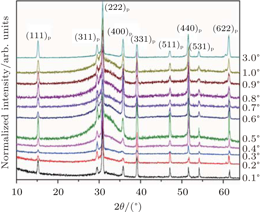 | Fig. 2. GIXRD patterns obtained from the Lu2Ti2O7 irradiated with 600-keV Kr3+ ions to a fluence of 1.45 × 10¹⁶ ions/cm2 at room temperature, with the x-ray incident angle (α ) varying from 0.1° to 3.0° . |
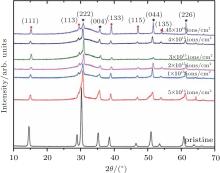
Figure 3 shows the GIXRD patterns obtained from pristine Lu2Ti2O7 and Lu2Ti2O7 irradiated to a fluence up to 1.45 × 10¹⁶ Kr3+ /cm2. The diffraction patterns are offset for clarity. As a superstructure of fluorite, pyrochlore produces a diffraction pattern containing two subsets of intensity maxima. The first subset pattern contains only the diffraction from the fluorite subcell. Especially the diffraction pattern containing the information regarding the fluorite subcell must comply with the conditions where h+ k, k+ l, l+ h must be a multiple of four (hkl: h+ k = 4n, k+ l = 4n, l+ h = 4n).[15] The details of these starred diffraction peaks are shown in Fig. 3. The second subcell with lower intensity is marked with a solid circle, corresponding to the supercell of the ordered pyrochlore structure, contains all of the information about the perturbations required for the formation of an ordered pyrochlore structure from an ideal fluorite arrangement. The intensities of these diffraction maxima are strongly correlated with (i) the difference between the scattering powers of the cations that occupy A- and B-sites, (ii) the occupancies of cation and anion sites, (iii) the displacement of 48f oxygen from the ideal fluorite structure, and (iv) the temperature-factor coefficient.[16] Also it needs to be noted that the scattering power of oxygen is relatively small compared with that of cations in x-ray diffraction, so that the influence of cations is predominant for XRD patterns. For cations at the A-site and B-site, extra conditions of superstructure reflection are allowed for hkl: h = 2n + 1 or h, k, l = 4n + 2 or h, k, l = 4n.[15]
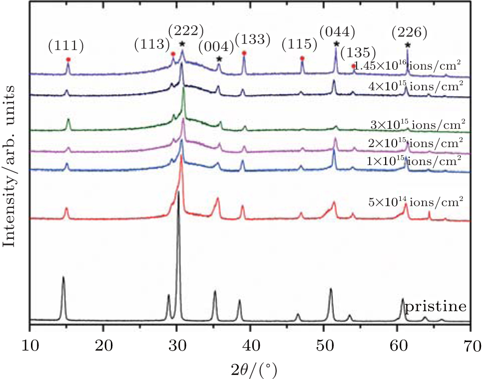 | Fig. 3. GIXRD patterns of pristine pyrochlore Lu2Ti2O7 and Lu2Ti2O7 irradiated by 600-keV Kr3+ ions with fluencies ranging from 5 × 10¹⁴ ions/cm2 to 1.45 × 10¹⁶ ions/cm2. |
In Fig. 3, the GIXRD patterns also display the evolutions of amorphous fraction with irradiation fluence with 600 keV Kr3+ from 5.0 × 10¹⁴ Kr3+ /cm2 to 1.45 × 10¹⁶ Kr3+ /cm2 in Lu2Ti2O7. This amorphization transformation is accompanied by the pronounced broadening of the main diffraction peaks between 25° and 35° of 2θ . Concomitantly, the Bragg maxima decrease with the increasing of fluence. The GIXRD patterns reveal that the amorphous fraction significantly increases with increasing ion fluence to 2.0 × 10¹⁵ Kr3+ /cm2, however, with continuously increasing the irradiation fluence up to 1.45 × 10¹⁶ Kr3+ /cm2, the amorphous fraction almost remains unchanged. It is interesting that all sharp diffraction maxima stay at the maximum fluence (∼ 36 dpa), which is indicative of crystalline pyrochlore, in other words, complete amorphization is not observed in our GIXRD patterns, even though at the maximum fluence.
A quantitative analysis of the amorphous fraction is completed by calculating the intensity ratios of pyrochlore primary (222) diffractions from different irradiation fluences to the pristine sample to obtain the crystallinity, and the results are shown in Fig. 4.
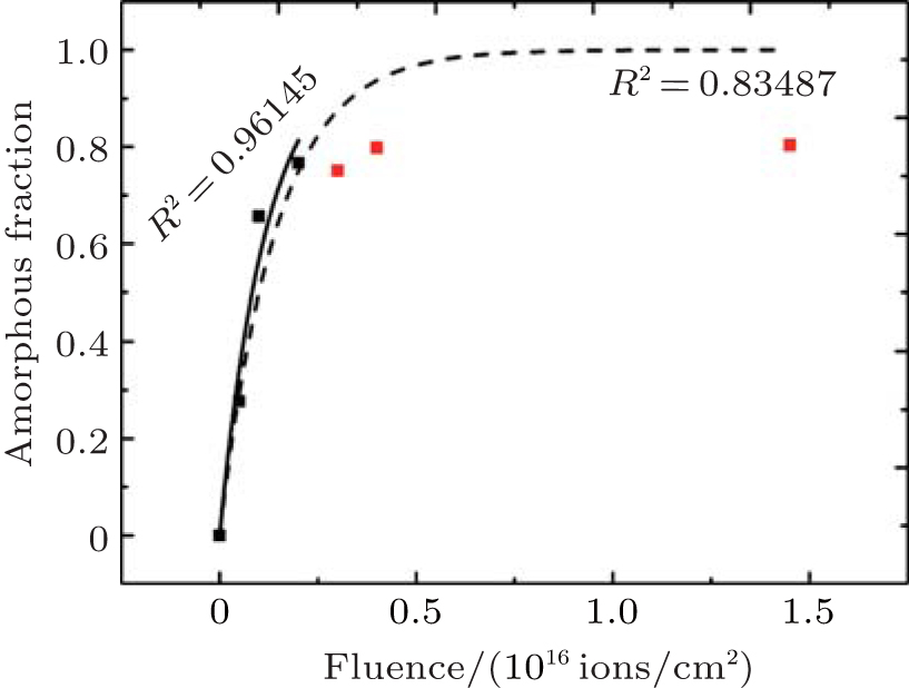 | Fig. 4. Amorphous fraction determined from quantitative analysis of XRD patterns as a function of frequency. The results are fitted using a direct impact model, the dash line represents full fitting; the solid line only fits the low fluence results. |
Specifically, the GIXRD measurements are fitting background with medium cubic-spline, and integrated diffraction peak intensities of pyrochlore and amorphization phases are measured by fitting the diffraction patterns with pseudo-Voigt profiles. Then, the one minus crystallinity will be the fraction of amorphous. The amorphous fraction is observed to gradually evolve into a plateau with increasing irradiation fluence to 2.0 × 10¹⁵ Kr3+ /cm2, and then the amorphous faction reaches saturation at higher fluence. Actually, the amorphization may occur when the accumulation of defects created by ion irradiation exceeds the critical concentration necessary for amorphization. Furthermore, direct impact amorphization is considered to be one of the fundamental amorphization mechanisms for complex ceramics under heavy-ion irradiation. Based on the direct-impact model, a highly energetic incident ion transfers its kinetic energy to the target within 10− 13 s, and creates a displacement cascade, typically a few nanometers in size. The highly energetic zone quenches quickly (within a few ps) to form a small amorphous domain. Later on, epitaxial recrystallization may occur at the boundary of the amorphous phase and crystalline phase, and with increasing irradiation dose, the residual crystalline size turns smaller and smaller. Based on the analyzed amorphous fraction in Fig. 4, the damage evolution of lower fluence (less than 2 × 10¹⁵ Kr3+ /cm2) can be well described by a direct-impact model with the following form[17]

where fa represents the amorphous fraction at a given fluence (Φ ), and σ is the cross-sectional area of the cascade produced by each individual ion. However, at high fluence, this direct-impact model does not match the experiment results any more, and complete amorphization cannot be achieved due to the fact that the irradiation induces the nano-crystal to enhance the radiation tolerance and the low critical amorphization temperature Tc = 450 K of Lu2Ti2O7.[3]
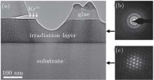
In order to better understand the enhanced radiation tolerance of pyrochlore Lu2Ti2O7 at higher fluences, the sample irradiated to a fluence of 4 × 10¹⁵ Kr3+ /cm2 is cut for cross-sectional TEM observation.
Figure 5 shows cross-sectional TEM bright-field micrographs with corresponding selected area electron diffraction (SAED) patterns. Figure 5(a) displays two kinds of distinctive diffraction contrasts due to the 600-keV Kr irradiation damage in pyrochlore Lu2Ti2O7, and the thickness of the surface damage layer is ∼ 140 nm, in a reasonable agreement with the SRIM calculation shown in Fig. 1. Furthermore, SAED implies that nano-size crystals are formed in the damaged layer in Fig. 5(b), while figure 5(c) indicates that the substrate layer is still single crystal, which demonstrates that the nano-crystals in the damaged layer are induced by ion irradiation.
 | Fig. 5. (a) Cross-sectional TEM micrograph and (b) and (c) corresponding SAED diffraction patterns of Lu2Ti2O7 samples subjected to 600-keV Kr3+ ion irradiation to a fluence of 4 × 10¹⁵ ions/cm2 at room temperature. Panel (b) comes from irradiated layer, and panel (c) from substrate. |
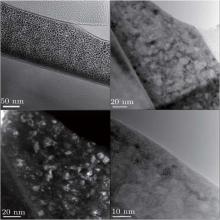
Figure 6 shows the high magnification TEM images of the surface damage layer, where the nano-crystals with a diameter of about 10 nm are observed and have similar orientations, which implies that the epitaxial recrystallization dominates the formation of nano-crystals. According to the study on the mechanism of nano-crystal formation, [18– 20] the ion irradiation induced nano-crystallization formation occurs near the critical amorphization temperature Tc, which is a result of the competition between the formation of amorphous domains and recovery by recrystallization. Furthermore, in the case of pyrochlore Lu2Ti2O7, the irradiation-induced nano-crystals possess the pyrochlore structure on the basis of the GIXRD pattern. In this high magnification TEM study, the sample is irradiated to a fluence of 4 × 10¹⁵ Kr3+ /cm2, the peak dpa is ∼ 10 dpa, which is significantly larger than the normal critical amorphization dose ∼ 1 dpa.[15]
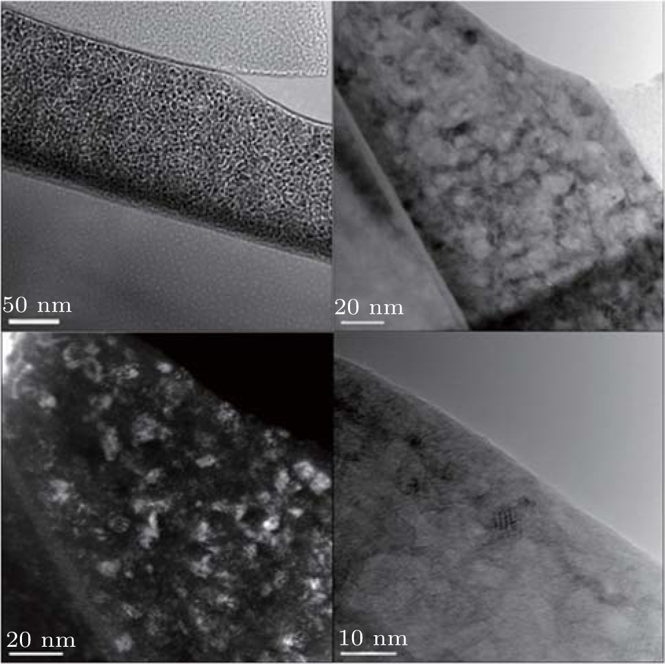 | Fig. 6. High magnification TEM images of pyrochlore irradiated by 600-keV Kr3+ at room temperature to a fluence of 4 × 10¹⁵ ions/cm2, showing the formation of nano-crystal pyrochlore in an amorphization matrix. |
On the basis of GIXRD and cross-sectional TEM observations, it is uncovered that the amorphous fraction increases with increasing ion fluence at lower fluence. While the amorphous fraction does not vary any more with fluence varying from 2.0 × 10¹⁵ Kr3+ /cm2 to 1.45 × 10¹⁵ Kr3+ /cm2, and nano-crystals with an average diameter of ∼ 10 nm are observed. In this study, the incomplete amorphization at higher fluences seems to be due to the formation of nano-crystals which improve the irradiation tolerance of pyrochlore. The enhanced radiation tolerance in nano-crystalline material has been demonstrated in many ceramic materials.[21, 22] As is well known, the microscopic effect of the ion irradiation in a solid is to create point defects (i.e., vacancy-interstitial Frenkel pairs) by dislodging atoms from normal lattice sites. The subsequent behavior of irradiation-produced point defects exerts a great, usually detrimental, influence on the macroscopic structure and properties of the irradiated material (i.e. swelling and amorphization). One means to suppress accumulation of point defects is to annihilate freely-migrating point defects (interstitials and vacancies) at defect sinks, such as free surfaces (e.g., solid-vapor interfaces) and solid-solid interfaces (e.g., grain boundaries, twin boundaries and inner-phase interfaces). Therefore, once the ion irradiation to a fluence of 2 × 10¹⁵ Kr3+ /cm2 in pyrochlore Lu2Ti2O7, smaller nano-crystals are formed, and provide enough defect sinks to annihilate the interstitials and vacancies. Although the irradiation fluence continuously increases, the ion irradiation produced point defects will diffuse to grain boundaries, and ultimately annihilate at grain boundaries. In other words, the point defects are recombined at grain boundary sinks, and the amorphous fraction will not increase even under an irradiation fluence of 1.45 × 10¹⁶ Kr3+ /cm2. That is, the nano-crystalline Lu2Ti2O7 formation enhances its irradiation tolerance to amorphization.
Pyrochlore Lu2Ti2O7 is irradiated at RT with 600-keV Kr3+ to examine its radiation tolerance. The Lu2Ti2O7 pyrochlore is susceptible to amorphization, and the amorphization fraction increases with increasing dose at low fluences, which can be well fitted by using the direct-impact model. However, the amorphous fraction does not change any more due to the formation of nano-crystals at higher fluence. These nano-crystals possess the same composition and structure of pyrochlore Lu2Ti2O7. The pyrochlore amorphous fraction does not increase at higher fluence due to the fact that the nano-crystalline formation enhances its irradiation tolerance.
The authors thank Y. Q. Wang at Ion Beam Materials Laboratory. in LANL for providing the ion irradiation support, and also M. Tang and C. Sun in MST-8 for the fruitful discussion and measurement assistance.
| 1 |
|
| 2 |
|
| 3 |
|
| 4 |
|
| 5 |
|
| 6 |
|
| 7 |
|
| 8 |
|
| 9 |
|
| 10 |
|
| 11 |
|
| 12 |
|
| 13 |
|
| 14 |
|
| 15 |
|
| 16 |
|
| 17 |
|
| 18 |
|
| 19 |
|
| 20 |
|
| 21 |
|
| 22 |
|