Minimizing the effect of noise is essential for quantum computers. The conventional method to protect qubits against noise is through quantum error correction. However, for current quantum hardware in the so-called noisy intermediate-scale quantum (NISQ) era, noise presents in these systems and is too high for error correction to be beneficial. Quantum error mitigation is a set of alternative methods for minimizing errors, including error extrapolation, probabilistic error cancellation, measurement error mitigation, subspace expansion, symmetry verification, virtual distillation, etc. The requirement for these methods is usually less demanding than error correction. Quantum error mitigation is a promising way of reducing errors on NISQ quantum computers. This paper gives a comprehensive introduction to quantum error mitigation. The state-of-art error mitigation methods are covered and formulated in a general form, which provides a basis for comparing, combining and optimizing different methods in future work.
Quantum computers have the potential of outperforming classical computers in solving certain problems.[1] With a particular problem, one needs to map a quantum algorithm into quantum circuits that the quantum hardware can execute. However, the quantum state stored in any physical system, no matter superconducting qubits, trapped ions, etc.,[2] has a limited life time due to interactions with the environment. Besides, any operation is associated with noise. These altogether lead to unreliable computing outcomes. For superconducting qubits, the error rate per two-qubit gate, i.e., the probability of an error occurring in the gate, is about 0.5% with current technology.[3] The error rate limits the number of quantum gates in a circuit, to merely a thousand.[4,5] Therefore, it is necessary to minimize the impact of noise in a quantum circuit, generally by the means of quantum error correction (QEC) or quantum error mitigation (QEM).
QEC is the conventional method to correct errors by taking the use of quantum error correction codes. Quantum states are encoded into some code space, which is a subspace of the entire Hilbert space – physically, a logical qubit is encoded into several physical qubits. The encoding, error detection and correction are realized with quantum gates that are also noise-prone. Therefore, if the physical error rate per gate is higher than a certain threshold, performing error correction can introduce more errors than that it can correct.[6] QEC also requires an overhead cost on qubits for encoding the logical information. For example, when the physical error rate is 10−3, about 1.4 million qubits are required to calculate the electronic structure of 54 spin-orbitals using the surface code.[7] With the current technology, it is still challenging to experimentally demonstrate beneficial error correction in quantum computing.
As the name suggests, QEM methods are designed for mitigating the effect of errors instead of correcting them. They can work in a quantum circuit with an error rate higher than the threshold of QEC, without the large qubit overhead. Therefore, QEM is suitable for quantum devices in the noisy intermediate-scale quantum (NISQ) era,[8] a midway towards fault-tolerant quantum computers[9] in which quantum computing is fully protected by QEC. NISQ devices have only dozens to hundreds of qubits, nevertheless, they have demonstrated the quantum advantage on a specific problem,[4,10] and it is believed that they can retain this advantage to solve practical problems. To achieve this goal, many quantum algorithms[11,12] have been proposed. Incorporating QEM methods is essential for certain applications on NISQ devices.
Various QEM methods have been proposed. In methods such as error extrapolation (or zero-noise extrapolation)[13,14] and probabilistic error cancellation (PEC),[14,15] given some knowledge about the noise, we can compensate errors and make the computing result closer to the true value. These methods do not require additional qubits. The knowledge of the noise, e.g., a parameter such as the error rate or a concrete error model, can be obtained with some characterization methods.[16,17] Alternatively, the parameters used in QEM protocols can be optimized in a learning-based or data-driven manner.[18,19] In symmetry verification[20,21] and virtual distillation,[22–25] errors are eliminated based on certain constrains on the quantum state, i.e., symmetry and purity, respectively. Multiple copies of the noisy state are required for effectively increasing the purity in virtual distillation. These methods are more similar to QEC than error extrapolation and PEC: In a QEC code, a symmetry (i.e., the stabilizer group in stabilizer codes) is constructed at the cost of qubit overhead. In addition to general-purpose QEM methods, protocols are also developed for specific algorithms.[26–28] For example, the quantum subspace expansion[26,27] is a protocol designed to reduce errors in a variational quantum eigensolver.[29]
In this paper, we summarize the state-of-the-art error mitigation methods. Although they work in different ways, we formulate them in a general form. In this way, we explicitly define two characteristic quantities of all QEM protocols, the bias and the variance. With the general form, there is a universal way to combine different protocols and optimize them in the leaning-based manner. In Section 2, we introduce the notations and the general form. QEM methods are specifically described and discussed from Section 3 to Section 7. We introduce the Clifford-circuit learning method in Section 8 and summarize the combined methods in Section 9. A summary is given in Section 10.
Notations
Here we introduce the notations used throughout this paper. We consider a quantum circuit with n qubits and N gates. We always assume that qubits are prepared in |0〉⊗n. When free of errors, the quantum circuit realizes the unitary operator U = UNUN – 1 … U1, where Ui is the error-free operator of the i-th gate. At the end of the quantum circuit, the expected value of an observable O is measured. We use C = (UN, UN – 1, … U1, O) to denote the quantum circuit with a specified observable. The error-free final state and computation result are respectively expressed as and , where [U](⋅) ≡ U ⋅ U†. When subjected to noise, the operations of quantum gates are changed to a series of complete-positive maps , where . Typically we can express , where is the noise operation associated with the i-th gate. The erroneous final state and computation result are respectively expressed as and yC = Tr [OρC].
Generally speaking, provided with the original circuit C, quantum error mitigation performs a set of variant circuits (C1, C2,…) with noisy operations and then obtains the error-mitigated result from a formula F. We use to denote the error-mitigated result. The general form of the error-mitigated result iswhere λ1, λ2, …) are the parameters. The formula F as well as the choice of (C1,C2,…) depend on the error-mitigation method. Different error mitigation methods employ different techniques to determine the parameters in the formula.
We characterize an error mitigation method with two quantities, the bias and the variance. In quantum computing, yC is estimated with the random outputs of the circuit C. We denote the estimator of yC with . Usually, is unbiased, i.e., , and the variance depends on the number of circuit executions. For example, if the observable O = Z is the Pauli operator of a qubit, the measurement outcome of one circuit execution is a random number ±1. According to the empirical mean estimator, is the average value of measurement outcomes, and its variance is , where M is the number of circuit executions. Given , the estimator of is according to the error mitigation formula. Bias and variance of the QEM estimator are respectively and . In some error extrapolation protocols and PEC, the formula is linear in yC, thus if each is unbiased, and the bias of the QEM estimator is ; in general this result on the bias does not hold. Usually, error mitigation can reduce the bias while increasing the variance, in comparison with the raw quantum computing without error mitigation (corresponding to ). The schematic diagram of error-free, erroneous and error mitigated computation results can be found in Fig. 1.
Fig. 1. Schematic diagram of quantum computing with and without QEM. The output of the original circuit is fC on an ideal quantum device and yC on a noisy device. Quantum error mitigation performs computations on a set of variant circuits to predict the error-free result with an increased accuracy. A general cost of quantum error mitigation is the enlarged variance.
Error extrapolation
In error extrapolation, the basic routine is to execute the quantum circuit at various noise levels and then extrapolate to the zero-noise limit. The two essential components are extrapolation formulas and error-boosting methods. Error-boosting methods increase the error rate while preserving the error model. With the computation results at increased error rates, we can predict the error-free result according to the extrapolation formulas.
Polynomial extrapolation
The idea of error extrapolation was introduced in works by Li and benjamin[13] and Temme et al.,[14] in which the polynomial fitting function is considered. It is assumed that the erroneous result can be expressed with the polynomial decompositionwhere ϵ is the total error rate of gates in the circuit. Executing the quantum circuit with l (≤ m + 1) different error rates, we can eliminate the first m-th order effects of noise using an m-order polynomial fitting.
Richardson extrapolation When l = m + 1, we can employ the Richardson extrapolation formula∑j=0mλjϵjk=0,∀k=1,2,…,m.
Truncated Neumann series Recently, Wang et al.[30] proposed error mitigation with truncated Neumann series. In this protocol, a formula resembling that in Eq. (3) is used, but the parameters are determined according to the truncated Neumann series. Let be a linear map from a super-operator , which is a squared matrix in the Pauli transfer matrix representation,[17] to the real field . Under the condition of , which can be satisfied if in some consistent norm, it holds thatwhere , and is the binomial coefficient. The proof of Eq. (5) can be found in Appendix B of Ref. [30]. Suppose , where is the overall noise effect and [U] prepares the error-free state . Replacing with and with in Eq. (5), we haveHere can be realized by repeatedly applying for k times. The bias in Eq. (6) decays exponentially with k when the error rate is small.
Exponential extrapolation
In some cases, the exponential extrapolation proposed by Endo et al.[15] has advantages in accuracy. The simplest exponential extrapolation isgiven two error rates ϵ0 < ϵ1. Giurgica-Tiron et al.[31] summarized the extrapolation formulas and introduced a more general form of poly-exponential extrapolation, in which the logarithm of erroneous result fits to a polynomial function. Cai[32] generalized error extrapolation to the multi-exponential functions where the sum of exponents is the fitting function.
The advantage of exponential extrapolation is analyzed by Endo et al.[15] and Cai.[32] Here we briefly summarize the results. In the circuit model, the number of locations prone to errors equals to the number of gates. With a sufficiently large number of gates, the probability of errors occurring at l locations satisfies the Poisson distribution , where μ is the average number of error-occurred locations. Assuming that the occurred error will move the measured expectation towards zero with a probability of α, the erroneous result isand in the N → ∞ limit it becomes an exponential function fCe−μα. The advantage of exponential extrapolation is numerically demonstrated in Refs. [15,31]. Observations of the fidelity decay in experiments, e.g., the results in Ref. [33], also support this conclusion.
Resource cost
Here we briefly discuss the resource cost of error extrapolation. We take Richardson extrapolation as an example. One may think that we can arbitrarily improve the precision by increasing the extrapolation order m in Eq. (2). This is true only when we can exactly measure the value of yC(ϵ), which is impossible because of the shot noise. In fact, if the extrapolation curve interpolates all the data points, such as that in Richardson extrapolation, the variance is increased by a factor around . Therefore, we should in practice choose a proper extrapolation order m. Krebsbach et al.[34] studied the variance–bias trade-off in Richardson extrapolation and proposed the optimal extrapolation order m, spacing |ϵj – ϵj – 1| for each noise rate given the overall sampling overhead. From the perspective of statistics, the increased variance is referred to the phenomenon of overfitting,[35] which can be suppressed with increased number of data points l (≫ m) and by using fitting methods such as least squares rather than Richardson extrapolation.
Error-boosting methods
The first method takes use of Pauli twirling and random Pauli gate insertion.[13] This method relies on the assumption that quantum errors of the single-qubit gates can be ignored comparing with those of multi-qubit gates. We can effectively increase the error via randomly inserting Pauli gates after each multi-qubit gate. Pauli twirling converts an arbitrary noise channel into Pauli noise:[36]where σi,σj ∈ {σI,σx, σy, σz} are single-qubit Pauli operators and σiσj denotes a tensor product. Pij are positive coefficients satisfying Σi,jPij = 1. To implement the Pauli twirling technique, we randomly insert Pauli gates before and after , resulting in , where σa and σb are uniformly sampled from {σI,σx, σy, σz} and accordingly σd σc = [Ui]σbσa. To boost up the error rate, a further step is to randomly insert Pauli gates after each multi-qubit gate. Recall Eq. (9) and assume a small error rate, randomly inserting each Pauli gate σiσj with a probability of rPi,j can boost the error rate from ϵ to (1 + r)ϵ.
The second method is to insert identity-equivalent gates. The approaches to this end include repeating self-invert gates for odd times,[37,38] gate folding[31] and identity insertion.[39] Typically, this method is based onfor arbitrary unitary operator and non-negative integer r. Gate folding according to the above equation will amplify the error rate by a factor of 1 + 2r if the noise operation commutes with the unitary operator and the error rate is small. To be more detailed, suppose the noise operation on the i-th gate is in the form of , the noise operation on the folded gates is , where r′ = 1 + 2r. Here we have assumed commutes with . In the case that α is small, the error rate is enlarged by a factor of 1 + 2r. Primitively, we should fold every erroneous gate with the same r, such that the error model is unchanged. In that case, we can only amplify the total error rate for 1,3,5,… times. To achieve denser spectrum of error rates, we can choose to fold m out of N gates and the error rate is increased by a factor of 1 + 2rm/N. Be aware of that partially folding a circuit may not only increase the total error rate but also severely change the error model, thus it should be subtle when choosing which gate to be folded. To keep the error model as unchanged as possible, Giurgica-Tiron et al.[31] divided the quantum gates into subsets and chose to fold particular gates in each of the subsets. He et al.[39] used the method of random identity insertion. They set r of each gate as a random variable and sampled circuits according to the distribution of r. Recently, Schultz et al.[40] introduced the method of gate Trotterization. They proposed compiling a gate G into products of several gates according to the formula G = (G1/r)r.
The third method is stretching the Hamiltonian. On realistic quantum hardware, quantum gates are implemented by evolving qubits’ state under a controlled time-dependent Hamiltonian denoted by H(t). The stretched Hamiltonian H(t/r)/r can increase the error rate by a multiplicative factor of r under the assumption that the noise generator is independent of the Hamiltonian and constant in time.[14] In experiments, we can realize the stretched Hamiltonian by reducing the pulse strength that controls the qubits while prolonging the pulse time. An illustrative example is, similar to the Rabi stretch for single-qubit in Ref. [41], a spin initialized in the Z-direction evolving under a X-direction magnetic field H = Bσx(t). The method of stretching the Hamiltonian here is to increase the duration t and reduce the field strength B by the same multiple. A more practical example is given in Ref. [42], where it tunes the cross-resonance pulse on a superconducting quantum processor.
Here we briefly discuss the advantages and disadvantages of these three error-boosting methods. The first method requires accurate understanding of the error model, and the error rate is boosted in a pseudo manner, i.e., the error rate is not actually increased but the collective result of random circuits is equal to the result on an error-increased device. The advantage is that, with the aid of reliable gate benchmarking methods such as gate set tomography,[17] the critical condition that boosting error will not change the error model can be fulfilled. The second method is easy to implement. Comparing with the first one, the second method does not need any definite knowledge about the noise model. However, it is at greater risk that the error model is changed when folding gates. This is not a serious problem when with only simple error models such as depolarizing. In general, it may cause that, quoted from Ref. [5], “arbitrarily deviate from the desired result when only slightly more complicated error models are considered”. Both the first and second methods are in the digital level and friendly to cloud-platform users, while the third method requires direct control of the underlying quantum hardware. Nevertheless, pulse-level control is accessible through some hardware providers.[43,44] As shown in the work of Schultz et al.,[40] the amount of increased noise by different methods depends on the time-correlation. The performance of different methods is similar with white noise, but can be significantly different for time-correlated noise.
Multiple noise parameter extrapolation
Hyper-surface fitting[45] and error mitigation via individual error reduction[46] are proposed by Otten and Gray. Both works considered the linear error mitigation formula with multiple noise parameters.
Hyper-surface fitting In reality, a quantum circuit may be subjected to different noise processes, e.g., relaxation and dephasing, thus is characterized with separate error parameters. Suppose there are m distinct error parameters ϵ(1),ϵ(2),…,ϵ(m), we can generalize Eq. (2) to a hyper-surface:We can use the method of least squares to fit this hyper-surface.[45] For example, if there are two error parameters (ϵ(1),ϵ(2)) = (ϵ,δ), we can truncate Eq. (11) to the second order and solvewhereBy minimizing the difference between the left- and right-hand sides of this equation, the error mitigation formula iswhere and ||⋅|| is the Euclidean norm.
Individual error reduction We may divide a quantum computer into several subsystems, e.g., qubits, and each of them can be considered has an individual error source. We write the noise operation in the Lindblad form , where τ is the gate time and L1,L2,…,Lm are Lindblad operators accounting for errors in each of the m subsystems. The first order approximation of isEven though full fault tolerance is prohibitive on a NISQ device, error correction for individual error source may be attainable. With error correction, suppose that we can have the k-th error component reduced, becomeswhere rk quantifies the removed fraction. We consider the density matrix defined aswhere ρ is the final quantum state prepared by and ρ(k) is the final quantum state prepared by . It follows thatwhere ρef is the error-free state. The proof of Eq. (17) can be found in the supporting material of Ref. [46]. This immediately leads to the error-mitigation formulawhere . Note that the additional qubits used to perform individual error correction may introduce extra errorsand change the error model of the whole circuit.
Probabilistic error cancellation
Probabilistic error cancellation (PEC) was proposed by Temme et al.,[14] which is implemented based on a quasi-probability decomposition. A practical method of constructing the formula using gate set tomography and universal gate set was introduced by Endo et al.[15] The basic idea is that an error-free operation can be expressed as a linear combination of erroneous ones. Suppose that the vector β = (β1, β2, …, βN) specifies a quantum circuit (βi specifies the i-th gate) and there exists a circuit decomposition , the error cancellation formula iswhere .
One method to determine the coefficients λβ is to find the quasi-probability decomposition for every gate. With the gate-wise decompositionwhere λi,βi ∈ R and due to the trace-preserving condition. Terms in the circuit decomposition are , and λβ = ∏iλi,βi. To implement the error cancellation, we need to use the Monte Carlo method. We rewrite Eq. (19) aswhere and . The error-mitigated result can be estimated by sampling circuits according to the probability .
One method to determine the gate-wise decomposition is to find the inverse of the quantum noise. Here we take the inverse of Pauli noise as an example. Suppose that the i-th gate is a single-qubit gate subjected to the Pauli noise where σβi ∈ {σI,σx,σy,σz} and Pi, βi are probabilities, the coefficients of its inverse can be determined by solvingwhere is the 4 × 4 identity matrix. The method to construct is by inserting Pauli gates σβi after each , i.e., .
The inverse of typical error models, such as depolarizing and dephasing, can be decomposed with Pauli basis σβi ∈ {σI,σx,σy,σz}. For a general error model, the decomposition basis is a larger gate set[15] whose elements can be synthesized with Clifford gates and the projection operator .
Resource cost
The sampling overhead of PEC is determined by γ. In comparison with the case without error mitigation, the variance in PEC is increased by a factor of ³2: if we use Monte Carlo estimation according to Eq. (21), we need ³2 times more circuit executions in order to achieve the same variance as in the error-free case. Recall that , the sampling overhead increases exponentially with the number of gates N. Consider γi = 1 + O(ϵ/N) and where ϵ is the total error rate, PEC is efficient when ϵ is small.
The sampling overhead depends on the choice of decomposition basis set. For a general noise channel, we can always decompose its inverse with the universal basis set[15] despite that it may not be optimal, i.e., there may exit other decomposition sets, with which we can achieve lower sampling overhead. One example given by Takagi[47] is the cancellation of the general dephasing noise 14,48,49] Realistic quantum noise is complete-positive and trace-preserving (CPTP). As given in Ref. [49], the inverse of a CPTP map is Hermitian-preserving and trace-preserving (HPTP), and there exists the following decomposition:to:Jℰ=λ1JC1−λ2JC2,JC2≥1,JC2=JC2†,where is the Choi-Jamiolkowski isomorphism of Λ and TrB denotes the partial trace over the subsystem B. Equation (26) comes from trace preservation, equation (27) comes from complete positivity and equation (28) comes from the Hermitian preservation of . The physical implementation of a CPTP map such as can be realized on a quantum computer with at most extra n qubits according to the theorem of Stinespring dilation.[48]
Continuous-time formalism
Sun et al.[50] proposed the stochastic PEC, which extends the formulism of PEC for analogue quantum computation, such that the PEC protocol can be engineered at the pulse level and attain extra resilience against gate dependence and non-local noise effects. Stochastic here means randomly choosing time points to add correction operation instead of checking everywhere. We for now modify our notations to adjust to the continuous time formalism. Other than the total number of gates, we here consider N = T/δt, where δt is a small time interval and T is the time when the final state is prepared. During the i-th time interval, the time evolution on a realistic quantum machine iswhere and U(ti) respectively correspond to and Ui in the discrete-gate formalism. We consider the following decomposition of the inverse on an operator set :where is the identity evolution, pj(ti) are positive probabilities, and has absorbed the sign. The coefficients γi = 1 + O(δt), and p0(ti) = 1 – Σj ≥ 1pj(ti) = 1 – O(δt). In practice, it would be excessively time-consuming if we try to correct at every time step ti. Considering the fact that, with p0 ≲ 1, we do nothing at most time points, i.e., the correction is placed at a small number of time points. Thus, one can alternately investigate the distribution of the time duration between two corrections. The probability of no correction is added until time t iswhere Γ(t′) = Σj ≥ 1pj(ti)/δt = O(1). The probability of placing a correction in the interval (t,t + δt) is Γ(t)d t. Thus the probability density of time duration between two corrections is P(t)Γ(t), which can be sampled using the method of inverse transform sampling.
The overhead in the continuous time formalism is given by Hakoshima et al.[51] Rewriting Eq. (30) in the form ofwhere the sign is absorbed in qj(tj), we haveThe above equation enables us to investigate the role of non-Markovian noise played in the resource cost of PEC. Hakoshima et al.[51] demonstrated that non-Markovianity can reduce the PEC resource cost.
Mitigating measurement error
Since the rate of measurement errors is larger than that of two-qubit gate errors in some systems,[4,10] it is crucial to mitigate measurement errors. The widely discussed method to mitigate measurement errors is post-processing according to the results of quantum detector tomography.[52–54]
We consider a positive-operator valued measurement M = (M1,M2,…,ML). According to the Born’s rule, the error-free probability of yielding Mi is . The probabilities consist the vector . We assume that the measurement error can be modeled as the matrix D which transforms the probabilities to , i.e.,Elements of D are positive and satisfy ΣiDij = 1, ∀ j. D can be determined in experiments via quantum detector tomography. We consider that the error-free result fC of our observable is a function of , i.e.,where G denotes the function. For example, if the observable is the Pauli operator σz on the first qubit, the result is , where M|0〉 (M|1〉) projects the first qubit onto |0〉 (|1〉). Combine Eqs. (34) and (35), the formula to mitigate measurement errors isIn practice, due to the existence of coherent errors, may yield un-physical results such as negative probabilities. In that case, we should replace D−1 in Eq. (36) with D′ determined bysubjected to that are normalized positive probabilities and ||⋅|| is the Euclidean norm.
Without multi-qubit correlations, D can be represented as a tensor product of single-qubit measurement errors, i.e.,where D(i) describes the measurement error on the i-th qubit. When there are correlated errors, we should employ efficient methods featuring these correlations.[55,56]
Virtual distillation
Recently, various virtual distillation (VD) methods were proposed in several works. We categorize these methods into two kinds: the multi-copy approach[22,23] and the state verification approach.[24,25]
Given an erroneous state ρ, the purified state ρM/Tr(ρM) has exponentially reduced errors. Suppose we have the following spectrum decomposition of the erroneous state:where are in descending order and P0 – P1 > 0. VD can exponentially suppress error when |ψ0〉 〈ψ0| = ρef. This is because in the purified statethe probability of |ψ0〉 〈 ψ0| exponentially approaches to 1 as M increases. Using the method proposed in the early works,[57,58] it requires nM + ln (M!) qubits to prepare this purified state. VD refers to those recently proposed methods to directly obtain the purified expectationwithout actually preparing the purified state, and in contrast, VD requires at most nM + 1 qubits.
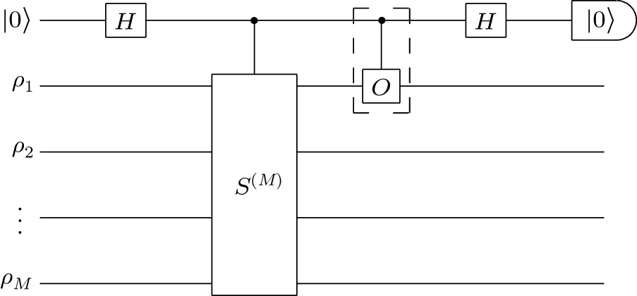
VD estimates the numerator and denominator in Eq. (41) separately. The multi-copy approach utilizeswhere the observable O is on one of the copies and S(M) is the cyclic permutation operator, i.e., S(M) |ψ1〉 |ψ2〉 ⋅ |ψM〉 = |ψ2〉 |ψ3〉 … |ψ1〉. We can verify Eq. (42) by explicitly writing both the left- and right-hand sides into summations of matrix entries, while here we provide an intuitive interpretation given by Koczor.[22] Suppose there are M = 2 copies of states prepared as |ψ〉 |ψ〉. If any one of the two copies is flipped (due to an error) to an orthogonal state , measuring the operator OS(2) will yield , thus the contribution of the error vanishes in the purified expectation. To compute the right-hand side of Eq. (42), we can prepare M copies of the erroneous state and measure the expectation of OS(M). To measure the expectation, one approach is measurement by diagonalization,[23] i.e., we can append extra gates to the end of the original circuit to transform OS(M) into a sum of measurable observables. The transformation procedure is practical when the number of copies M is small, since S(M) can be represented as tensor products of qubit-wise permutation operators which lies in 2M-dimensional Hilbert space. The other way to measure the expectation of OS(M) is by utilizing the Hadamard-test technique.[22,59] We here provide an example circuit[22] in Fig. 2
Fig. 2. An example circuit to implement VD via the Hadamard-test technique. The qubit on the top is the ancilla. M copies of quantum states ρ1,ρ2,…,ρM are prepared in parallel on the left. The controlled-S(M) gate can be decomposed into M – 1 controlled-SWAP between states. The numerator in Eq. (41) is computed as , where P(0) is the probability that the output state of the ancilla is |0〉. The denominator in Eq. (41) is computed as , where P′(0) is the probability without the controlled-O gate in the dashed box.
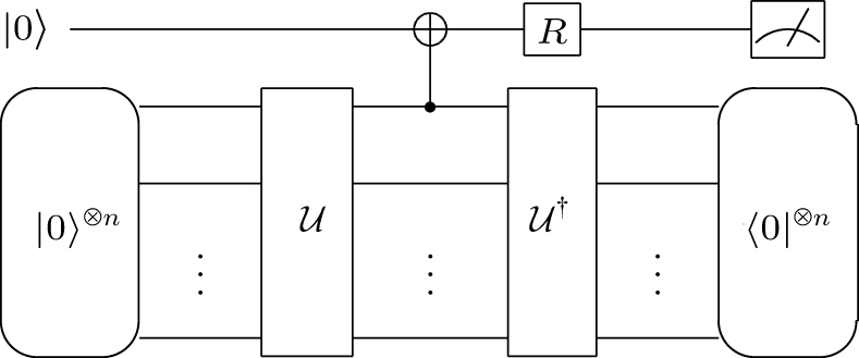
The state verification approach is to check whether or not the dual form of the state-preparation circuit can evolve the state back to its initial. We call this procedure the dual test. In practical quantum computation, the expectation of an observable is measured by averaging over many circuit executions. State verification only keeps those executions that pass the dual test and discards the rest. The state-verified circuit usually has an intermediate measurement sandwiched between the state-preparation circuit and its dual circuit. The intermediate measurement can be executed in a non-destructive manner with the aid of one auxiliary qubit. We here provide an example circuit[25] in Fig. 3. The multi-copy approach and state-verification approach can be combined[60,61] to achieve qubit overhead lower than nM + 1.
Fig. 3. An example of state verification circuit. The circuit is used to compute f′ = Tr(σzρ2)/Tr(ρ2), where and σz is the Pauli-Z operator on the first qubit of ρ, i.e., the control qubit of the CNOT gate in this figure. The qubit on the top is the ancilla and the Pauli-Z (-X) operator on the ancilla is denoted by . R can be either I or H. When R = I, we measure of the ancilla. When R = H, we can effectively measure of the ancilla by measuring in the Pauli-Z basis. The distilled result is , where 〈O〉0 denotes the expectation of O conditioned on the output state being |0〉⊗n.
Here we briefly discuss the efficacy of VD. The variance is increased by VD due to the denominator Tr(ρM) < 1. Additionally, extra circuit executions are required in practical implementations. Firstly, measurement by diagonalization may map OS(M) to the sum of several observable that can not be measured at the same time. We may have to estimate each observable individually and thus more circuit executions are needed. Secondly, state verification requires more circuit executions due to the discarding of failed trials in the dual test. The bias in VD comes from two aspects. One is due to the finite number of M, however this part of bias can be exponentially suppressed by increasing M. The other one is due to the so-called coherent mismatch[22,62] or the noise floor,[23] i.e., the difference between ρef and : Δ = 1 -– Tr(ρef| ψ0〉〈ψ0|). Suppose that ψ = (1 – ϵ)ρef + ϵρe, the coherent mismatch vanishes only if [ρef,ρe] = 0. Given in Refs. [23,62], for general states and observables, the bias caused by coherent mismatch is bounded bywhere || O ||∞ is the largest absolute eigenvalue of O.
Symmetry verification and subspace expansion
Symmetry verification and subspace expansion are used to mitigate errors in the simulation of quantum systems. When the simulated system exhibits certain symmetries, we can mitigate errors by verifying these symmetries.[20,21] In quantum subspace expansion,[26,27] we can express the Hamiltonian in an effective subspace spanned by a set of noisy quantum states and obtain the error mitigated ground energy via generalized matrix diagonalization.
Symmetry verification
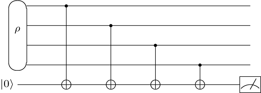
A symmetry is a unitary operator S that commutes with the system’s Hamiltonian H, i.e.,Suppose PS is the operator that projects into the subspace of symmetry S, i.e., the subspace with the right eigenvalue of S. By measuring and post-selecting those states that pass the symmetry check of S,[20,21] we can project the erroneous state ρ ontoSince ρ′ has excluded the states not lying in the subspace, it has lower error comparing with ρ. Accordingly, the error mitigation formula isi.e., with yC1 = Tr(OPSρPS) and yC2 = Tr(PSρPS). In the case of , the symmetry operator satisfies S|ψ〉 = s|ψ〉, where |ψ〉 is an arbitrary state in the subspace and s = ±1. The corresponding projector is in the form of . For example, the parity of the total electron number Ne is a symmetry if the system has a conserved number of electrons. The parity check operator PNe of the total electron number satisfies PNe|ψ〉 = s|ψ〉 for all physical states of this system and s = ± 1 depending on the parity of Ne. We can use the circuit in Fig. 4 to check the parity of the electron number. In the case that the measurement operator O commutes with the symmetry operator, we can directly measure O without the symmetry checking circuit and post-selecting those results that have the right symmetry.
Fig. 4. A symmetry verification circuit for parity check. The qubit at the bottom is the ancilla. If spin-orbitals are mapped to qubits with |1〉 (|0〉) representing occupied (unoccupied) by an electron, we can check the parity of electron numbers by measuring the ancilla.
Quantum subspace expansion
We briefly introduce quantum subspace expansion with the example of an application in solving electronic structure problems.[26,27] Suppose that the quantum circuit C can prepare the ground state on an ideal device, and on a noisy device the prepared state is |ψg〉. We choose a set of expansion operator that excites to states with higher energies. Si can be chosen as where are fermion creation and annihilation operators, which are encoded as Pauli operators on a quantum computer with methods such as Jordan–Wigner transformation. To implement the subspace expansion method, we first measure the quantities and and carry out the generalized matrix diagonalizationwhere A and B are matrices with respective entries Aij and Bij, Λ = diag(Λ1,Λ2,…,Λi,…) is a diagonal matrix of eigenvalues Λi, and Ξ is the matrix of eigenvectors. The error mitigation formula for the ground state energy is
If we choose the set of expansion operators as , quantum subspace expansion and symmetry verification are equivalent.[21] Let and . Using the expansion set , solving Eq. (47) is equivalent to diagonalizingwhereWe note that B is invertible if Tr(Sρ) ≠ 1. The eigenvalues of Eq. (49) areThe error mitigated expectation of H according to the symmetry-verification formula in Eq. (46) isSubstituting into Eq. (53) and considering [H, PS] = 0, we havewhich admits the same form as that in Eq. (52).
Symmetry expansion
Symmetry expansion[63,64] can be regarded as the general form of symmetry verification and subspace expansion using symmetry operators for expansion. The complete symmetry group of an error-free quantum state is the stabilizer group . Define the projectorwhere is a subset of the whole stabilizer group. If we choose , means no projection and error is not mitigated. If we choose , the noisy state is projected onto the intersections of all subspaces of symmetries which contain only the error-free state, and the error-free result is obtained. The practical choice of in the NISQ era, is to let be the intersection between the Pauli group and the stabilizer group, hence symmetry expansion is reduced to verify the Pauli operator symmetries.
Error mitigation using Clifford-circuit learning
The Clifford-circuit learning method was proposed by Strikis et al.[18] and Czarnik et al.[19] Generally speaking, given an error mitigation formula , Clifford circuit learning obtains the parameters by minimizing the loss functionwhere denotes average over the set , and are training circuits generated by randomly replacing all non-Clifford single-qubit gates in a circuit with Clifford gates. Here we have assumed that all multi-qubit gates are all Clifford. In Eq. (56), can be computed on the noisy quantum computer according to the formula F and can be computed on a classical computer utilizing the efficient simulation of Clifford circuits.[65]
In principle, we can take any form for F. Strikis et al.[18] took the form of PEC in Eq. (19) and addressed two issues in PEC. The first issue is, PEC according to gate-wise decomposition, cannot completely eliminate (both spacial and temporal) correlated errors among gates. The second issue is that the decomposition we find using the method in Eq. (24) is optimal for every gate, however, may not be optimal for the whole circuit. In the learning-based protocol, we can directly optimize the quasi-probability decomposition ab initio, and we take into account the joint quasi-probability among gates rather than the products of gate-wise quasi-probabilities. Therefore the two issues are addressed. It is demonstrated that the learning-based PEC is advantageous in both reducing the bias and variance comparing with the gate-wise PEC when correlated errors are significant.
Alternatively, Czarnik et al.[19] used the error-mitigation formula with two factor a and b:The corresponding loss function is . When b = 0, Eq. (57) is also the formula of error mitigation with the phenomenological error model[66] and with the global depolarizing noise.[67–69]
The efficacy of Clifford learning
The efficacy of Clifford learning lies upon two results. This first result is that we can evaluate quantum-circuit error loss by sampling Clifford circuits[70] when the error model is independent of single-qubit gates. The underlying reason is that Clifford circuits formulate a unitary-2 design,[71] hence we havewhere is the set of circuits when single-qubit gates are arbitrary unitary. When the error model depends on single-qubit gates, Eq. (58) does not hold in general. However we can still obtain a reliable estimation of the loss over unitary circuits using the method of hybrid sampling,[70] where a few gates in the circuit can be general unitaries while the other gates are all Clifford.
The second result is that, the bias can be complete eliminated in the ideal case such as when learning-based PEC finds the optimal quasi-probabilities.[18] Even for simple formulas such as that in Eq. (57), the bias is sufficiently reduced.[66,72] The results in Ref. [66] suggest that, if is optimized using Clifford circuits, it holds thatwhere N is the number of gates.
Sampling Clifford circuits is efficient if we use the importance Clifford sampling technique.[66] Suppose that the observable is a Pauli operator, the error-free result of a Clifford circuit is either 0 or ±1. These Clifford circuits whose error-free results are zero do not contribute to the loss in Eq. (56), because their erroneous results are also zero when subjected to Pauli errors. For example, ρef is an error-free final state of a Clifford circuit with Tr(Oρef) = 0. When subjected to a depolarizing channel, the erroneous final state is , where α is the depolarizing rate, whose expected output is also zero. Importance Clifford sampling efficiently produces Clifford circuits with ±1 outcomes, thus the loss can be efficiently estimated.
Combined methods
Multiple error mitigation methods can be used in combination when quantum computing with one method individually can not achieve a satisfactory accuracy. We can in principle take the output of one error-mitigated method as the input of another. For any two error mitigation formulas F1 and F2, the concatenated formula iswhere is the error mitigated result according to the formula F1. We can also concatenate multiple formulas in the same way. Next, we briefly introduce the combined methods proposed in literature.
Symmetry verification can be used in combination with error extrapolation and probabilistic error cancellation.[32] Symmetry verification has its limitations since those errors that commute with the symmetry operator can not be mitigated. Thus, it is natural to use other methods to mitigate the remaining errors. For example, we can replace yC(ϵj) in Eq. (3) with the symmetry verified result according to the formula in Eq. (46) and the error mitigation formula becomes
Probabilistic error cancellation and error extrapolation can also be used in combination.[32,73] We can use error extrapolation to determine the gate-wise decomposition in Eq. (20) for noise-agnostic gates, i.e., we can replace with the error-boosted gate and determine the quasi-probabilities λi,βi using the error extrapolation method. On the other hand, if we have the tomographic knowledge on the noise operations, we can use PEC to effectively decrease the noise rate. We can use the results at several different decreased noise rates as the data points in error extrapolation. For example, in Eq. (3), ϵj can be considered as the j-th error rate reduced using PEC.
The framework of generalized subspace expansion[74] enables us to take the outputs of error extrapolation and virtual distillation as the inputs of subspace expansion. The general framework permits us to write the entries of A in Eq. (47) as Aij = Tr(ρ(i)ρ(j)H). We can let ρ(i) be either the output of virtual distillation with i copies, or the output of i-th error-boosted quantum circuit.
All kinds of methods can be used in combination with Clifford-circuit learning.[66,75] For example, given a two-points error extrapolation formulawe can use the Clifford-circuit learning method to determine the parameter λ. Another example is, we can always take the error mitigated result as the input of Clifford circuit learning. Supposing that is the error-mitigated result via PEC or virtual distillation, we can further improve the result by , where a is determined using Clifford-circuit learning.
Summary
In this paper, we provide a thorough overview of the state-of-the-art QEM methods in a general form, where each method is expressed as an error mitigation formula. With the formula, we can concatenate any two or more QEM methods by replacing the input y to the high-level method with output f′ of the low-level method. The formula can be further optimized with lower bias and variance using the Clifford-circuit learning method, where the formula is written as a parameterized function.
Note that the qubit cost and implementation complexity are not reflected in the error mitigation formula. The efficiency of some methods, for instances PEC and Clifford circuit sampling, is maximized under the assumption of sampling random circuits. Random circuit sampling is necessary in Pauli twirling to convert general errors into Pauli errors, which have favorable properties in QEM. In this regard, some QEM methods are easier to implement. For example, as error extrapolation requires no random circuit sampling, it can be implemented with only a few circuits.
The bias and the variance of the QEM estimator depend on the error mitigation formula and estimator of each yC. In general, there is room to optimize yC estimators to maximize the performance of QEM. For example, in PEC, circuit executions are allocated according to importance sampling. With the QEM formula, we can analyze the bias and the variance using the standard approach, e.g., propagation of uncertainty.
Error mitigation methods are important for quantum computing on NISQ devices. Compared with QEC, QEM can work in quantum circuits with high error rates. On the other hand, as the variance increases with the circuit size, more sampling and circuit executions are required to reduce the variance, thus QEM is not as scalable as QEC. However, as the QEM technique continuously evolves, we anticipate some benchmarking tools to be developed to reduce the circuit execution overhead. Meanwhile, QEM could be used in part of QEC to reduce the qubit cost when fault-tolerant technology becomes available.[76–79]
Acknowledgments
This work is supported by the National Natural Science Foundation of China (Grant Nos. 11875050 and 12088101) and NSAF (Grant No. U1930403).
Giurgica-TironTHindyYLaRoseRMariAZengW J2020IEEE International Conference on Quantum Computing and Engineering (QCE)October 12–16, 2020Denver, CO, USA306316
... As the name suggests, QEM methods are designed for mitigating the effect of errors instead of correcting them. They can work in a quantum circuit with an error rate higher than the threshold of QEC, without the large qubit overhead. Therefore, QEM is suitable for quantum devices in the noisy intermediate-scale quantum (NISQ) era,[8] a midway towards fault-tolerant quantum computers[9] in which quantum computing is fully protected by QEC. NISQ devices have only dozens to hundreds of qubits, nevertheless, they have demonstrated the quantum advantage on a specific problem,[4,10] and it is believed that they can retain this advantage to solve practical problems. To achieve this goal, many quantum algorithms[11,12] have been proposed. Incorporating QEM methods is essential for certain applications on NISQ devices. ...
... Since the rate of measurement errors is larger than that of two-qubit gate errors in some systems,[4,10] it is crucial to mitigate measurement errors. The widely discussed method to mitigate measurement errors is post-processing according to the results of quantum detector tomography.[52–54] ...
1
2020
... As the name suggests, QEM methods are designed for mitigating the effect of errors instead of correcting them. They can work in a quantum circuit with an error rate higher than the threshold of QEC, without the large qubit overhead. Therefore, QEM is suitable for quantum devices in the noisy intermediate-scale quantum (NISQ) era,[8] a midway towards fault-tolerant quantum computers[9] in which quantum computing is fully protected by QEC. NISQ devices have only dozens to hundreds of qubits, nevertheless, they have demonstrated the quantum advantage on a specific problem,[4,10] and it is believed that they can retain this advantage to solve practical problems. To achieve this goal, many quantum algorithms[11,12] have been proposed. Incorporating QEM methods is essential for certain applications on NISQ devices. ...
1
2022
... As the name suggests, QEM methods are designed for mitigating the effect of errors instead of correcting them. They can work in a quantum circuit with an error rate higher than the threshold of QEC, without the large qubit overhead. Therefore, QEM is suitable for quantum devices in the noisy intermediate-scale quantum (NISQ) era,[8] a midway towards fault-tolerant quantum computers[9] in which quantum computing is fully protected by QEC. NISQ devices have only dozens to hundreds of qubits, nevertheless, they have demonstrated the quantum advantage on a specific problem,[4,10] and it is believed that they can retain this advantage to solve practical problems. To achieve this goal, many quantum algorithms[11,12] have been proposed. Incorporating QEM methods is essential for certain applications on NISQ devices. ...
3
2017
... Various QEM methods have been proposed. In methods such as error extrapolation (or zero-noise extrapolation)[13,14] and probabilistic error cancellation (PEC),[14,15] given some knowledge about the noise, we can compensate errors and make the computing result closer to the true value. These methods do not require additional qubits. The knowledge of the noise, e.g., a parameter such as the error rate or a concrete error model, can be obtained with some characterization methods.[16,17] Alternatively, the parameters used in QEM protocols can be optimized in a learning-based or data-driven manner.[18,19] In symmetry verification[20,21] and virtual distillation,[22–25] errors are eliminated based on certain constrains on the quantum state, i.e., symmetry and purity, respectively. Multiple copies of the noisy state are required for effectively increasing the purity in virtual distillation. These methods are more similar to QEC than error extrapolation and PEC: In a QEC code, a symmetry (i.e., the stabilizer group in stabilizer codes) is constructed at the cost of qubit overhead. In addition to general-purpose QEM methods, protocols are also developed for specific algorithms.[26–28] For example, the quantum subspace expansion[26,27] is a protocol designed to reduce errors in a variational quantum eigensolver.[29] ...
... The idea of error extrapolation was introduced in works by Li and benjamin[13] and Temme et al.,[14] in which the polynomial fitting function is considered. It is assumed that the erroneous result can be expressed with the polynomial decompositionwhere ϵ is the total error rate of gates in the circuit. Executing the quantum circuit with l (≤ m + 1) different error rates, we can eliminate the first m-th order effects of noise using an m-order polynomial fitting. ...
... The first method takes use of Pauli twirling and random Pauli gate insertion.[13] This method relies on the assumption that quantum errors of the single-qubit gates can be ignored comparing with those of multi-qubit gates. We can effectively increase the error via randomly inserting Pauli gates after each multi-qubit gate. Pauli twirling converts an arbitrary noise channel into Pauli noise:[36]where σi,σj ∈ {σI,σx, σy, σz} are single-qubit Pauli operators and σiσj denotes a tensor product. Pij are positive coefficients satisfying Σi,jPij = 1. To implement the Pauli twirling technique, we randomly insert Pauli gates before and after , resulting in , where σa and σb are uniformly sampled from {σI,σx, σy, σz} and accordingly σd σc = [Ui]σbσa. To boost up the error rate, a further step is to randomly insert Pauli gates after each multi-qubit gate. Recall Eq. (9) and assume a small error rate, randomly inserting each Pauli gate σiσj with a probability of rPi,j can boost the error rate from ϵ to (1 + r)ϵ. ...
6
2017
... Various QEM methods have been proposed. In methods such as error extrapolation (or zero-noise extrapolation)[13,14] and probabilistic error cancellation (PEC),[14,15] given some knowledge about the noise, we can compensate errors and make the computing result closer to the true value. These methods do not require additional qubits. The knowledge of the noise, e.g., a parameter such as the error rate or a concrete error model, can be obtained with some characterization methods.[16,17] Alternatively, the parameters used in QEM protocols can be optimized in a learning-based or data-driven manner.[18,19] In symmetry verification[20,21] and virtual distillation,[22–25] errors are eliminated based on certain constrains on the quantum state, i.e., symmetry and purity, respectively. Multiple copies of the noisy state are required for effectively increasing the purity in virtual distillation. These methods are more similar to QEC than error extrapolation and PEC: In a QEC code, a symmetry (i.e., the stabilizer group in stabilizer codes) is constructed at the cost of qubit overhead. In addition to general-purpose QEM methods, protocols are also developed for specific algorithms.[26–28] For example, the quantum subspace expansion[26,27] is a protocol designed to reduce errors in a variational quantum eigensolver.[29] ...
... [14,15] given some knowledge about the noise, we can compensate errors and make the computing result closer to the true value. These methods do not require additional qubits. The knowledge of the noise, e.g., a parameter such as the error rate or a concrete error model, can be obtained with some characterization methods.[16,17] Alternatively, the parameters used in QEM protocols can be optimized in a learning-based or data-driven manner.[18,19] In symmetry verification[20,21] and virtual distillation,[22–25] errors are eliminated based on certain constrains on the quantum state, i.e., symmetry and purity, respectively. Multiple copies of the noisy state are required for effectively increasing the purity in virtual distillation. These methods are more similar to QEC than error extrapolation and PEC: In a QEC code, a symmetry (i.e., the stabilizer group in stabilizer codes) is constructed at the cost of qubit overhead. In addition to general-purpose QEM methods, protocols are also developed for specific algorithms.[26–28] For example, the quantum subspace expansion[26,27] is a protocol designed to reduce errors in a variational quantum eigensolver.[29] ...
... The idea of error extrapolation was introduced in works by Li and benjamin[13] and Temme et al.,[14] in which the polynomial fitting function is considered. It is assumed that the erroneous result can be expressed with the polynomial decompositionwhere ϵ is the total error rate of gates in the circuit. Executing the quantum circuit with l (≤ m + 1) different error rates, we can eliminate the first m-th order effects of noise using an m-order polynomial fitting. ...
... The third method is stretching the Hamiltonian. On realistic quantum hardware, quantum gates are implemented by evolving qubits’ state under a controlled time-dependent Hamiltonian denoted by H(t). The stretched Hamiltonian H(t/r)/r can increase the error rate by a multiplicative factor of r under the assumption that the noise generator is independent of the Hamiltonian and constant in time.[14] In experiments, we can realize the stretched Hamiltonian by reducing the pulse strength that controls the qubits while prolonging the pulse time. An illustrative example is, similar to the Rabi stretch for single-qubit in Ref. [41], a spin initialized in the Z-direction evolving under a X-direction magnetic field H = Bσx(t). The method of stretching the Hamiltonian here is to increase the duration t and reduce the field strength B by the same multiple. A more practical example is given in Ref. [42], where it tunes the cross-resonance pulse on a superconducting quantum processor. ...
... Probabilistic error cancellation (PEC) was proposed by Temme et al.,[14] which is implemented based on a quasi-probability decomposition. A practical method of constructing the formula using gate set tomography and universal gate set was introduced by Endo et al.[15] The basic idea is that an error-free operation can be expressed as a linear combination of erroneous ones. Suppose that the vector β = (β1, β2, …, βN) specifies a quantum circuit (βi specifies the i-th gate) and there exists a circuit decomposition , the error cancellation formula iswhere . ...
... The sampling overhead depends on the choice of decomposition basis set. For a general noise channel, we can always decompose its inverse with the universal basis set[15] despite that it may not be optimal, i.e., there may exit other decomposition sets, with which we can achieve lower sampling overhead. One example given by Takagi[47] is the cancellation of the general dephasing noise where . It is shown that, when , the sampling overhead is with the universal basis set, while the optimal overhead is γopt = 1/(1 – 2ϵ) with the basis . Indeed we can achieve the optimal overhead if we use a flexible decomposition set. One method to find the optimal decomposition set is by the method of constraint optimization.[14,48,49] Realistic quantum noise is complete-positive and trace-preserving (CPTP). As given in Ref. [49], the inverse of a CPTP map is Hermitian-preserving and trace-preserving (HPTP), and there exists the following decomposition:where is a HPTP map, are CPTP maps, and λ1,λ2 ≥ 0 are two real numbers. According to Eq. (23), we can employ the following constraint optimization to determine the optimal resource cost:where is the Choi-Jamiolkowski isomorphism of Λ and TrB denotes the partial trace over the subsystem B. Equation (26) comes from trace preservation, equation (27) comes from complete positivity and equation (28) comes from the Hermitian preservation of . The physical implementation of a CPTP map such as can be realized on a quantum computer with at most extra n qubits according to the theorem of Stinespring dilation.[48] ...
7
2018
... Various QEM methods have been proposed. In methods such as error extrapolation (or zero-noise extrapolation)[13,14] and probabilistic error cancellation (PEC),[14,15] given some knowledge about the noise, we can compensate errors and make the computing result closer to the true value. These methods do not require additional qubits. The knowledge of the noise, e.g., a parameter such as the error rate or a concrete error model, can be obtained with some characterization methods.[16,17] Alternatively, the parameters used in QEM protocols can be optimized in a learning-based or data-driven manner.[18,19] In symmetry verification[20,21] and virtual distillation,[22–25] errors are eliminated based on certain constrains on the quantum state, i.e., symmetry and purity, respectively. Multiple copies of the noisy state are required for effectively increasing the purity in virtual distillation. These methods are more similar to QEC than error extrapolation and PEC: In a QEC code, a symmetry (i.e., the stabilizer group in stabilizer codes) is constructed at the cost of qubit overhead. In addition to general-purpose QEM methods, protocols are also developed for specific algorithms.[26–28] For example, the quantum subspace expansion[26,27] is a protocol designed to reduce errors in a variational quantum eigensolver.[29] ...
... In some cases, the exponential extrapolation proposed by Endo et al.[15] has advantages in accuracy. The simplest exponential extrapolation isgiven two error rates ϵ0 < ϵ1. Giurgica-Tiron et al.[31] summarized the extrapolation formulas and introduced a more general form of poly-exponential extrapolation, in which the logarithm of erroneous result fits to a polynomial function. Cai[32] generalized error extrapolation to the multi-exponential functions where the sum of exponents is the fitting function. ...
... The advantage of exponential extrapolation is analyzed by Endo et al.[15] and Cai.[32] Here we briefly summarize the results. In the circuit model, the number of locations prone to errors equals to the number of gates. With a sufficiently large number of gates, the probability of errors occurring at l locations satisfies the Poisson distribution , where μ is the average number of error-occurred locations. Assuming that the occurred error will move the measured expectation towards zero with a probability of α, the erroneous result isand in the N → ∞ limit it becomes an exponential function fCe−μα. The advantage of exponential extrapolation is numerically demonstrated in Refs. [15,31]. Observations of the fidelity decay in experiments, e.g., the results in Ref. [33], also support this conclusion. ...
... . The advantage of exponential extrapolation is numerically demonstrated in Refs. [15,31]. Observations of the fidelity decay in experiments, e.g., the results in Ref. [33], also support this conclusion. ...
... Probabilistic error cancellation (PEC) was proposed by Temme et al.,[14] which is implemented based on a quasi-probability decomposition. A practical method of constructing the formula using gate set tomography and universal gate set was introduced by Endo et al.[15] The basic idea is that an error-free operation can be expressed as a linear combination of erroneous ones. Suppose that the vector β = (β1, β2, …, βN) specifies a quantum circuit (βi specifies the i-th gate) and there exists a circuit decomposition , the error cancellation formula iswhere . ...
... The inverse of typical error models, such as depolarizing and dephasing, can be decomposed with Pauli basis σβi ∈ {σI,σx,σy,σz}. For a general error model, the decomposition basis is a larger gate set[15] whose elements can be synthesized with Clifford gates and the projection operator . ...
... The sampling overhead depends on the choice of decomposition basis set. For a general noise channel, we can always decompose its inverse with the universal basis set[15] despite that it may not be optimal, i.e., there may exit other decomposition sets, with which we can achieve lower sampling overhead. One example given by Takagi[47] is the cancellation of the general dephasing noise where . It is shown that, when , the sampling overhead is with the universal basis set, while the optimal overhead is γopt = 1/(1 – 2ϵ) with the basis . Indeed we can achieve the optimal overhead if we use a flexible decomposition set. One method to find the optimal decomposition set is by the method of constraint optimization.[14,48,49] Realistic quantum noise is complete-positive and trace-preserving (CPTP). As given in Ref. [49], the inverse of a CPTP map is Hermitian-preserving and trace-preserving (HPTP), and there exists the following decomposition:where is a HPTP map, are CPTP maps, and λ1,λ2 ≥ 0 are two real numbers. According to Eq. (23), we can employ the following constraint optimization to determine the optimal resource cost:where is the Choi-Jamiolkowski isomorphism of Λ and TrB denotes the partial trace over the subsystem B. Equation (26) comes from trace preservation, equation (27) comes from complete positivity and equation (28) comes from the Hermitian preservation of . The physical implementation of a CPTP map such as can be realized on a quantum computer with at most extra n qubits according to the theorem of Stinespring dilation.[48] ...
1
2011
... Various QEM methods have been proposed. In methods such as error extrapolation (or zero-noise extrapolation)[13,14] and probabilistic error cancellation (PEC),[14,15] given some knowledge about the noise, we can compensate errors and make the computing result closer to the true value. These methods do not require additional qubits. The knowledge of the noise, e.g., a parameter such as the error rate or a concrete error model, can be obtained with some characterization methods.[16,17] Alternatively, the parameters used in QEM protocols can be optimized in a learning-based or data-driven manner.[18,19] In symmetry verification[20,21] and virtual distillation,[22–25] errors are eliminated based on certain constrains on the quantum state, i.e., symmetry and purity, respectively. Multiple copies of the noisy state are required for effectively increasing the purity in virtual distillation. These methods are more similar to QEC than error extrapolation and PEC: In a QEC code, a symmetry (i.e., the stabilizer group in stabilizer codes) is constructed at the cost of qubit overhead. In addition to general-purpose QEM methods, protocols are also developed for specific algorithms.[26–28] For example, the quantum subspace expansion[26,27] is a protocol designed to reduce errors in a variational quantum eigensolver.[29] ...
3
2015
... Various QEM methods have been proposed. In methods such as error extrapolation (or zero-noise extrapolation)[13,14] and probabilistic error cancellation (PEC),[14,15] given some knowledge about the noise, we can compensate errors and make the computing result closer to the true value. These methods do not require additional qubits. The knowledge of the noise, e.g., a parameter such as the error rate or a concrete error model, can be obtained with some characterization methods.[16,17] Alternatively, the parameters used in QEM protocols can be optimized in a learning-based or data-driven manner.[18,19] In symmetry verification[20,21] and virtual distillation,[22–25] errors are eliminated based on certain constrains on the quantum state, i.e., symmetry and purity, respectively. Multiple copies of the noisy state are required for effectively increasing the purity in virtual distillation. These methods are more similar to QEC than error extrapolation and PEC: In a QEC code, a symmetry (i.e., the stabilizer group in stabilizer codes) is constructed at the cost of qubit overhead. In addition to general-purpose QEM methods, protocols are also developed for specific algorithms.[26–28] For example, the quantum subspace expansion[26,27] is a protocol designed to reduce errors in a variational quantum eigensolver.[29] ...
... Truncated Neumann series Recently, Wang et al.[30] proposed error mitigation with truncated Neumann series. In this protocol, a formula resembling that in Eq. (3) is used, but the parameters are determined according to the truncated Neumann series. Let be a linear map from a super-operator , which is a squared matrix in the Pauli transfer matrix representation,[17] to the real field . Under the condition of , which can be satisfied if in some consistent norm, it holds thatwhere , and is the binomial coefficient. The proof of Eq. (5) can be found in Appendix B of Ref. [30]. Suppose , where is the overall noise effect and [U] prepares the error-free state . Replacing with and with in Eq. (5), we haveHere can be realized by repeatedly applying for k times. The bias in Eq. (6) decays exponentially with k when the error rate is small. ...
... Here we briefly discuss the advantages and disadvantages of these three error-boosting methods. The first method requires accurate understanding of the error model, and the error rate is boosted in a pseudo manner, i.e., the error rate is not actually increased but the collective result of random circuits is equal to the result on an error-increased device. The advantage is that, with the aid of reliable gate benchmarking methods such as gate set tomography,[17] the critical condition that boosting error will not change the error model can be fulfilled. The second method is easy to implement. Comparing with the first one, the second method does not need any definite knowledge about the noise model. However, it is at greater risk that the error model is changed when folding gates. This is not a serious problem when with only simple error models such as depolarizing. In general, it may cause that, quoted from Ref. [5], “arbitrarily deviate from the desired result when only slightly more complicated error models are considered”. Both the first and second methods are in the digital level and friendly to cloud-platform users, while the third method requires direct control of the underlying quantum hardware. Nevertheless, pulse-level control is accessible through some hardware providers.[43,44] As shown in the work of Schultz et al.,[40] the amount of increased noise by different methods depends on the time-correlation. The performance of different methods is similar with white noise, but can be significantly different for time-correlated noise. ...
4
2021
... Various QEM methods have been proposed. In methods such as error extrapolation (or zero-noise extrapolation)[13,14] and probabilistic error cancellation (PEC),[14,15] given some knowledge about the noise, we can compensate errors and make the computing result closer to the true value. These methods do not require additional qubits. The knowledge of the noise, e.g., a parameter such as the error rate or a concrete error model, can be obtained with some characterization methods.[16,17] Alternatively, the parameters used in QEM protocols can be optimized in a learning-based or data-driven manner.[18,19] In symmetry verification[20,21] and virtual distillation,[22–25] errors are eliminated based on certain constrains on the quantum state, i.e., symmetry and purity, respectively. Multiple copies of the noisy state are required for effectively increasing the purity in virtual distillation. These methods are more similar to QEC than error extrapolation and PEC: In a QEC code, a symmetry (i.e., the stabilizer group in stabilizer codes) is constructed at the cost of qubit overhead. In addition to general-purpose QEM methods, protocols are also developed for specific algorithms.[26–28] For example, the quantum subspace expansion[26,27] is a protocol designed to reduce errors in a variational quantum eigensolver.[29] ...
... The Clifford-circuit learning method was proposed by Strikis et al.[18] and Czarnik et al.[19] Generally speaking, given an error mitigation formula , Clifford circuit learning obtains the parameters by minimizing the loss functionwhere denotes average over the set , and are training circuits generated by randomly replacing all non-Clifford single-qubit gates in a circuit with Clifford gates. Here we have assumed that all multi-qubit gates are all Clifford. In Eq. (56), can be computed on the noisy quantum computer according to the formula F and can be computed on a classical computer utilizing the efficient simulation of Clifford circuits.[65] ...
... In principle, we can take any form for F. Strikis et al.[18] took the form of PEC in Eq. (19) and addressed two issues in PEC. The first issue is, PEC according to gate-wise decomposition, cannot completely eliminate (both spacial and temporal) correlated errors among gates. The second issue is that the decomposition we find using the method in Eq. (24) is optimal for every gate, however, may not be optimal for the whole circuit. In the learning-based protocol, we can directly optimize the quasi-probability decomposition ab initio, and we take into account the joint quasi-probability among gates rather than the products of gate-wise quasi-probabilities. Therefore the two issues are addressed. It is demonstrated that the learning-based PEC is advantageous in both reducing the bias and variance comparing with the gate-wise PEC when correlated errors are significant. ...
... The second result is that, the bias can be complete eliminated in the ideal case such as when learning-based PEC finds the optimal quasi-probabilities.[18] Even for simple formulas such as that in Eq. (57), the bias is sufficiently reduced.[66,72] The results in Ref. [66] suggest that, if is optimized using Clifford circuits, it holds thatwhere N is the number of gates. ...
3
2020
... Various QEM methods have been proposed. In methods such as error extrapolation (or zero-noise extrapolation)[13,14] and probabilistic error cancellation (PEC),[14,15] given some knowledge about the noise, we can compensate errors and make the computing result closer to the true value. These methods do not require additional qubits. The knowledge of the noise, e.g., a parameter such as the error rate or a concrete error model, can be obtained with some characterization methods.[16,17] Alternatively, the parameters used in QEM protocols can be optimized in a learning-based or data-driven manner.[18,19] In symmetry verification[20,21] and virtual distillation,[22–25] errors are eliminated based on certain constrains on the quantum state, i.e., symmetry and purity, respectively. Multiple copies of the noisy state are required for effectively increasing the purity in virtual distillation. These methods are more similar to QEC than error extrapolation and PEC: In a QEC code, a symmetry (i.e., the stabilizer group in stabilizer codes) is constructed at the cost of qubit overhead. In addition to general-purpose QEM methods, protocols are also developed for specific algorithms.[26–28] For example, the quantum subspace expansion[26,27] is a protocol designed to reduce errors in a variational quantum eigensolver.[29] ...
... The Clifford-circuit learning method was proposed by Strikis et al.[18] and Czarnik et al.[19] Generally speaking, given an error mitigation formula , Clifford circuit learning obtains the parameters by minimizing the loss functionwhere denotes average over the set , and are training circuits generated by randomly replacing all non-Clifford single-qubit gates in a circuit with Clifford gates. Here we have assumed that all multi-qubit gates are all Clifford. In Eq. (56), can be computed on the noisy quantum computer according to the formula F and can be computed on a classical computer utilizing the efficient simulation of Clifford circuits.[65] ...
... Alternatively, Czarnik et al.[19] used the error-mitigation formula with two factor a and b:The corresponding loss function is . When b = 0, Eq. (57) is also the formula of error mitigation with the phenomenological error model[66] and with the global depolarizing noise.[67–69] ...
3
2019
... Various QEM methods have been proposed. In methods such as error extrapolation (or zero-noise extrapolation)[13,14] and probabilistic error cancellation (PEC),[14,15] given some knowledge about the noise, we can compensate errors and make the computing result closer to the true value. These methods do not require additional qubits. The knowledge of the noise, e.g., a parameter such as the error rate or a concrete error model, can be obtained with some characterization methods.[16,17] Alternatively, the parameters used in QEM protocols can be optimized in a learning-based or data-driven manner.[18,19] In symmetry verification[20,21] and virtual distillation,[22–25] errors are eliminated based on certain constrains on the quantum state, i.e., symmetry and purity, respectively. Multiple copies of the noisy state are required for effectively increasing the purity in virtual distillation. These methods are more similar to QEC than error extrapolation and PEC: In a QEC code, a symmetry (i.e., the stabilizer group in stabilizer codes) is constructed at the cost of qubit overhead. In addition to general-purpose QEM methods, protocols are also developed for specific algorithms.[26–28] For example, the quantum subspace expansion[26,27] is a protocol designed to reduce errors in a variational quantum eigensolver.[29] ...
... Symmetry verification and subspace expansion are used to mitigate errors in the simulation of quantum systems. When the simulated system exhibits certain symmetries, we can mitigate errors by verifying these symmetries.[20,21] In quantum subspace expansion,[26,27] we can express the Hamiltonian in an effective subspace spanned by a set of noisy quantum states and obtain the error mitigated ground energy via generalized matrix diagonalization. ...
... A symmetry is a unitary operator S that commutes with the system’s Hamiltonian H, i.e.,Suppose PS is the operator that projects into the subspace of symmetry S, i.e., the subspace with the right eigenvalue of S. By measuring and post-selecting those states that pass the symmetry check of S,[20,21] we can project the erroneous state ρ ontoSince ρ′ has excluded the states not lying in the subspace, it has lower error comparing with ρ. Accordingly, the error mitigation formula isi.e., with yC1 = Tr(OPSρPS) and yC2 = Tr(PSρPS). In the case of , the symmetry operator satisfies S|ψ〉 = s|ψ〉, where |ψ〉 is an arbitrary state in the subspace and s = ±1. The corresponding projector is in the form of . For example, the parity of the total electron number Ne is a symmetry if the system has a conserved number of electrons. The parity check operator PNe of the total electron number satisfies PNe|ψ〉 = s|ψ〉 for all physical states of this system and s = ± 1 depending on the parity of Ne. We can use the circuit in Fig. 4 to check the parity of the electron number. In the case that the measurement operator O commutes with the symmetry operator, we can directly measure O without the symmetry checking circuit and post-selecting those results that have the right symmetry. ...
4
2018
... Various QEM methods have been proposed. In methods such as error extrapolation (or zero-noise extrapolation)[13,14] and probabilistic error cancellation (PEC),[14,15] given some knowledge about the noise, we can compensate errors and make the computing result closer to the true value. These methods do not require additional qubits. The knowledge of the noise, e.g., a parameter such as the error rate or a concrete error model, can be obtained with some characterization methods.[16,17] Alternatively, the parameters used in QEM protocols can be optimized in a learning-based or data-driven manner.[18,19] In symmetry verification[20,21] and virtual distillation,[22–25] errors are eliminated based on certain constrains on the quantum state, i.e., symmetry and purity, respectively. Multiple copies of the noisy state are required for effectively increasing the purity in virtual distillation. These methods are more similar to QEC than error extrapolation and PEC: In a QEC code, a symmetry (i.e., the stabilizer group in stabilizer codes) is constructed at the cost of qubit overhead. In addition to general-purpose QEM methods, protocols are also developed for specific algorithms.[26–28] For example, the quantum subspace expansion[26,27] is a protocol designed to reduce errors in a variational quantum eigensolver.[29] ...
... Symmetry verification and subspace expansion are used to mitigate errors in the simulation of quantum systems. When the simulated system exhibits certain symmetries, we can mitigate errors by verifying these symmetries.[20,21] In quantum subspace expansion,[26,27] we can express the Hamiltonian in an effective subspace spanned by a set of noisy quantum states and obtain the error mitigated ground energy via generalized matrix diagonalization. ...
... A symmetry is a unitary operator S that commutes with the system’s Hamiltonian H, i.e.,Suppose PS is the operator that projects into the subspace of symmetry S, i.e., the subspace with the right eigenvalue of S. By measuring and post-selecting those states that pass the symmetry check of S,[20,21] we can project the erroneous state ρ ontoSince ρ′ has excluded the states not lying in the subspace, it has lower error comparing with ρ. Accordingly, the error mitigation formula isi.e., with yC1 = Tr(OPSρPS) and yC2 = Tr(PSρPS). In the case of , the symmetry operator satisfies S|ψ〉 = s|ψ〉, where |ψ〉 is an arbitrary state in the subspace and s = ±1. The corresponding projector is in the form of . For example, the parity of the total electron number Ne is a symmetry if the system has a conserved number of electrons. The parity check operator PNe of the total electron number satisfies PNe|ψ〉 = s|ψ〉 for all physical states of this system and s = ± 1 depending on the parity of Ne. We can use the circuit in Fig. 4 to check the parity of the electron number. In the case that the measurement operator O commutes with the symmetry operator, we can directly measure O without the symmetry checking circuit and post-selecting those results that have the right symmetry. ...
... If we choose the set of expansion operators as , quantum subspace expansion and symmetry verification are equivalent.[21] Let and . Using the expansion set , solving Eq. (47) is equivalent to diagonalizingwhereWe note that B is invertible if Tr(Sρ) ≠ 1. The eigenvalues of Eq. (49) areThe error mitigated expectation of H according to the symmetry-verification formula in Eq. (46) isSubstituting into Eq. (53) and considering [H, PS] = 0, we havewhich admits the same form as that in Eq. (52). ...
6
2021
... Various QEM methods have been proposed. In methods such as error extrapolation (or zero-noise extrapolation)[13,14] and probabilistic error cancellation (PEC),[14,15] given some knowledge about the noise, we can compensate errors and make the computing result closer to the true value. These methods do not require additional qubits. The knowledge of the noise, e.g., a parameter such as the error rate or a concrete error model, can be obtained with some characterization methods.[16,17] Alternatively, the parameters used in QEM protocols can be optimized in a learning-based or data-driven manner.[18,19] In symmetry verification[20,21] and virtual distillation,[22–25] errors are eliminated based on certain constrains on the quantum state, i.e., symmetry and purity, respectively. Multiple copies of the noisy state are required for effectively increasing the purity in virtual distillation. These methods are more similar to QEC than error extrapolation and PEC: In a QEC code, a symmetry (i.e., the stabilizer group in stabilizer codes) is constructed at the cost of qubit overhead. In addition to general-purpose QEM methods, protocols are also developed for specific algorithms.[26–28] For example, the quantum subspace expansion[26,27] is a protocol designed to reduce errors in a variational quantum eigensolver.[29] ...
... Recently, various virtual distillation (VD) methods were proposed in several works. We categorize these methods into two kinds: the multi-copy approach[22,23] and the state verification approach.[24,25] ...
... VD estimates the numerator and denominator in Eq. (41) separately. The multi-copy approach utilizeswhere the observable O is on one of the copies and S(M) is the cyclic permutation operator, i.e., S(M) |ψ1〉 |ψ2〉 ⋅ |ψM〉 = |ψ2〉 |ψ3〉 … |ψ1〉. We can verify Eq. (42) by explicitly writing both the left- and right-hand sides into summations of matrix entries, while here we provide an intuitive interpretation given by Koczor.[22] Suppose there are M = 2 copies of states prepared as |ψ〉 |ψ〉. If any one of the two copies is flipped (due to an error) to an orthogonal state , measuring the operator OS(2) will yield , thus the contribution of the error vanishes in the purified expectation. To compute the right-hand side of Eq. (42), we can prepare M copies of the erroneous state and measure the expectation of OS(M). To measure the expectation, one approach is measurement by diagonalization,[23] i.e., we can append extra gates to the end of the original circuit to transform OS(M) into a sum of measurable observables. The transformation procedure is practical when the number of copies M is small, since S(M) can be represented as tensor products of qubit-wise permutation operators which lies in 2M-dimensional Hilbert space. The other way to measure the expectation of OS(M) is by utilizing the Hadamard-test technique.[22,59] We here provide an example circuit[22] in Fig. 2 ...
... [22,59] We here provide an example circuit[22] in Fig. 2 ...
... [22] in Fig. 2 ...
... Here we briefly discuss the efficacy of VD. The variance is increased by VD due to the denominator Tr(ρM) < 1. Additionally, extra circuit executions are required in practical implementations. Firstly, measurement by diagonalization may map OS(M) to the sum of several observable that can not be measured at the same time. We may have to estimate each observable individually and thus more circuit executions are needed. Secondly, state verification requires more circuit executions due to the discarding of failed trials in the dual test. The bias in VD comes from two aspects. One is due to the finite number of M, however this part of bias can be exponentially suppressed by increasing M. The other one is due to the so-called coherent mismatch[22,62] or the noise floor,[23] i.e., the difference between ρef and : Δ = 1 -– Tr(ρef| ψ0〉〈ψ0|). Suppose that ψ = (1 – ϵ)ρef + ϵρe, the coherent mismatch vanishes only if [ρef,ρe] = 0. Given in Refs. [23,62], for general states and observables, the bias caused by coherent mismatch is bounded bywhere || O ||∞ is the largest absolute eigenvalue of O. ...
4
2021
... Recently, various virtual distillation (VD) methods were proposed in several works. We categorize these methods into two kinds: the multi-copy approach[22,23] and the state verification approach.[24,25] ...
... VD estimates the numerator and denominator in Eq. (41) separately. The multi-copy approach utilizeswhere the observable O is on one of the copies and S(M) is the cyclic permutation operator, i.e., S(M) |ψ1〉 |ψ2〉 ⋅ |ψM〉 = |ψ2〉 |ψ3〉 … |ψ1〉. We can verify Eq. (42) by explicitly writing both the left- and right-hand sides into summations of matrix entries, while here we provide an intuitive interpretation given by Koczor.[22] Suppose there are M = 2 copies of states prepared as |ψ〉 |ψ〉. If any one of the two copies is flipped (due to an error) to an orthogonal state , measuring the operator OS(2) will yield , thus the contribution of the error vanishes in the purified expectation. To compute the right-hand side of Eq. (42), we can prepare M copies of the erroneous state and measure the expectation of OS(M). To measure the expectation, one approach is measurement by diagonalization,[23] i.e., we can append extra gates to the end of the original circuit to transform OS(M) into a sum of measurable observables. The transformation procedure is practical when the number of copies M is small, since S(M) can be represented as tensor products of qubit-wise permutation operators which lies in 2M-dimensional Hilbert space. The other way to measure the expectation of OS(M) is by utilizing the Hadamard-test technique.[22,59] We here provide an example circuit[22] in Fig. 2 ...
... Here we briefly discuss the efficacy of VD. The variance is increased by VD due to the denominator Tr(ρM) < 1. Additionally, extra circuit executions are required in practical implementations. Firstly, measurement by diagonalization may map OS(M) to the sum of several observable that can not be measured at the same time. We may have to estimate each observable individually and thus more circuit executions are needed. Secondly, state verification requires more circuit executions due to the discarding of failed trials in the dual test. The bias in VD comes from two aspects. One is due to the finite number of M, however this part of bias can be exponentially suppressed by increasing M. The other one is due to the so-called coherent mismatch[22,62] or the noise floor,[23] i.e., the difference between ρef and : Δ = 1 -– Tr(ρef| ψ0〉〈ψ0|). Suppose that ψ = (1 – ϵ)ρef + ϵρe, the coherent mismatch vanishes only if [ρef,ρe] = 0. Given in Refs. [23,62], for general states and observables, the bias caused by coherent mismatch is bounded bywhere || O ||∞ is the largest absolute eigenvalue of O. ...
... ] = 0. Given in Refs. [23,62], for general states and observables, the bias caused by coherent mismatch is bounded bywhere || O ||∞ is the largest absolute eigenvalue of O. ...
1
2021
... Recently, various virtual distillation (VD) methods were proposed in several works. We categorize these methods into two kinds: the multi-copy approach[22,23] and the state verification approach.[24,25] ...
3
2022
... Various QEM methods have been proposed. In methods such as error extrapolation (or zero-noise extrapolation)[13,14] and probabilistic error cancellation (PEC),[14,15] given some knowledge about the noise, we can compensate errors and make the computing result closer to the true value. These methods do not require additional qubits. The knowledge of the noise, e.g., a parameter such as the error rate or a concrete error model, can be obtained with some characterization methods.[16,17] Alternatively, the parameters used in QEM protocols can be optimized in a learning-based or data-driven manner.[18,19] In symmetry verification[20,21] and virtual distillation,[22–25] errors are eliminated based on certain constrains on the quantum state, i.e., symmetry and purity, respectively. Multiple copies of the noisy state are required for effectively increasing the purity in virtual distillation. These methods are more similar to QEC than error extrapolation and PEC: In a QEC code, a symmetry (i.e., the stabilizer group in stabilizer codes) is constructed at the cost of qubit overhead. In addition to general-purpose QEM methods, protocols are also developed for specific algorithms.[26–28] For example, the quantum subspace expansion[26,27] is a protocol designed to reduce errors in a variational quantum eigensolver.[29] ...
... Recently, various virtual distillation (VD) methods were proposed in several works. We categorize these methods into two kinds: the multi-copy approach[22,23] and the state verification approach.[24,25] ...
... The state verification approach is to check whether or not the dual form of the state-preparation circuit can evolve the state back to its initial. We call this procedure the dual test. In practical quantum computation, the expectation of an observable is measured by averaging over many circuit executions. State verification only keeps those executions that pass the dual test and discards the rest. The state-verified circuit usually has an intermediate measurement sandwiched between the state-preparation circuit and its dual circuit. The intermediate measurement can be executed in a non-destructive manner with the aid of one auxiliary qubit. We here provide an example circuit[25] in Fig. 3. The multi-copy approach and state-verification approach can be combined[60,61] to achieve qubit overhead lower than nM + 1. ...
4
2017
... Various QEM methods have been proposed. In methods such as error extrapolation (or zero-noise extrapolation)[13,14] and probabilistic error cancellation (PEC),[14,15] given some knowledge about the noise, we can compensate errors and make the computing result closer to the true value. These methods do not require additional qubits. The knowledge of the noise, e.g., a parameter such as the error rate or a concrete error model, can be obtained with some characterization methods.[16,17] Alternatively, the parameters used in QEM protocols can be optimized in a learning-based or data-driven manner.[18,19] In symmetry verification[20,21] and virtual distillation,[22–25] errors are eliminated based on certain constrains on the quantum state, i.e., symmetry and purity, respectively. Multiple copies of the noisy state are required for effectively increasing the purity in virtual distillation. These methods are more similar to QEC than error extrapolation and PEC: In a QEC code, a symmetry (i.e., the stabilizer group in stabilizer codes) is constructed at the cost of qubit overhead. In addition to general-purpose QEM methods, protocols are also developed for specific algorithms.[26–28] For example, the quantum subspace expansion[26,27] is a protocol designed to reduce errors in a variational quantum eigensolver.[29] ...
... [26,27] is a protocol designed to reduce errors in a variational quantum eigensolver.[29] ...
... Symmetry verification and subspace expansion are used to mitigate errors in the simulation of quantum systems. When the simulated system exhibits certain symmetries, we can mitigate errors by verifying these symmetries.[20,21] In quantum subspace expansion,[26,27] we can express the Hamiltonian in an effective subspace spanned by a set of noisy quantum states and obtain the error mitigated ground energy via generalized matrix diagonalization. ...
... We briefly introduce quantum subspace expansion with the example of an application in solving electronic structure problems.[26,27] Suppose that the quantum circuit C can prepare the ground state on an ideal device, and on a noisy device the prepared state is |ψg〉. We choose a set of expansion operator that excites to states with higher energies. Si can be chosen as where are fermion creation and annihilation operators, which are encoded as Pauli operators on a quantum computer with methods such as Jordan–Wigner transformation. To implement the subspace expansion method, we first measure the quantities and and carry out the generalized matrix diagonalizationwhere A and B are matrices with respective entries Aij and Bij, Λ = diag(Λ1,Λ2,…,Λi,…) is a diagonal matrix of eigenvalues Λi, and Ξ is the matrix of eigenvectors. The error mitigation formula for the ground state energy is ...
3
2018
... Various QEM methods have been proposed. In methods such as error extrapolation (or zero-noise extrapolation)[13,14] and probabilistic error cancellation (PEC),[14,15] given some knowledge about the noise, we can compensate errors and make the computing result closer to the true value. These methods do not require additional qubits. The knowledge of the noise, e.g., a parameter such as the error rate or a concrete error model, can be obtained with some characterization methods.[16,17] Alternatively, the parameters used in QEM protocols can be optimized in a learning-based or data-driven manner.[18,19] In symmetry verification[20,21] and virtual distillation,[22–25] errors are eliminated based on certain constrains on the quantum state, i.e., symmetry and purity, respectively. Multiple copies of the noisy state are required for effectively increasing the purity in virtual distillation. These methods are more similar to QEC than error extrapolation and PEC: In a QEC code, a symmetry (i.e., the stabilizer group in stabilizer codes) is constructed at the cost of qubit overhead. In addition to general-purpose QEM methods, protocols are also developed for specific algorithms.[26–28] For example, the quantum subspace expansion[26,27] is a protocol designed to reduce errors in a variational quantum eigensolver.[29] ...
... Symmetry verification and subspace expansion are used to mitigate errors in the simulation of quantum systems. When the simulated system exhibits certain symmetries, we can mitigate errors by verifying these symmetries.[20,21] In quantum subspace expansion,[26,27] we can express the Hamiltonian in an effective subspace spanned by a set of noisy quantum states and obtain the error mitigated ground energy via generalized matrix diagonalization. ...
... We briefly introduce quantum subspace expansion with the example of an application in solving electronic structure problems.[26,27] Suppose that the quantum circuit C can prepare the ground state on an ideal device, and on a noisy device the prepared state is |ψg〉. We choose a set of expansion operator that excites to states with higher energies. Si can be chosen as where are fermion creation and annihilation operators, which are encoded as Pauli operators on a quantum computer with methods such as Jordan–Wigner transformation. To implement the subspace expansion method, we first measure the quantities and and carry out the generalized matrix diagonalizationwhere A and B are matrices with respective entries Aij and Bij, Λ = diag(Λ1,Λ2,…,Λi,…) is a diagonal matrix of eigenvalues Λi, and Ξ is the matrix of eigenvectors. The error mitigation formula for the ground state energy is ...
1
2018
... Various QEM methods have been proposed. In methods such as error extrapolation (or zero-noise extrapolation)[13,14] and probabilistic error cancellation (PEC),[14,15] given some knowledge about the noise, we can compensate errors and make the computing result closer to the true value. These methods do not require additional qubits. The knowledge of the noise, e.g., a parameter such as the error rate or a concrete error model, can be obtained with some characterization methods.[16,17] Alternatively, the parameters used in QEM protocols can be optimized in a learning-based or data-driven manner.[18,19] In symmetry verification[20,21] and virtual distillation,[22–25] errors are eliminated based on certain constrains on the quantum state, i.e., symmetry and purity, respectively. Multiple copies of the noisy state are required for effectively increasing the purity in virtual distillation. These methods are more similar to QEC than error extrapolation and PEC: In a QEC code, a symmetry (i.e., the stabilizer group in stabilizer codes) is constructed at the cost of qubit overhead. In addition to general-purpose QEM methods, protocols are also developed for specific algorithms.[26–28] For example, the quantum subspace expansion[26,27] is a protocol designed to reduce errors in a variational quantum eigensolver.[29] ...
1
2014
... Various QEM methods have been proposed. In methods such as error extrapolation (or zero-noise extrapolation)[13,14] and probabilistic error cancellation (PEC),[14,15] given some knowledge about the noise, we can compensate errors and make the computing result closer to the true value. These methods do not require additional qubits. The knowledge of the noise, e.g., a parameter such as the error rate or a concrete error model, can be obtained with some characterization methods.[16,17] Alternatively, the parameters used in QEM protocols can be optimized in a learning-based or data-driven manner.[18,19] In symmetry verification[20,21] and virtual distillation,[22–25] errors are eliminated based on certain constrains on the quantum state, i.e., symmetry and purity, respectively. Multiple copies of the noisy state are required for effectively increasing the purity in virtual distillation. These methods are more similar to QEC than error extrapolation and PEC: In a QEC code, a symmetry (i.e., the stabilizer group in stabilizer codes) is constructed at the cost of qubit overhead. In addition to general-purpose QEM methods, protocols are also developed for specific algorithms.[26–28] For example, the quantum subspace expansion[26,27] is a protocol designed to reduce errors in a variational quantum eigensolver.[29] ...
2
2021
... Truncated Neumann series Recently, Wang et al.[30] proposed error mitigation with truncated Neumann series. In this protocol, a formula resembling that in Eq. (3) is used, but the parameters are determined according to the truncated Neumann series. Let be a linear map from a super-operator , which is a squared matrix in the Pauli transfer matrix representation,[17] to the real field . Under the condition of , which can be satisfied if in some consistent norm, it holds thatwhere , and is the binomial coefficient. The proof of Eq. (5) can be found in Appendix B of Ref. [30]. Suppose , where is the overall noise effect and [U] prepares the error-free state . Replacing with and with in Eq. (5), we haveHere can be realized by repeatedly applying for k times. The bias in Eq. (6) decays exponentially with k when the error rate is small. ...
... ) can be found in Appendix B of Ref. [30]. Suppose , where is the overall noise effect and [U] prepares the error-free state . Replacing with and with in Eq. (5), we haveHere can be realized by repeatedly applying for k times. The bias in Eq. (6) decays exponentially with k when the error rate is small. ...
4
2020
... In some cases, the exponential extrapolation proposed by Endo et al.[15] has advantages in accuracy. The simplest exponential extrapolation isgiven two error rates ϵ0 < ϵ1. Giurgica-Tiron et al.[31] summarized the extrapolation formulas and introduced a more general form of poly-exponential extrapolation, in which the logarithm of erroneous result fits to a polynomial function. Cai[32] generalized error extrapolation to the multi-exponential functions where the sum of exponents is the fitting function. ...
... The advantage of exponential extrapolation is analyzed by Endo et al.[15] and Cai.[32] Here we briefly summarize the results. In the circuit model, the number of locations prone to errors equals to the number of gates. With a sufficiently large number of gates, the probability of errors occurring at l locations satisfies the Poisson distribution , where μ is the average number of error-occurred locations. Assuming that the occurred error will move the measured expectation towards zero with a probability of α, the erroneous result isand in the N → ∞ limit it becomes an exponential function fCe−μα. The advantage of exponential extrapolation is numerically demonstrated in Refs. [15,31]. Observations of the fidelity decay in experiments, e.g., the results in Ref. [33], also support this conclusion. ...
... The second method is to insert identity-equivalent gates. The approaches to this end include repeating self-invert gates for odd times,[37,38] gate folding[31] and identity insertion.[39] Typically, this method is based onfor arbitrary unitary operator and non-negative integer r. Gate folding according to the above equation will amplify the error rate by a factor of 1 + 2r if the noise operation commutes with the unitary operator and the error rate is small. To be more detailed, suppose the noise operation on the i-th gate is in the form of , the noise operation on the folded gates is , where r′ = 1 + 2r. Here we have assumed commutes with . In the case that α is small, the error rate is enlarged by a factor of 1 + 2r. Primitively, we should fold every erroneous gate with the same r, such that the error model is unchanged. In that case, we can only amplify the total error rate for 1,3,5,… times. To achieve denser spectrum of error rates, we can choose to fold m out of N gates and the error rate is increased by a factor of 1 + 2rm/N. Be aware of that partially folding a circuit may not only increase the total error rate but also severely change the error model, thus it should be subtle when choosing which gate to be folded. To keep the error model as unchanged as possible, Giurgica-Tiron et al.[31] divided the quantum gates into subsets and chose to fold particular gates in each of the subsets. He et al.[39] used the method of random identity insertion. They set r of each gate as a random variable and sampled circuits according to the distribution of r. Recently, Schultz et al.[40] introduced the method of gate Trotterization. They proposed compiling a gate G into products of several gates according to the formula G = (G1/r)r. ...
... [31] divided the quantum gates into subsets and chose to fold particular gates in each of the subsets. He et al.[39] used the method of random identity insertion. They set r of each gate as a random variable and sampled circuits according to the distribution of r. Recently, Schultz et al.[40] introduced the method of gate Trotterization. They proposed compiling a gate G into products of several gates according to the formula G = (G1/r)r. ...
4
2021
... In some cases, the exponential extrapolation proposed by Endo et al.[15] has advantages in accuracy. The simplest exponential extrapolation isgiven two error rates ϵ0 < ϵ1. Giurgica-Tiron et al.[31] summarized the extrapolation formulas and introduced a more general form of poly-exponential extrapolation, in which the logarithm of erroneous result fits to a polynomial function. Cai[32] generalized error extrapolation to the multi-exponential functions where the sum of exponents is the fitting function. ...
... The advantage of exponential extrapolation is analyzed by Endo et al.[15] and Cai.[32] Here we briefly summarize the results. In the circuit model, the number of locations prone to errors equals to the number of gates. With a sufficiently large number of gates, the probability of errors occurring at l locations satisfies the Poisson distribution , where μ is the average number of error-occurred locations. Assuming that the occurred error will move the measured expectation towards zero with a probability of α, the erroneous result isand in the N → ∞ limit it becomes an exponential function fCe−μα. The advantage of exponential extrapolation is numerically demonstrated in Refs. [15,31]. Observations of the fidelity decay in experiments, e.g., the results in Ref. [33], also support this conclusion. ...
... Symmetry verification can be used in combination with error extrapolation and probabilistic error cancellation.[32] Symmetry verification has its limitations since those errors that commute with the symmetry operator can not be mitigated. Thus, it is natural to use other methods to mitigate the remaining errors. For example, we can replace yC(ϵj) in Eq. (3) with the symmetry verified result according to the formula in Eq. (46) and the error mitigation formula becomes ...
... Probabilistic error cancellation and error extrapolation can also be used in combination.[32,73] We can use error extrapolation to determine the gate-wise decomposition in Eq. (20) for noise-agnostic gates, i.e., we can replace with the error-boosted gate and determine the quasi-probabilities λi,βi using the error extrapolation method. On the other hand, if we have the tomographic knowledge on the noise operations, we can use PEC to effectively decrease the noise rate. We can use the results at several different decreased noise rates as the data points in error extrapolation. For example, in Eq. (3), ϵj can be considered as the j-th error rate reduced using PEC. ...
1
2021
... The advantage of exponential extrapolation is analyzed by Endo et al.[15] and Cai.[32] Here we briefly summarize the results. In the circuit model, the number of locations prone to errors equals to the number of gates. With a sufficiently large number of gates, the probability of errors occurring at l locations satisfies the Poisson distribution , where μ is the average number of error-occurred locations. Assuming that the occurred error will move the measured expectation towards zero with a probability of α, the erroneous result isand in the N → ∞ limit it becomes an exponential function fCe−μα. The advantage of exponential extrapolation is numerically demonstrated in Refs. [15,31]. Observations of the fidelity decay in experiments, e.g., the results in Ref. [33], also support this conclusion. ...
1
2022
... Here we briefly discuss the resource cost of error extrapolation. We take Richardson extrapolation as an example. One may think that we can arbitrarily improve the precision by increasing the extrapolation order m in Eq. (2). This is true only when we can exactly measure the value of yC(ϵ), which is impossible because of the shot noise. In fact, if the extrapolation curve interpolates all the data points, such as that in Richardson extrapolation, the variance is increased by a factor around . Therefore, we should in practice choose a proper extrapolation order m. Krebsbach et al.[34] studied the variance–bias trade-off in Richardson extrapolation and proposed the optimal extrapolation order m, spacing |ϵj – ϵj – 1| for each noise rate given the overall sampling overhead. From the perspective of statistics, the increased variance is referred to the phenomenon of overfitting,[35] which can be suppressed with increased number of data points l (≫ m) and by using fitting methods such as least squares rather than Richardson extrapolation. ...
1
2006
... Here we briefly discuss the resource cost of error extrapolation. We take Richardson extrapolation as an example. One may think that we can arbitrarily improve the precision by increasing the extrapolation order m in Eq. (2). This is true only when we can exactly measure the value of yC(ϵ), which is impossible because of the shot noise. In fact, if the extrapolation curve interpolates all the data points, such as that in Richardson extrapolation, the variance is increased by a factor around . Therefore, we should in practice choose a proper extrapolation order m. Krebsbach et al.[34] studied the variance–bias trade-off in Richardson extrapolation and proposed the optimal extrapolation order m, spacing |ϵj – ϵj – 1| for each noise rate given the overall sampling overhead. From the perspective of statistics, the increased variance is referred to the phenomenon of overfitting,[35] which can be suppressed with increased number of data points l (≫ m) and by using fitting methods such as least squares rather than Richardson extrapolation. ...
1
2016
... The first method takes use of Pauli twirling and random Pauli gate insertion.[13] This method relies on the assumption that quantum errors of the single-qubit gates can be ignored comparing with those of multi-qubit gates. We can effectively increase the error via randomly inserting Pauli gates after each multi-qubit gate. Pauli twirling converts an arbitrary noise channel into Pauli noise:[36]where σi,σj ∈ {σI,σx, σy, σz} are single-qubit Pauli operators and σiσj denotes a tensor product. Pij are positive coefficients satisfying Σi,jPij = 1. To implement the Pauli twirling technique, we randomly insert Pauli gates before and after , resulting in , where σa and σb are uniformly sampled from {σI,σx, σy, σz} and accordingly σd σc = [Ui]σbσa. To boost up the error rate, a further step is to randomly insert Pauli gates after each multi-qubit gate. Recall Eq. (9) and assume a small error rate, randomly inserting each Pauli gate σiσj with a probability of rPi,j can boost the error rate from ϵ to (1 + r)ϵ. ...
1
2018
... The second method is to insert identity-equivalent gates. The approaches to this end include repeating self-invert gates for odd times,[37,38] gate folding[31] and identity insertion.[39] Typically, this method is based onfor arbitrary unitary operator and non-negative integer r. Gate folding according to the above equation will amplify the error rate by a factor of 1 + 2r if the noise operation commutes with the unitary operator and the error rate is small. To be more detailed, suppose the noise operation on the i-th gate is in the form of , the noise operation on the folded gates is , where r′ = 1 + 2r. Here we have assumed commutes with . In the case that α is small, the error rate is enlarged by a factor of 1 + 2r. Primitively, we should fold every erroneous gate with the same r, such that the error model is unchanged. In that case, we can only amplify the total error rate for 1,3,5,… times. To achieve denser spectrum of error rates, we can choose to fold m out of N gates and the error rate is increased by a factor of 1 + 2rm/N. Be aware of that partially folding a circuit may not only increase the total error rate but also severely change the error model, thus it should be subtle when choosing which gate to be folded. To keep the error model as unchanged as possible, Giurgica-Tiron et al.[31] divided the quantum gates into subsets and chose to fold particular gates in each of the subsets. He et al.[39] used the method of random identity insertion. They set r of each gate as a random variable and sampled circuits according to the distribution of r. Recently, Schultz et al.[40] introduced the method of gate Trotterization. They proposed compiling a gate G into products of several gates according to the formula G = (G1/r)r. ...
1
2018
... The second method is to insert identity-equivalent gates. The approaches to this end include repeating self-invert gates for odd times,[37,38] gate folding[31] and identity insertion.[39] Typically, this method is based onfor arbitrary unitary operator and non-negative integer r. Gate folding according to the above equation will amplify the error rate by a factor of 1 + 2r if the noise operation commutes with the unitary operator and the error rate is small. To be more detailed, suppose the noise operation on the i-th gate is in the form of , the noise operation on the folded gates is , where r′ = 1 + 2r. Here we have assumed commutes with . In the case that α is small, the error rate is enlarged by a factor of 1 + 2r. Primitively, we should fold every erroneous gate with the same r, such that the error model is unchanged. In that case, we can only amplify the total error rate for 1,3,5,… times. To achieve denser spectrum of error rates, we can choose to fold m out of N gates and the error rate is increased by a factor of 1 + 2rm/N. Be aware of that partially folding a circuit may not only increase the total error rate but also severely change the error model, thus it should be subtle when choosing which gate to be folded. To keep the error model as unchanged as possible, Giurgica-Tiron et al.[31] divided the quantum gates into subsets and chose to fold particular gates in each of the subsets. He et al.[39] used the method of random identity insertion. They set r of each gate as a random variable and sampled circuits according to the distribution of r. Recently, Schultz et al.[40] introduced the method of gate Trotterization. They proposed compiling a gate G into products of several gates according to the formula G = (G1/r)r. ...
2
2020
... The second method is to insert identity-equivalent gates. The approaches to this end include repeating self-invert gates for odd times,[37,38] gate folding[31] and identity insertion.[39] Typically, this method is based onfor arbitrary unitary operator and non-negative integer r. Gate folding according to the above equation will amplify the error rate by a factor of 1 + 2r if the noise operation commutes with the unitary operator and the error rate is small. To be more detailed, suppose the noise operation on the i-th gate is in the form of , the noise operation on the folded gates is , where r′ = 1 + 2r. Here we have assumed commutes with . In the case that α is small, the error rate is enlarged by a factor of 1 + 2r. Primitively, we should fold every erroneous gate with the same r, such that the error model is unchanged. In that case, we can only amplify the total error rate for 1,3,5,… times. To achieve denser spectrum of error rates, we can choose to fold m out of N gates and the error rate is increased by a factor of 1 + 2rm/N. Be aware of that partially folding a circuit may not only increase the total error rate but also severely change the error model, thus it should be subtle when choosing which gate to be folded. To keep the error model as unchanged as possible, Giurgica-Tiron et al.[31] divided the quantum gates into subsets and chose to fold particular gates in each of the subsets. He et al.[39] used the method of random identity insertion. They set r of each gate as a random variable and sampled circuits according to the distribution of r. Recently, Schultz et al.[40] introduced the method of gate Trotterization. They proposed compiling a gate G into products of several gates according to the formula G = (G1/r)r. ...
... [39] used the method of random identity insertion. They set r of each gate as a random variable and sampled circuits according to the distribution of r. Recently, Schultz et al.[40] introduced the method of gate Trotterization. They proposed compiling a gate G into products of several gates according to the formula G = (G1/r)r. ...
2
2022
... The second method is to insert identity-equivalent gates. The approaches to this end include repeating self-invert gates for odd times,[37,38] gate folding[31] and identity insertion.[39] Typically, this method is based onfor arbitrary unitary operator and non-negative integer r. Gate folding according to the above equation will amplify the error rate by a factor of 1 + 2r if the noise operation commutes with the unitary operator and the error rate is small. To be more detailed, suppose the noise operation on the i-th gate is in the form of , the noise operation on the folded gates is , where r′ = 1 + 2r. Here we have assumed commutes with . In the case that α is small, the error rate is enlarged by a factor of 1 + 2r. Primitively, we should fold every erroneous gate with the same r, such that the error model is unchanged. In that case, we can only amplify the total error rate for 1,3,5,… times. To achieve denser spectrum of error rates, we can choose to fold m out of N gates and the error rate is increased by a factor of 1 + 2rm/N. Be aware of that partially folding a circuit may not only increase the total error rate but also severely change the error model, thus it should be subtle when choosing which gate to be folded. To keep the error model as unchanged as possible, Giurgica-Tiron et al.[31] divided the quantum gates into subsets and chose to fold particular gates in each of the subsets. He et al.[39] used the method of random identity insertion. They set r of each gate as a random variable and sampled circuits according to the distribution of r. Recently, Schultz et al.[40] introduced the method of gate Trotterization. They proposed compiling a gate G into products of several gates according to the formula G = (G1/r)r. ...
... Here we briefly discuss the advantages and disadvantages of these three error-boosting methods. The first method requires accurate understanding of the error model, and the error rate is boosted in a pseudo manner, i.e., the error rate is not actually increased but the collective result of random circuits is equal to the result on an error-increased device. The advantage is that, with the aid of reliable gate benchmarking methods such as gate set tomography,[17] the critical condition that boosting error will not change the error model can be fulfilled. The second method is easy to implement. Comparing with the first one, the second method does not need any definite knowledge about the noise model. However, it is at greater risk that the error model is changed when folding gates. This is not a serious problem when with only simple error models such as depolarizing. In general, it may cause that, quoted from Ref. [5], “arbitrarily deviate from the desired result when only slightly more complicated error models are considered”. Both the first and second methods are in the digital level and friendly to cloud-platform users, while the third method requires direct control of the underlying quantum hardware. Nevertheless, pulse-level control is accessible through some hardware providers.[43,44] As shown in the work of Schultz et al.,[40] the amount of increased noise by different methods depends on the time-correlation. The performance of different methods is similar with white noise, but can be significantly different for time-correlated noise. ...
1
2020
... The third method is stretching the Hamiltonian. On realistic quantum hardware, quantum gates are implemented by evolving qubits’ state under a controlled time-dependent Hamiltonian denoted by H(t). The stretched Hamiltonian H(t/r)/r can increase the error rate by a multiplicative factor of r under the assumption that the noise generator is independent of the Hamiltonian and constant in time.[14] In experiments, we can realize the stretched Hamiltonian by reducing the pulse strength that controls the qubits while prolonging the pulse time. An illustrative example is, similar to the Rabi stretch for single-qubit in Ref. [41], a spin initialized in the Z-direction evolving under a X-direction magnetic field H = Bσx(t). The method of stretching the Hamiltonian here is to increase the duration t and reduce the field strength B by the same multiple. A more practical example is given in Ref. [42], where it tunes the cross-resonance pulse on a superconducting quantum processor. ...
1
2019
... The third method is stretching the Hamiltonian. On realistic quantum hardware, quantum gates are implemented by evolving qubits’ state under a controlled time-dependent Hamiltonian denoted by H(t). The stretched Hamiltonian H(t/r)/r can increase the error rate by a multiplicative factor of r under the assumption that the noise generator is independent of the Hamiltonian and constant in time.[14] In experiments, we can realize the stretched Hamiltonian by reducing the pulse strength that controls the qubits while prolonging the pulse time. An illustrative example is, similar to the Rabi stretch for single-qubit in Ref. [41], a spin initialized in the Z-direction evolving under a X-direction magnetic field H = Bσx(t). The method of stretching the Hamiltonian here is to increase the duration t and reduce the field strength B by the same multiple. A more practical example is given in Ref. [42], where it tunes the cross-resonance pulse on a superconducting quantum processor. ...
1
2018
... Here we briefly discuss the advantages and disadvantages of these three error-boosting methods. The first method requires accurate understanding of the error model, and the error rate is boosted in a pseudo manner, i.e., the error rate is not actually increased but the collective result of random circuits is equal to the result on an error-increased device. The advantage is that, with the aid of reliable gate benchmarking methods such as gate set tomography,[17] the critical condition that boosting error will not change the error model can be fulfilled. The second method is easy to implement. Comparing with the first one, the second method does not need any definite knowledge about the noise model. However, it is at greater risk that the error model is changed when folding gates. This is not a serious problem when with only simple error models such as depolarizing. In general, it may cause that, quoted from Ref. [5], “arbitrarily deviate from the desired result when only slightly more complicated error models are considered”. Both the first and second methods are in the digital level and friendly to cloud-platform users, while the third method requires direct control of the underlying quantum hardware. Nevertheless, pulse-level control is accessible through some hardware providers.[43,44] As shown in the work of Schultz et al.,[40] the amount of increased noise by different methods depends on the time-correlation. The performance of different methods is similar with white noise, but can be significantly different for time-correlated noise. ...
1
... Here we briefly discuss the advantages and disadvantages of these three error-boosting methods. The first method requires accurate understanding of the error model, and the error rate is boosted in a pseudo manner, i.e., the error rate is not actually increased but the collective result of random circuits is equal to the result on an error-increased device. The advantage is that, with the aid of reliable gate benchmarking methods such as gate set tomography,[17] the critical condition that boosting error will not change the error model can be fulfilled. The second method is easy to implement. Comparing with the first one, the second method does not need any definite knowledge about the noise model. However, it is at greater risk that the error model is changed when folding gates. This is not a serious problem when with only simple error models such as depolarizing. In general, it may cause that, quoted from Ref. [5], “arbitrarily deviate from the desired result when only slightly more complicated error models are considered”. Both the first and second methods are in the digital level and friendly to cloud-platform users, while the third method requires direct control of the underlying quantum hardware. Nevertheless, pulse-level control is accessible through some hardware providers.[43,44] As shown in the work of Schultz et al.,[40] the amount of increased noise by different methods depends on the time-correlation. The performance of different methods is similar with white noise, but can be significantly different for time-correlated noise. ...
2
2019
... Hyper-surface fitting[45] and error mitigation via individual error reduction[46] are proposed by Otten and Gray. Both works considered the linear error mitigation formula with multiple noise parameters. ...
... Hyper-surface fitting In reality, a quantum circuit may be subjected to different noise processes, e.g., relaxation and dephasing, thus is characterized with separate error parameters. Suppose there are m distinct error parameters ϵ(1),ϵ(2),…,ϵ(m), we can generalize Eq. (2) to a hyper-surface:We can use the method of least squares to fit this hyper-surface.[45] For example, if there are two error parameters (ϵ(1),ϵ(2)) = (ϵ,δ), we can truncate Eq. (11) to the second order and solvewhereBy minimizing the difference between the left- and right-hand sides of this equation, the error mitigation formula iswhere and ||⋅|| is the Euclidean norm. ...
2
2019
... Hyper-surface fitting[45] and error mitigation via individual error reduction[46] are proposed by Otten and Gray. Both works considered the linear error mitigation formula with multiple noise parameters. ...
... Individual error reduction We may divide a quantum computer into several subsystems, e.g., qubits, and each of them can be considered has an individual error source. We write the noise operation in the Lindblad form , where τ is the gate time and L1,L2,…,Lm are Lindblad operators accounting for errors in each of the m subsystems. The first order approximation of isEven though full fault tolerance is prohibitive on a NISQ device, error correction for individual error source may be attainable. With error correction, suppose that we can have the k-th error component reduced, becomeswhere rk quantifies the removed fraction. We consider the density matrix defined aswhere ρ is the final quantum state prepared by and ρ(k) is the final quantum state prepared by . It follows thatwhere ρef is the error-free state. The proof of Eq. (17) can be found in the supporting material of Ref. [46]. This immediately leads to the error-mitigation formulawhere . Note that the additional qubits used to perform individual error correction may introduce extra errorsand change the error model of the whole circuit. ...
1
2021
... The sampling overhead depends on the choice of decomposition basis set. For a general noise channel, we can always decompose its inverse with the universal basis set[15] despite that it may not be optimal, i.e., there may exit other decomposition sets, with which we can achieve lower sampling overhead. One example given by Takagi[47] is the cancellation of the general dephasing noise where . It is shown that, when , the sampling overhead is with the universal basis set, while the optimal overhead is γopt = 1/(1 – 2ϵ) with the basis . Indeed we can achieve the optimal overhead if we use a flexible decomposition set. One method to find the optimal decomposition set is by the method of constraint optimization.[14,48,49] Realistic quantum noise is complete-positive and trace-preserving (CPTP). As given in Ref. [49], the inverse of a CPTP map is Hermitian-preserving and trace-preserving (HPTP), and there exists the following decomposition:where is a HPTP map, are CPTP maps, and λ1,λ2 ≥ 0 are two real numbers. According to Eq. (23), we can employ the following constraint optimization to determine the optimal resource cost:where is the Choi-Jamiolkowski isomorphism of Λ and TrB denotes the partial trace over the subsystem B. Equation (26) comes from trace preservation, equation (27) comes from complete positivity and equation (28) comes from the Hermitian preservation of . The physical implementation of a CPTP map such as can be realized on a quantum computer with at most extra n qubits according to the theorem of Stinespring dilation.[48] ...
2
2022
... The sampling overhead depends on the choice of decomposition basis set. For a general noise channel, we can always decompose its inverse with the universal basis set[15] despite that it may not be optimal, i.e., there may exit other decomposition sets, with which we can achieve lower sampling overhead. One example given by Takagi[47] is the cancellation of the general dephasing noise where . It is shown that, when , the sampling overhead is with the universal basis set, while the optimal overhead is γopt = 1/(1 – 2ϵ) with the basis . Indeed we can achieve the optimal overhead if we use a flexible decomposition set. One method to find the optimal decomposition set is by the method of constraint optimization.[14,48,49] Realistic quantum noise is complete-positive and trace-preserving (CPTP). As given in Ref. [49], the inverse of a CPTP map is Hermitian-preserving and trace-preserving (HPTP), and there exists the following decomposition:where is a HPTP map, are CPTP maps, and λ1,λ2 ≥ 0 are two real numbers. According to Eq. (23), we can employ the following constraint optimization to determine the optimal resource cost:where is the Choi-Jamiolkowski isomorphism of Λ and TrB denotes the partial trace over the subsystem B. Equation (26) comes from trace preservation, equation (27) comes from complete positivity and equation (28) comes from the Hermitian preservation of . The physical implementation of a CPTP map such as can be realized on a quantum computer with at most extra n qubits according to the theorem of Stinespring dilation.[48] ...
... [48] ...
2
2021
... The sampling overhead depends on the choice of decomposition basis set. For a general noise channel, we can always decompose its inverse with the universal basis set[15] despite that it may not be optimal, i.e., there may exit other decomposition sets, with which we can achieve lower sampling overhead. One example given by Takagi[47] is the cancellation of the general dephasing noise where . It is shown that, when , the sampling overhead is with the universal basis set, while the optimal overhead is γopt = 1/(1 – 2ϵ) with the basis . Indeed we can achieve the optimal overhead if we use a flexible decomposition set. One method to find the optimal decomposition set is by the method of constraint optimization.[14,48,49] Realistic quantum noise is complete-positive and trace-preserving (CPTP). As given in Ref. [49], the inverse of a CPTP map is Hermitian-preserving and trace-preserving (HPTP), and there exists the following decomposition:where is a HPTP map, are CPTP maps, and λ1,λ2 ≥ 0 are two real numbers. According to Eq. (23), we can employ the following constraint optimization to determine the optimal resource cost:where is the Choi-Jamiolkowski isomorphism of Λ and TrB denotes the partial trace over the subsystem B. Equation (26) comes from trace preservation, equation (27) comes from complete positivity and equation (28) comes from the Hermitian preservation of . The physical implementation of a CPTP map such as can be realized on a quantum computer with at most extra n qubits according to the theorem of Stinespring dilation.[48] ...
... Realistic quantum noise is complete-positive and trace-preserving (CPTP). As given in Ref. [49], the inverse of a CPTP map is Hermitian-preserving and trace-preserving (HPTP), and there exists the following decomposition:where is a HPTP map, are CPTP maps, and λ1,λ2 ≥ 0 are two real numbers. According to Eq. (23), we can employ the following constraint optimization to determine the optimal resource cost:where is the Choi-Jamiolkowski isomorphism of Λ and TrB denotes the partial trace over the subsystem B. Equation (26) comes from trace preservation, equation (27) comes from complete positivity and equation (28) comes from the Hermitian preservation of . The physical implementation of a CPTP map such as can be realized on a quantum computer with at most extra n qubits according to the theorem of Stinespring dilation.[48] ...
1
2021
... Sun et al.[50] proposed the stochastic PEC, which extends the formulism of PEC for analogue quantum computation, such that the PEC protocol can be engineered at the pulse level and attain extra resilience against gate dependence and non-local noise effects. Stochastic here means randomly choosing time points to add correction operation instead of checking everywhere. We for now modify our notations to adjust to the continuous time formalism. Other than the total number of gates, we here consider N = T/δt, where δt is a small time interval and T is the time when the final state is prepared. During the i-th time interval, the time evolution on a realistic quantum machine iswhere and U(ti) respectively correspond to and Ui in the discrete-gate formalism. We consider the following decomposition of the inverse on an operator set :where is the identity evolution, pj(ti) are positive probabilities, and has absorbed the sign. The coefficients γi = 1 + O(δt), and p0(ti) = 1 – Σj ≥ 1pj(ti) = 1 – O(δt). In practice, it would be excessively time-consuming if we try to correct at every time step ti. Considering the fact that, with p0 ≲ 1, we do nothing at most time points, i.e., the correction is placed at a small number of time points. Thus, one can alternately investigate the distribution of the time duration between two corrections. The probability of no correction is added until time t iswhere Γ(t′) = Σj ≥ 1pj(ti)/δt = O(1). The probability of placing a correction in the interval (t,t + δt) is Γ(t)d t. Thus the probability density of time duration between two corrections is P(t)Γ(t), which can be sampled using the method of inverse transform sampling. ...
2
2021
... The overhead in the continuous time formalism is given by Hakoshima et al.[51] Rewriting Eq. (30) in the form ofwhere the sign is absorbed in qj(tj), we haveThe above equation enables us to investigate the role of non-Markovian noise played in the resource cost of PEC. Hakoshima et al.[51] demonstrated that non-Markovianity can reduce the PEC resource cost. ...
... [51] demonstrated that non-Markovianity can reduce the PEC resource cost. ...
1
2019
... Since the rate of measurement errors is larger than that of two-qubit gate errors in some systems,[4,10] it is crucial to mitigate measurement errors. The widely discussed method to mitigate measurement errors is post-processing according to the results of quantum detector tomography.[52–54] ...
0
2021
1
2020
... Since the rate of measurement errors is larger than that of two-qubit gate errors in some systems,[4,10] it is crucial to mitigate measurement errors. The widely discussed method to mitigate measurement errors is post-processing according to the results of quantum detector tomography.[52–54] ...
1
2021
... Without multi-qubit correlations, D can be represented as a tensor product of single-qubit measurement errors, i.e.,where D(i) describes the measurement error on the i-th qubit. When there are correlated errors, we should employ efficient methods featuring these correlations.[55,56] ...
1
2021
... Without multi-qubit correlations, D can be represented as a tensor product of single-qubit measurement errors, i.e.,where D(i) describes the measurement error on the i-th qubit. When there are correlated errors, we should employ efficient methods featuring these correlations.[55,56] ...
1
1994
... Given an erroneous state ρ, the purified state ρM/Tr(ρM) has exponentially reduced errors. Suppose we have the following spectrum decomposition of the erroneous state:where are in descending order and P0 – P1 > 0. VD can exponentially suppress error when |ψ0〉 〈ψ0| = ρef. This is because in the purified statethe probability of |ψ0〉 〈 ψ0| exponentially approaches to 1 as M increases. Using the method proposed in the early works,[57,58] it requires nM + ln (M!) qubits to prepare this purified state. VD refers to those recently proposed methods to directly obtain the purified expectationwithout actually preparing the purified state, and in contrast, VD requires at most nM + 1 qubits. ...
1
1997
... Given an erroneous state ρ, the purified state ρM/Tr(ρM) has exponentially reduced errors. Suppose we have the following spectrum decomposition of the erroneous state:where are in descending order and P0 – P1 > 0. VD can exponentially suppress error when |ψ0〉 〈ψ0| = ρef. This is because in the purified statethe probability of |ψ0〉 〈 ψ0| exponentially approaches to 1 as M increases. Using the method proposed in the early works,[57,58] it requires nM + ln (M!) qubits to prepare this purified state. VD refers to those recently proposed methods to directly obtain the purified expectationwithout actually preparing the purified state, and in contrast, VD requires at most nM + 1 qubits. ...
1
2019
... VD estimates the numerator and denominator in Eq. (41) separately. The multi-copy approach utilizeswhere the observable O is on one of the copies and S(M) is the cyclic permutation operator, i.e., S(M) |ψ1〉 |ψ2〉 ⋅ |ψM〉 = |ψ2〉 |ψ3〉 … |ψ1〉. We can verify Eq. (42) by explicitly writing both the left- and right-hand sides into summations of matrix entries, while here we provide an intuitive interpretation given by Koczor.[22] Suppose there are M = 2 copies of states prepared as |ψ〉 |ψ〉. If any one of the two copies is flipped (due to an error) to an orthogonal state , measuring the operator OS(2) will yield , thus the contribution of the error vanishes in the purified expectation. To compute the right-hand side of Eq. (42), we can prepare M copies of the erroneous state and measure the expectation of OS(M). To measure the expectation, one approach is measurement by diagonalization,[23] i.e., we can append extra gates to the end of the original circuit to transform OS(M) into a sum of measurable observables. The transformation procedure is practical when the number of copies M is small, since S(M) can be represented as tensor products of qubit-wise permutation operators which lies in 2M-dimensional Hilbert space. The other way to measure the expectation of OS(M) is by utilizing the Hadamard-test technique.[22,59] We here provide an example circuit[22] in Fig. 2 ...
1
2021
... The state verification approach is to check whether or not the dual form of the state-preparation circuit can evolve the state back to its initial. We call this procedure the dual test. In practical quantum computation, the expectation of an observable is measured by averaging over many circuit executions. State verification only keeps those executions that pass the dual test and discards the rest. The state-verified circuit usually has an intermediate measurement sandwiched between the state-preparation circuit and its dual circuit. The intermediate measurement can be executed in a non-destructive manner with the aid of one auxiliary qubit. We here provide an example circuit[25] in Fig. 3. The multi-copy approach and state-verification approach can be combined[60,61] to achieve qubit overhead lower than nM + 1. ...
1
2021
... The state verification approach is to check whether or not the dual form of the state-preparation circuit can evolve the state back to its initial. We call this procedure the dual test. In practical quantum computation, the expectation of an observable is measured by averaging over many circuit executions. State verification only keeps those executions that pass the dual test and discards the rest. The state-verified circuit usually has an intermediate measurement sandwiched between the state-preparation circuit and its dual circuit. The intermediate measurement can be executed in a non-destructive manner with the aid of one auxiliary qubit. We here provide an example circuit[25] in Fig. 3. The multi-copy approach and state-verification approach can be combined[60,61] to achieve qubit overhead lower than nM + 1. ...
2
2021
... Here we briefly discuss the efficacy of VD. The variance is increased by VD due to the denominator Tr(ρM) < 1. Additionally, extra circuit executions are required in practical implementations. Firstly, measurement by diagonalization may map OS(M) to the sum of several observable that can not be measured at the same time. We may have to estimate each observable individually and thus more circuit executions are needed. Secondly, state verification requires more circuit executions due to the discarding of failed trials in the dual test. The bias in VD comes from two aspects. One is due to the finite number of M, however this part of bias can be exponentially suppressed by increasing M. The other one is due to the so-called coherent mismatch[22,62] or the noise floor,[23] i.e., the difference between ρef and : Δ = 1 -– Tr(ρef| ψ0〉〈ψ0|). Suppose that ψ = (1 – ϵ)ρef + ϵρe, the coherent mismatch vanishes only if [ρef,ρe] = 0. Given in Refs. [23,62], for general states and observables, the bias caused by coherent mismatch is bounded bywhere || O ||∞ is the largest absolute eigenvalue of O. ...
... ,62], for general states and observables, the bias caused by coherent mismatch is bounded bywhere || O ||∞ is the largest absolute eigenvalue of O. ...
1
2020
... Symmetry expansion[63,64] can be regarded as the general form of symmetry verification and subspace expansion using symmetry operators for expansion. The complete symmetry group of an error-free quantum state is the stabilizer group . Define the projectorwhere is a subset of the whole stabilizer group. If we choose , means no projection and error is not mitigated. If we choose , the noisy state is projected onto the intersections of all subspaces of symmetries which contain only the error-free state, and the error-free result is obtained. The practical choice of in the NISQ era, is to let be the intersection between the Pauli group and the stabilizer group, hence symmetry expansion is reduced to verify the Pauli operator symmetries. ...
1
2021
... Symmetry expansion[63,64] can be regarded as the general form of symmetry verification and subspace expansion using symmetry operators for expansion. The complete symmetry group of an error-free quantum state is the stabilizer group . Define the projectorwhere is a subset of the whole stabilizer group. If we choose , means no projection and error is not mitigated. If we choose , the noisy state is projected onto the intersections of all subspaces of symmetries which contain only the error-free state, and the error-free result is obtained. The practical choice of in the NISQ era, is to let be the intersection between the Pauli group and the stabilizer group, hence symmetry expansion is reduced to verify the Pauli operator symmetries. ...
1
2004
... The Clifford-circuit learning method was proposed by Strikis et al.[18] and Czarnik et al.[19] Generally speaking, given an error mitigation formula , Clifford circuit learning obtains the parameters by minimizing the loss functionwhere denotes average over the set , and are training circuits generated by randomly replacing all non-Clifford single-qubit gates in a circuit with Clifford gates. Here we have assumed that all multi-qubit gates are all Clifford. In Eq. (56), can be computed on the noisy quantum computer according to the formula F and can be computed on a classical computer utilizing the efficient simulation of Clifford circuits.[65] ...
5
2021
... Alternatively, Czarnik et al.[19] used the error-mitigation formula with two factor a and b:The corresponding loss function is . When b = 0, Eq. (57) is also the formula of error mitigation with the phenomenological error model[66] and with the global depolarizing noise.[67–69] ...
... The second result is that, the bias can be complete eliminated in the ideal case such as when learning-based PEC finds the optimal quasi-probabilities.[18] Even for simple formulas such as that in Eq. (57), the bias is sufficiently reduced.[66,72] The results in Ref. [66] suggest that, if is optimized using Clifford circuits, it holds thatwhere N is the number of gates. ...
... The results in Ref. [66] suggest that, if is optimized using Clifford circuits, it holds thatwhere N is the number of gates. ...
... Sampling Clifford circuits is efficient if we use the importance Clifford sampling technique.[66] Suppose that the observable is a Pauli operator, the error-free result of a Clifford circuit is either 0 or ±1. These Clifford circuits whose error-free results are zero do not contribute to the loss in Eq. (56), because their erroneous results are also zero when subjected to Pauli errors. For example, ρef is an error-free final state of a Clifford circuit with Tr(Oρef) = 0. When subjected to a depolarizing channel, the erroneous final state is , where α is the depolarizing rate, whose expected output is also zero. Importance Clifford sampling efficiently produces Clifford circuits with ±1 outcomes, thus the loss can be efficiently estimated. ...
... All kinds of methods can be used in combination with Clifford-circuit learning.[66,75] For example, given a two-points error extrapolation formulawe can use the Clifford-circuit learning method to determine the parameter λ. Another example is, we can always take the error mitigated result as the input of Clifford circuit learning. Supposing that is the error-mitigated result via PEC or virtual distillation, we can further improve the result by , where a is determined using Clifford-circuit learning. ...
1
2021
... Alternatively, Czarnik et al.[19] used the error-mitigation formula with two factor a and b:The corresponding loss function is . When b = 0, Eq. (57) is also the formula of error mitigation with the phenomenological error model[66] and with the global depolarizing noise.[67–69] ...
0
2021
1
2021
... Alternatively, Czarnik et al.[19] used the error-mitigation formula with two factor a and b:The corresponding loss function is . When b = 0, Eq. (57) is also the formula of error mitigation with the phenomenological error model[66] and with the global depolarizing noise.[67–69] ...
1
2010
... Quantum computers have the potential of outperforming classical computers in solving certain problems.[1] With a particular problem, one needs to map a quantum algorithm into quantum circuits that the quantum hardware can execute. However, the quantum state stored in any physical system, no matter superconducting qubits, trapped ions, etc.,[2] has a limited life time due to interactions with the environment. Besides, any operation is associated with noise. These altogether lead to unreliable computing outcomes. For superconducting qubits, the error rate per two-qubit gate, i.e., the probability of an error occurring in the gate, is about 0.5% with current technology.[3] The error rate limits the number of quantum gates in a circuit, to merely a thousand.[4,5] Therefore, it is necessary to minimize the impact of noise in a quantum circuit, generally by the means of quantum error correction (QEC) or quantum error mitigation (QEM). ...
1
2010
... Quantum computers have the potential of outperforming classical computers in solving certain problems.[1] With a particular problem, one needs to map a quantum algorithm into quantum circuits that the quantum hardware can execute. However, the quantum state stored in any physical system, no matter superconducting qubits, trapped ions, etc.,[2] has a limited life time due to interactions with the environment. Besides, any operation is associated with noise. These altogether lead to unreliable computing outcomes. For superconducting qubits, the error rate per two-qubit gate, i.e., the probability of an error occurring in the gate, is about 0.5% with current technology.[3] The error rate limits the number of quantum gates in a circuit, to merely a thousand.[4,5] Therefore, it is necessary to minimize the impact of noise in a quantum circuit, generally by the means of quantum error correction (QEC) or quantum error mitigation (QEM). ...
1
2021
... Quantum computers have the potential of outperforming classical computers in solving certain problems.[1] With a particular problem, one needs to map a quantum algorithm into quantum circuits that the quantum hardware can execute. However, the quantum state stored in any physical system, no matter superconducting qubits, trapped ions, etc.,[2] has a limited life time due to interactions with the environment. Besides, any operation is associated with noise. These altogether lead to unreliable computing outcomes. For superconducting qubits, the error rate per two-qubit gate, i.e., the probability of an error occurring in the gate, is about 0.5% with current technology.[3] The error rate limits the number of quantum gates in a circuit, to merely a thousand.[4,5] Therefore, it is necessary to minimize the impact of noise in a quantum circuit, generally by the means of quantum error correction (QEC) or quantum error mitigation (QEM). ...
3
2019
... Quantum computers have the potential of outperforming classical computers in solving certain problems.[1] With a particular problem, one needs to map a quantum algorithm into quantum circuits that the quantum hardware can execute. However, the quantum state stored in any physical system, no matter superconducting qubits, trapped ions, etc.,[2] has a limited life time due to interactions with the environment. Besides, any operation is associated with noise. These altogether lead to unreliable computing outcomes. For superconducting qubits, the error rate per two-qubit gate, i.e., the probability of an error occurring in the gate, is about 0.5% with current technology.[3] The error rate limits the number of quantum gates in a circuit, to merely a thousand.[4,5] Therefore, it is necessary to minimize the impact of noise in a quantum circuit, generally by the means of quantum error correction (QEC) or quantum error mitigation (QEM). ...
... As the name suggests, QEM methods are designed for mitigating the effect of errors instead of correcting them. They can work in a quantum circuit with an error rate higher than the threshold of QEC, without the large qubit overhead. Therefore, QEM is suitable for quantum devices in the noisy intermediate-scale quantum (NISQ) era,[8] a midway towards fault-tolerant quantum computers[9] in which quantum computing is fully protected by QEC. NISQ devices have only dozens to hundreds of qubits, nevertheless, they have demonstrated the quantum advantage on a specific problem,[4,10] and it is believed that they can retain this advantage to solve practical problems. To achieve this goal, many quantum algorithms[11,12] have been proposed. Incorporating QEM methods is essential for certain applications on NISQ devices. ...
... Since the rate of measurement errors is larger than that of two-qubit gate errors in some systems,[4,10] it is crucial to mitigate measurement errors. The widely discussed method to mitigate measurement errors is post-processing according to the results of quantum detector tomography.[52–54] ...
2
2021
... Quantum computers have the potential of outperforming classical computers in solving certain problems.[1] With a particular problem, one needs to map a quantum algorithm into quantum circuits that the quantum hardware can execute. However, the quantum state stored in any physical system, no matter superconducting qubits, trapped ions, etc.,[2] has a limited life time due to interactions with the environment. Besides, any operation is associated with noise. These altogether lead to unreliable computing outcomes. For superconducting qubits, the error rate per two-qubit gate, i.e., the probability of an error occurring in the gate, is about 0.5% with current technology.[3] The error rate limits the number of quantum gates in a circuit, to merely a thousand.[4,5] Therefore, it is necessary to minimize the impact of noise in a quantum circuit, generally by the means of quantum error correction (QEC) or quantum error mitigation (QEM). ...
... Here we briefly discuss the advantages and disadvantages of these three error-boosting methods. The first method requires accurate understanding of the error model, and the error rate is boosted in a pseudo manner, i.e., the error rate is not actually increased but the collective result of random circuits is equal to the result on an error-increased device. The advantage is that, with the aid of reliable gate benchmarking methods such as gate set tomography,[17] the critical condition that boosting error will not change the error model can be fulfilled. The second method is easy to implement. Comparing with the first one, the second method does not need any definite knowledge about the noise model. However, it is at greater risk that the error model is changed when folding gates. This is not a serious problem when with only simple error models such as depolarizing. In general, it may cause that, quoted from Ref. [5], “arbitrarily deviate from the desired result when only slightly more complicated error models are considered”. Both the first and second methods are in the digital level and friendly to cloud-platform users, while the third method requires direct control of the underlying quantum hardware. Nevertheless, pulse-level control is accessible through some hardware providers.[43,44] As shown in the work of Schultz et al.,[40] the amount of increased noise by different methods depends on the time-correlation. The performance of different methods is similar with white noise, but can be significantly different for time-correlated noise. ...
1
2015
... QEC is the conventional method to correct errors by taking the use of quantum error correction codes. Quantum states are encoded into some code space, which is a subspace of the entire Hilbert space – physically, a logical qubit is encoded into several physical qubits. The encoding, error detection and correction are realized with quantum gates that are also noise-prone. Therefore, if the physical error rate per gate is higher than a certain threshold, performing error correction can introduce more errors than that it can correct.[6] QEC also requires an overhead cost on qubits for encoding the logical information. For example, when the physical error rate is 10−3, about 1.4 million qubits are required to calculate the electronic structure of 54 spin-orbitals using the surface code.[7] With the current technology, it is still challenging to experimentally demonstrate beneficial error correction in quantum computing. ...
1
2018
... QEC is the conventional method to correct errors by taking the use of quantum error correction codes. Quantum states are encoded into some code space, which is a subspace of the entire Hilbert space – physically, a logical qubit is encoded into several physical qubits. The encoding, error detection and correction are realized with quantum gates that are also noise-prone. Therefore, if the physical error rate per gate is higher than a certain threshold, performing error correction can introduce more errors than that it can correct.[6] QEC also requires an overhead cost on qubits for encoding the logical information. For example, when the physical error rate is 10−3, about 1.4 million qubits are required to calculate the electronic structure of 54 spin-orbitals using the surface code.[7] With the current technology, it is still challenging to experimentally demonstrate beneficial error correction in quantum computing. ...
1
2018
... As the name suggests, QEM methods are designed for mitigating the effect of errors instead of correcting them. They can work in a quantum circuit with an error rate higher than the threshold of QEC, without the large qubit overhead. Therefore, QEM is suitable for quantum devices in the noisy intermediate-scale quantum (NISQ) era,[8] a midway towards fault-tolerant quantum computers[9] in which quantum computing is fully protected by QEC. NISQ devices have only dozens to hundreds of qubits, nevertheless, they have demonstrated the quantum advantage on a specific problem,[4,10] and it is believed that they can retain this advantage to solve practical problems. To achieve this goal, many quantum algorithms[11,12] have been proposed. Incorporating QEM methods is essential for certain applications on NISQ devices. ...
1
1996
... As the name suggests, QEM methods are designed for mitigating the effect of errors instead of correcting them. They can work in a quantum circuit with an error rate higher than the threshold of QEC, without the large qubit overhead. Therefore, QEM is suitable for quantum devices in the noisy intermediate-scale quantum (NISQ) era,[8] a midway towards fault-tolerant quantum computers[9] in which quantum computing is fully protected by QEC. NISQ devices have only dozens to hundreds of qubits, nevertheless, they have demonstrated the quantum advantage on a specific problem,[4,10] and it is believed that they can retain this advantage to solve practical problems. To achieve this goal, many quantum algorithms[11,12] have been proposed. Incorporating QEM methods is essential for certain applications on NISQ devices. ...
2
2021
... The efficacy of Clifford learning lies upon two results. This first result is that we can evaluate quantum-circuit error loss by sampling Clifford circuits[70] when the error model is independent of single-qubit gates. The underlying reason is that Clifford circuits formulate a unitary-2 design,[71] hence we havewhere is the set of circuits when single-qubit gates are arbitrary unitary. When the error model depends on single-qubit gates, Eq. (58) does not hold in general. However we can still obtain a reliable estimation of the loss over unitary circuits using the method of hybrid sampling,[70] where a few gates in the circuit can be general unitaries while the other gates are all Clifford. ...
... [70] where a few gates in the circuit can be general unitaries while the other gates are all Clifford. ...
1
2009
... The efficacy of Clifford learning lies upon two results. This first result is that we can evaluate quantum-circuit error loss by sampling Clifford circuits[70] when the error model is independent of single-qubit gates. The underlying reason is that Clifford circuits formulate a unitary-2 design,[71] hence we havewhere is the set of circuits when single-qubit gates are arbitrary unitary. When the error model depends on single-qubit gates, Eq. (58) does not hold in general. However we can still obtain a reliable estimation of the loss over unitary circuits using the method of hybrid sampling,[70] where a few gates in the circuit can be general unitaries while the other gates are all Clifford. ...
1
2021
... The second result is that, the bias can be complete eliminated in the ideal case such as when learning-based PEC finds the optimal quasi-probabilities.[18] Even for simple formulas such as that in Eq. (57), the bias is sufficiently reduced.[66,72] The results in Ref. [66] suggest that, if is optimized using Clifford circuits, it holds thatwhere N is the number of gates. ...
1
2021
... Probabilistic error cancellation and error extrapolation can also be used in combination.[32,73] We can use error extrapolation to determine the gate-wise decomposition in Eq. (20) for noise-agnostic gates, i.e., we can replace with the error-boosted gate and determine the quasi-probabilities λi,βi using the error extrapolation method. On the other hand, if we have the tomographic knowledge on the noise operations, we can use PEC to effectively decrease the noise rate. We can use the results at several different decreased noise rates as the data points in error extrapolation. For example, in Eq. (3), ϵj can be considered as the j-th error rate reduced using PEC. ...
1
2022
... The framework of generalized subspace expansion[74] enables us to take the outputs of error extrapolation and virtual distillation as the inputs of subspace expansion. The general framework permits us to write the entries of A in Eq. (47) as Aij = Tr(ρ(i)ρ(j)H). We can let ρ(i) be either the output of virtual distillation with i copies, or the output of i-th error-boosted quantum circuit. ...
1
2021
... All kinds of methods can be used in combination with Clifford-circuit learning.[66,75] For example, given a two-points error extrapolation formulawe can use the Clifford-circuit learning method to determine the parameter λ. Another example is, we can always take the error mitigated result as the input of Clifford circuit learning. Supposing that is the error-mitigated result via PEC or virtual distillation, we can further improve the result by , where a is determined using Clifford-circuit learning. ...
1
2020
... Error mitigation methods are important for quantum computing on NISQ devices. Compared with QEC, QEM can work in quantum circuits with high error rates. On the other hand, as the variance increases with the circuit size, more sampling and circuit executions are required to reduce the variance, thus QEM is not as scalable as QEC. However, as the QEM technique continuously evolves, we anticipate some benchmarking tools to be developed to reduce the circuit execution overhead. Meanwhile, QEM could be used in part of QEC to reduce the qubit cost when fault-tolerant technology becomes available.[76–79] ...
0
2021
0
2021
1
2022
... Error mitigation methods are important for quantum computing on NISQ devices. Compared with QEC, QEM can work in quantum circuits with high error rates. On the other hand, as the variance increases with the circuit size, more sampling and circuit executions are required to reduce the variance, thus QEM is not as scalable as QEC. However, as the QEM technique continuously evolves, we anticipate some benchmarking tools to be developed to reduce the circuit execution overhead. Meanwhile, QEM could be used in part of QEC to reduce the qubit cost when fault-tolerant technology becomes available.[76–79] ...
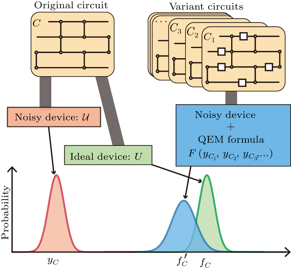

</mo><mo>,</mo><mn>0</mn><mo>,</mo><mi>sin</mi><mo stretchy="false">(</mo><mstyle displaystyle="true"><mfrac><mi>π</mi><mn>8</mn></mfrac></mstyle><mo stretchy="false">)</mo></mrow><mo>)</mo></mrow></mrow></math><inline-graphic xmlns:xlink="http://www.w3.org/1999/xlink" xlink:href="cpb_31_9_090306_ieqn76.gif"></inline-graphic></inline-formula></span>, the sampling overhead is <span class="formulaText"><inline-formula><tex-math></tex-math><math xmlns:mml="http://www.w3.org/1998/Math/MathML"><mrow><mi>γ</mi><mo>=</mo><mstyle displaystyle="true"><mfrac><mrow><mn>1</mn><mo>+</mo><mo stretchy="false">(</mo><msqrt><mn>2</mn></msqrt><mo>−</mo><mn>1</mn><mo stretchy="false">)</mo><mi>ϵ</mi></mrow><mrow><mn>1</mn><mo>−</mo><mn>2</mn><mi>ϵ</mi></mrow></mfrac></mstyle></mrow></math><inline-graphic xmlns:xlink="http://www.w3.org/1999/xlink" xlink:href="cpb_31_9_090306_ieqn77.gif"></inline-graphic></inline-formula></span> with the universal basis set, while the optimal overhead is <i>γ</i><sub>opt</sub> = 1/(1 – 2<i>ϵ</i>) with the basis <span class="formulaText"><inline-formula><tex-math></tex-math><math xmlns:mml="http://www.w3.org/1998/Math/MathML"><mrow><mo>{</mo><mo stretchy="false">[</mo><mi mathvariant="double-struck">I</mi><mo stretchy="false">]</mo><mo>,</mo><mi>exp</mi><mo stretchy="false">(</mo><mi mathvariant="normal">i</mi><mover accent="true"><mi>n</mi><mo>^</mo></mover><mo>⋅</mo><mover accent="true"><mi>σ</mi><mo>^</mo></mover><mi>π</mi><mo>/</mo><mi>n</mi><mo stretchy="false">)</mo><mo>}</mo></mrow></math><inline-graphic xmlns:xlink="http://www.w3.org/1999/xlink" xlink:href="cpb_31_9_090306_ieqn78.gif"></inline-graphic></inline-formula></span><span class="formulaNumber">.</span> Indeed we can achieve the optimal overhead if we use a flexible decomposition set. One method to find the optimal decomposition set is by the method of constraint optimization.<sup>[<a href="javascript:;" onmouseover="piaofu(this,) 14,48,49] Realistic quantum noise is complete-positive and trace-preserving (CPTP). As given in Ref. [49], the inverse of a CPTP map is Hermitian-preserving and trace-preserving (HPTP), and there exists the following decomposition:
, we can employ the following constraint optimization to determine the optimal resource cost:<disp-formula id="cpb_31_9_090306eqn24"><label>24</label><tex-math></tex-math><math xmlns:mml="http://www.w3.org/1998/Math/MathML"><mrow><mtable columnalign="left"><mtr columnalign="left"><mtd columnalign="left"><mrow><msub><mi>γ</mi><mrow><mi mathvariant="normal">opt</mi></mrow></msub></mrow></mtd><mtd columnalign="left"><mrow><mo>=</mo><mi mathvariant="normal">min</mi><mo stretchy="false">(</mo><msub><mi>λ</mi><mn>1</mn></msub><mo>+</mo><msub><mi>λ</mi><mn>2</mn></msub><mo stretchy="false">)</mo></mrow></mtd></mtr></mtable></mrow></math><graphic xmlns:xlink="http://www.w3.org/1999/xlink" xlink:href="cpb_31_9_090306_eqn24.gif"></graphic></disp-formula><disp-formula id="cpb_31_9_090306eqn25"><label>25</label><tex-math></tex-math><math xmlns:mml="http://www.w3.org/1998/Math/MathML"><mrow><mtable columnalign="left"><mtr columnalign="left"><mtd columnalign="left"><mrow><mi mathvariant="normal">subjected</mi><mspace width="0.25em)
</mo><mo>=</mo><msub><mrow><mi mathvariant="normal">Tr</mi></mrow><mi>B</mi></msub><mo stretchy="false">(</mo><msub><mi>J</mi><mrow><msub><mi mathvariant="script">C</mi><mn>2</mn></msub></mrow></msub><mo stretchy="false">)</mo><mo>=</mo><msub><mi mathvariant="double-struck">I</mi><mi>A</mi></msub><mo>,</mo></mrow></math><graphic xmlns:xlink="http://www.w3.org/1999/xlink" xlink:href="cpb_31_9_090306_eqn26.gif"></graphic></disp-formula><disp-formula id="cpb_31_9_090306eqn27"><label>27</label><tex-math></tex-math><math xmlns:mml="http://www.w3.org/1998/Math/MathML"><mrow><msub><mi>J</mi><mrow><msub><mi mathvariant="script">C</mi><mn>1</mn></msub></mrow></msub><mo>≥</mo><mn>1</mn><mo>,</mo><mspace width="0.25em)