Ionic liquid gating control of planar Hall effect in Ni80Fe20/HfO2 heterostructures
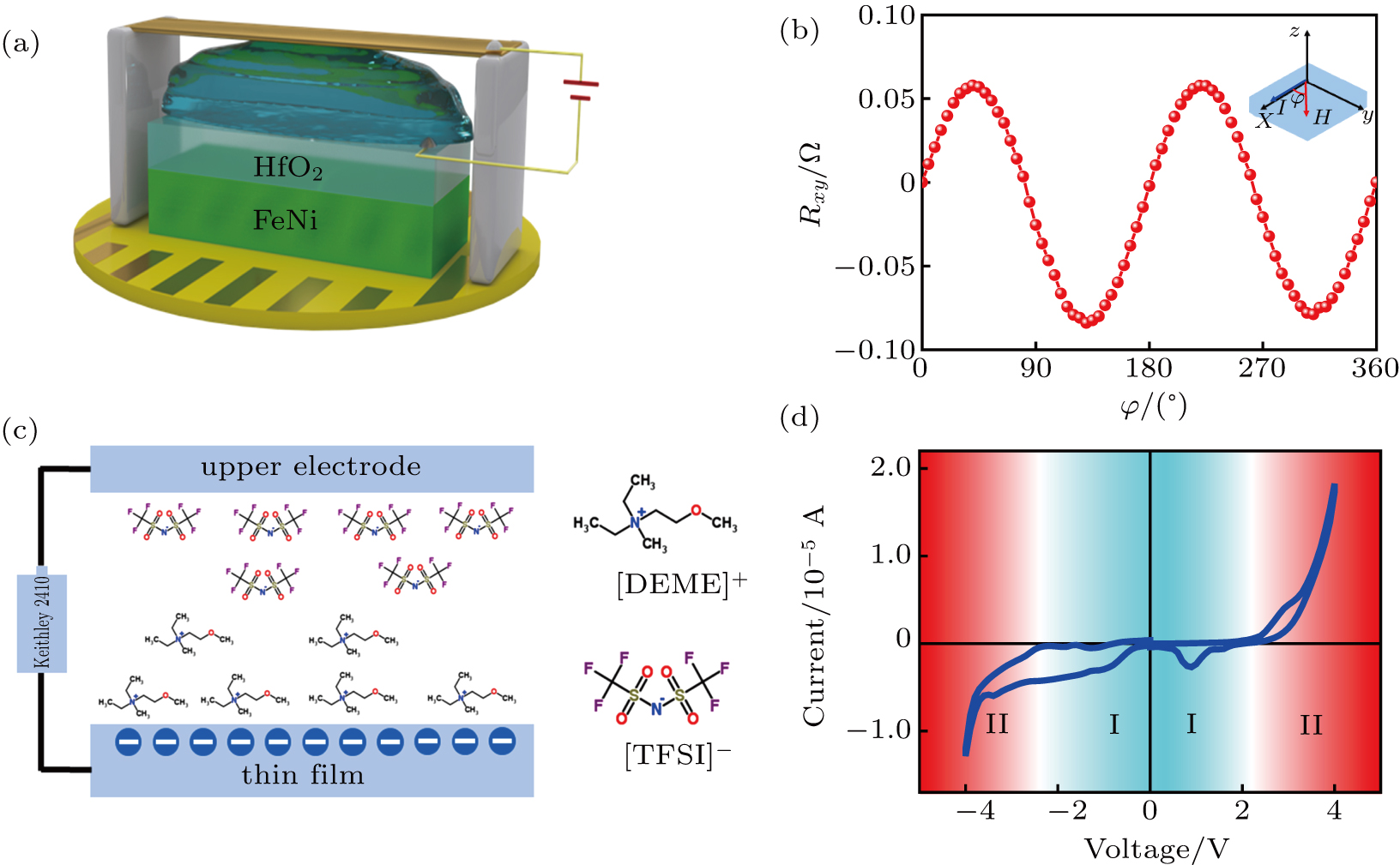
(a) A schematic diagram of the transport test after the addition of the ionic liquid. (b) The measured planar Hall effect (PHE) curve at a magnetic field of 1000 Oe. The inset shows the relationship between the current and external magnetic fields. (c) Schematic diagram of the directional movement of anions and cations after application of a voltage by a voltage source Keithley 2410. (d) The I–V curve representing the amount of charge accumulation at the interface at different gate voltages.
