† Corresponding author. E-mail:
Project supported by the National Natural Science Foundation of China (Grant No. 11902190), the Construction Project of Shanghai Key Laboratory of Molecular Imaging (Grant No. 18DZ2260400), and the Fund from the Shanghai Municipal Education Commission, China (Class II Plateau Disciplinary Construction Program of Medical Technology of SUMHS, 2018-2020).
Spatial filtering velocimetry (SFV) has the advantages of simple structure, good stability, and wide applications. However, the traditional linear CCD-based SFV method requires an accurate angle between the direction of linear CCD and the direction of moving object, so it is not suitable for measuring a complex flow field or two-dimensional speed in a granular media. In this paper, a new extension of spatial filtering method (SFM) based on high speed array CCD camera is proposed as simple and effective technique for measuring two-dimensional speed field of granular media. In particular, we analyzed the resolution and range of array CCD-based SFV so that the reader can clarify the application scene of this method. This method has a particular advantage for using orthogonal measurement to avoid the angle measurement, which were problematic when using linear CCD to measure the movement. Finally, the end-wall effects of the granular flow in rotating drum is studied with different experimental conditions by using this improved technique.
Granular materials are ubiquitous in the nature and important in various industries. The granular material exhibits a peculiar flow behavior that it can show both flow characteristics of the solid and the liquid depending on the conditions.[1] Therefore, research on granular flow has been a hot and difficult topic in the past few decades. Among a number of physical quantities that can characterize the motion features of the granular flow, speed is the most essential feature for characterizing the motion of granular flow. In particle’s speed measurement field, particle image velocimetry (PIV) and particle tracking velocimetry (PTV) are two of the most common used methods. They can measure both particle’s speed[2–5] and acceleration.[6–8] However, PTV requires a clear image of each particle, which means this method needs more stringent experimental conditions and equipment. Although PIV does not need a clear image with each particle, in order to obtain large signal-to-noise ratio (SNR) images, the experimental system requires very uniform illumination which is difficult to realize since the imaging and lighting system with the observed particles and accompanying scene have a complex interaction.[9–14]
Spatial filtering velocimetry (SFV) is another method that can measure granular flow speed. Compared with the mentioned methods above, the main advantages of this method are high resolution, non-contact, and strong environmental adaptability. It does not require a clear image of each particle. In the scenes where it is not easy to obtain a high SNR image, this method will be more suitable than PIV due to non-uniform illumination and other factors.[15] In the 1960s, Ator[16] first proposed the concept of spatial filtering method (SFM) and applied it to the measurement of the movement of particle motion in the air. Since then this method was used to measure the speed of rough surface fluid and solid–liquid two-phase flows.[17–20] With time and development of new spatial filtering methods, CCD cameras have gradually replaced traditional structural gratings. The CCD camera acts as a spatial filter and a photo-receiving device, making the speed measurement structure much simpler. Uddin et al.[21] used a linear CCD to simulate a traditional grating in a spatial filter system for the first time. Yang et al.[22,23] used a linear CCD to measure the speed of irregular particles in the rotating drum and showed that the method is suitable for granular flow measurements. One drawback of the linear CCD-based SFV for granular flow applications is the need to accurately measure the angle between the pixel array and the direction of motion in actual measurement, which limits granular flow applications as usually the angle cannot be accurately determined. On the other hand, granular flow is almost never one-dimensional as accessible by linear-based SFV so a strong need is to extend the technique to measure two-dimensional speed.
In recent years, with the emergence of more and more complex scenes, researchers proposed a new SFV method based on array CCD camera.[24] This is a great improvement in the field of SFV at the time. Array CCD-based SFV can measure the speed components in orthogonal direction, so the errors caused by angular measurement can be avoided. Therefore, array CCD can replace linear CCD as the main device of spatial filtering system especially in the context of granular material flow measurement. However, as far as we know, there is no detailed study about parameters such as system’ resolution and range, etc.
On the basis of the above description, this paper makes a further study on the array CCD-based SFV, especially study the sensitivity, range, and temporal-spatial resolution of the measurement system. In this measurement, we focused on the end-wall effects of granular flow in rotating drum[25] as important phenomena to be studied, since the previous paper[26] did not study the continuous state of the granular flow. Finally, the influences of different factors on the end-wall effects are presented and discussed.
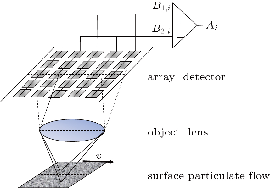
Spatial filter velocimetry is used to measure the speed by observing the optical image of the moving object through a set of parallel slits or transmission gratings. Figures

 | Fig. 1. Schematic diagram of (a) SFV measurement system and (b) spatial filtering signal generation process. |
Due to the complexity of structures, the difficulty of processing, and the fixed space period, the traditional SFV system with transmission grating and thermoelectric sensor structure has been gradually replaced by CCD/CMOS cameras. The use of CCD cameras greatly simplifies the system structure, and increases flexibility and stability. The traditional linear CCD which replaced the traditional grating in the early stage cannot meet the requirement of measurement for multi-directional speed, so the array CCD has become the main acquisition device in current SFV system[28,29] to study the end-wall effects in our simple rotating drum.
According to the analysis above, the most important problem of the spatial filtering velocimetry system is the spatial filtering effect produced by the grating. Let f (x,y) be the light intensity distribution and h (x,y) be the light intensity transmittance. Supposing the image moves with speed components vx and vy in directions x and y, respectively. The signal obtained by the photodetector can be expressed by the following formula:[30]


Array CCD is a photodetector composed of discrete pixels. By selecting a specific pixel unit, the traditional grating can be simulated by the array CCD as a spatial filter for measurement. The schematic diagram of the array CCD simulating the spatial filter in the horizontal direction is shown in Fig.
Each of the light-transmitting area and the light-shielding area constitutes a spatial period P, which is represented as an adjacent odd-numbered column and an even-numbered column on the image, and the number of spatial periods n can be obtained by dividing the total number of columns by the space period P. Speed Vy in the vertical direction of the object can be obtained in the same way. Finally, the actual moving speed, V, of the object can be calculated according to the vector summation formula.
According to the array CCD-based SFV principle and the actual measurement demand, the drum granular flow speed measuring system is constructed, as shown in Fig.
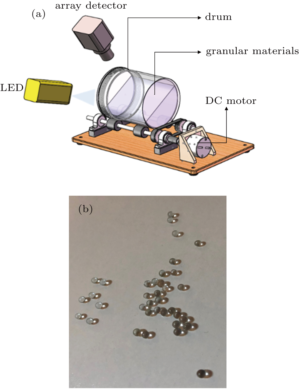 | Fig. 3. (a) Schematics of array CCD-based SFV measurement system applied to rotating drum. (b) Sample picture of 1-mm diameter glass beads. |
The rotating drums used in this article are all made of plexiglass and driven by a DC motor on a turntable. The diameter of the drum is 140 mm with 3 different drum lengths of 100 mm, 150 mm, 200 mm. The particles are all glass beads with a density of 2.7 g/cm3, and the selected sizes are 0.5 mm, 1 mm, and 2 mm. A sample of 1-mm diameter glass beads is shown in Fig.
In order to verify the effectiveness of the measurement system and evaluate the accuracy of the array CCD measurement system, first, the SFV measurement system was used to measure a uniform moving conveyor belt. Figure
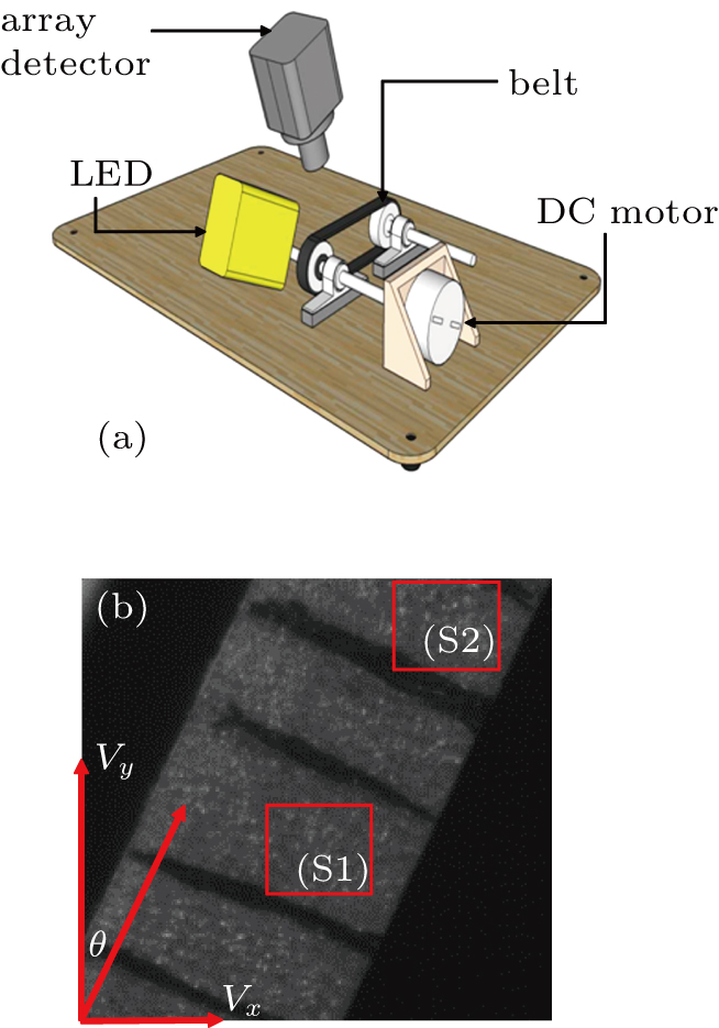 | Fig. 4. (a) Conveyor belt speed measurement system. (b) Example of original image collected by the array CCD used in analysis with two regions of interest (S1 and S2) outlined. |
After setting up the measuring system, the amplification M, which can be calculated according to the ratio of the actual length of the object to the number of pixels it occupies in the picture, should be determined first. The belt width is 104 μm, and the number of pixels (single pixel width is 7 μm) the belt occupies in the picture is 81, so the system amplification factor can be calculated as 0.0567. Measurement of granular flow does not require changing the device position and system parameters, so the magnification in the following experiment is the same. In order to verify that the array CCD-based SFV will not be affected by the placement angle, first we adjust the angle between the conveyor belt and the array CCD, and take the images at different angles for speed measurement; to verify the rationality of multi-point measurement scheme for segmentation of array CCD into multiple sub-filters, two regions S1 and S2 are selected from the original image as sub-filters for speed measurement.
The experiment set the conveyor speed V from 3 cm/s to 9 cm/s in 3-cm/s step value for a total of three speed values, besides, we set two different angles 30° and 45° for measurement. All of the following data are the average of ten experimental runs. Table
| Table 1. Multi-angle speed comparison results in region S1. . |
| Table 2. Multi-point measurement results for 30° angle between conveyor belt and array CCD. . |
Comparing the above data, it can be found that the array CCD-based SFV method is not affected by the placement angle, and the maximum error is less than 1.9%, which is lower than the linear CCD-based SFV method proposed by our team before (the maximum error is 2.46%).[22] Compared with the speeds in S1 and S2 regions, it can be found that the speed calculation results between the two regions are consistent. Array CCD can perform multi-point measurement on granular flow speed field which makes up for the deficiency of the linear CCD. Therefore, spatial filtering velocimetry measurement based on array CCD is feasible and superior to spatial filtering velocimetry measurement based on linear CCD.
If the object to be tested moves at a constant speed v and the camera frame rate is r, then the distance that the object actually moves during the time interval t between two adjacent frames is


The system resolution includes time resolution Rt and a spatial resolution Rs. Theoretically, Rt and Rs are only related to the CCD camera characteristics. The time resolution Rt = 1/f is determined by the camera frame rate f. Increasing the frame rate f, the time interval between the two frames becomes shorter and the continuity of the output signal gets better, then the surface speed of the granular flow will be more accurate. The maximum frame rate of the camera used in this experiment is 40600 frames per seconds (fps), so the minimum time resolution Rtmin is 1/40600 s. The spatial resolution Rs = n⋅ p is determined by the space period size p and the slit number n. Generally, at least two rows (columns) of pixels can form a spatial period. In order to obtain the speed information of the object to be tested, one spatial period is required at least. Therefore, the minimum spatial resolution of the system is the pixel width of the two rows (columns) of the CCD camera. The single pixel size of the CCD camera used in this experiment is 7 μm, considering the magnification of the experimental system, M, the minimum spatial resolution of the system is Rsmin = 14⋅ M in units of μm.
In the actual situation, considering the real-time demands of the measurement and the granular flow setup, we need to choose the optimal Rt and Rs. After measuring and comparing the same motion scene with different frame rates, it can be found that when the camera frame rate set at 1000 fps, the signal will possess a large signal to noise ratio (SNR) enabling confident determination the peak frequency f0. The increase of frame rate will lead to decrease in SNR introducing ambiguity in peak frequency determination which limits a real-time measurement. Therefore, the best time resolution is 0.001 s; when changing the space period to calculate the scene to be measured, we find that the output signal has the best periodicity when the space period is set to 100 μm–120 μm. When the spatial period p is constant, we will get a larger sensitive area when the analog slit number becomes large. The size of the sensitive area directly affects the filtering effect of the spatial filter, mainly in the amplitude and main peak bandwidth of the spatially filtered signal: the more the number of stripes is, the narrower the bandwidth of the main peak of the signal and the higher the resolution become. However, as n increases, the single measurement area gets larger, the measurable points in the whole area are reduced, the measurement accuracy is lowered. For the same position of the drum, we set the same space period size p and the different number of slits n. After multiple measurements and analysis, it can be found that the most suitable number of slits n is 10. Thus, the best spatial resolution is 1 mm.
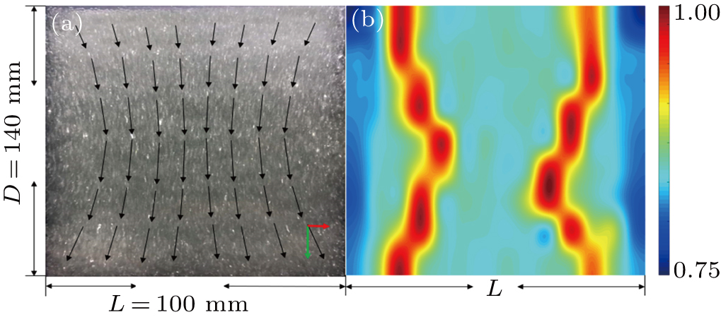
Figure
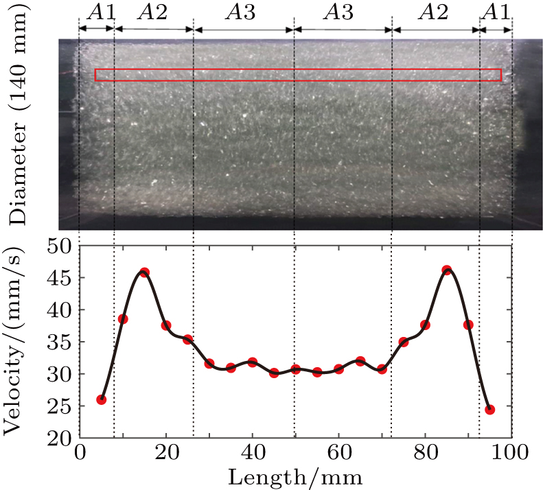
In order to study the axial flow variation of the drum particle, as shown in Fig.
The following part will specifically study the end-wall effects with different conditions. From the above speed distribution, it can also be found that the axial granular flow speed has symmetry in the axial direction, so all of the following results only show the speed distribution from the left side to the center axis of the drum. It should be noted that all the following works are carried out in the rolling state, since the end-wall effects in this state are more obvious.
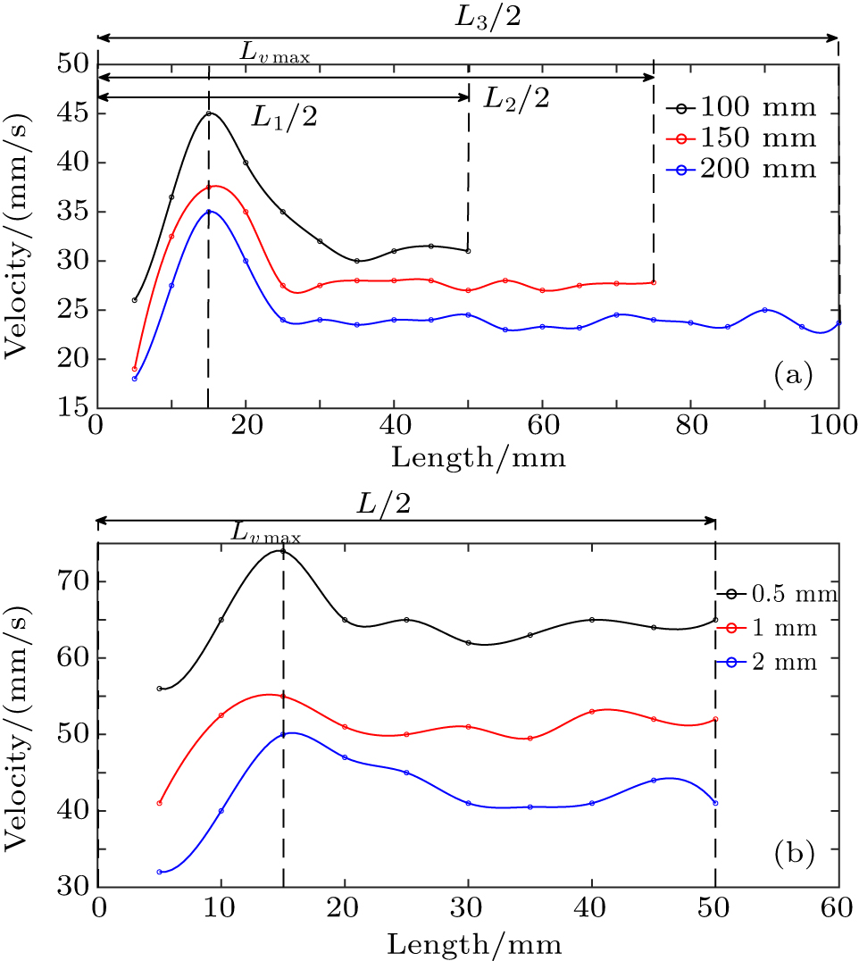
In order to investigate the influence of different drum lengths and particle sizes on the end-wall effects, we used different length drums and different size particles in experiments. Figure
Figure
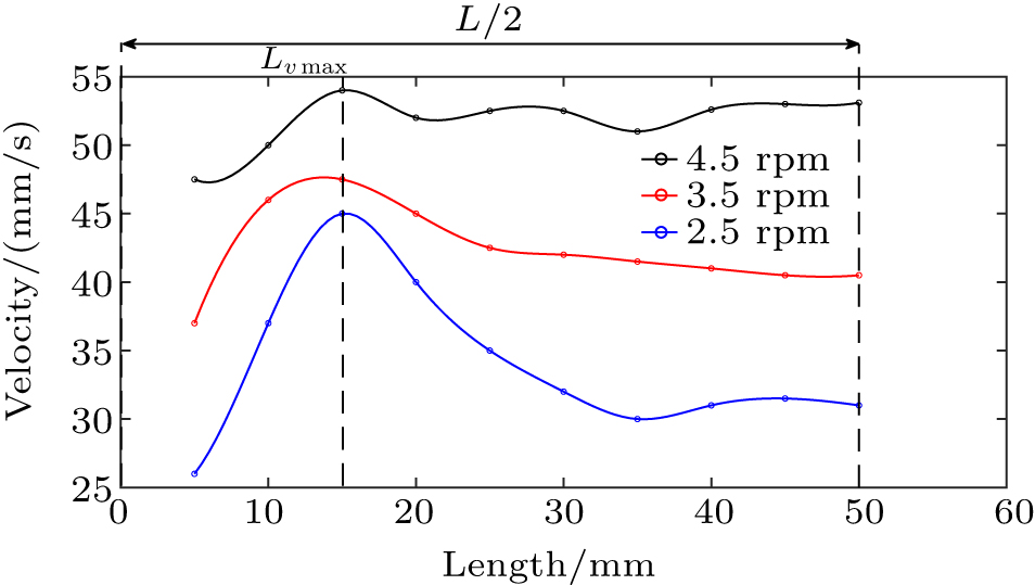
In this section the drum rotating speed is varied to study the effects of speed on the end-wall effects. As shown in Fig.
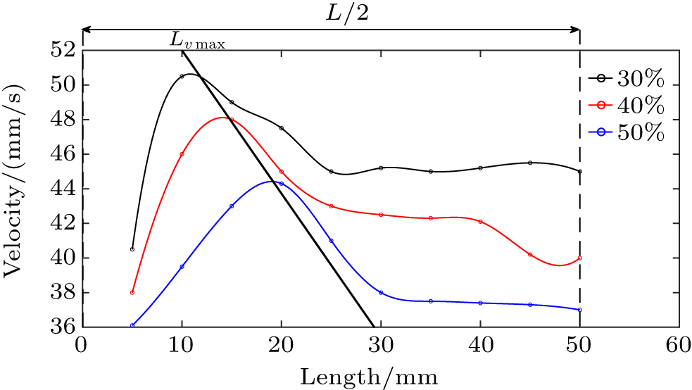
Considering the degree of filling, since the surface area of the flow layer in different filling degrees is different in the same drum, the best solution is to compare the central axial area of the surface of the particle stream. Experimentally, when the filling degree is too low, the obtained motion fluctuates greatly, so the filling degree was changed from 30% to 50%.
As shown in Fig.
In the study of the speed field of particles surface flow within rotating drum, the end-wall effects cannot be ignored. We combined the SFV method with an array CCD and proposed an improved method for granular flow measurement. This paper focused on the SFV system’s sensitivity, range, and temporal-spatial resolution. Compared with linear CCD, array CCD can not only obtain the entire surface flow field of the particles but also eliminate the angular error by vector summation. Therefore, this method can accurately measure the whole field speed profile of the drum, so the end-wall effects of the rotating drum flow can be analyzed. By analyzing different drum parameters separately, this article also achieved got the following conclusions:
End-wall effects of the drum occurs only in the end-wall regions at both ends, due to the friction of the end wall. The speed of the particles near the end wall is smaller than that of the particles away from the end wall. According to the law of conservation of momentum, a slow granular flow will compensate for the granular flow with a fast speed, which will result in an axial speed of the flow of particles. In addition, due to the effect of speed superposition, a peak speed occurs a little further from the end wall. To reduce the influence of end-wall effects, the method of increasing drum rotating speed and length can be adopted. When the drum at a high rotating speed, the peak speed becomes less obvious and the end-wall effects area is shrinking. The main reason is that when the rotating speed of the drum increases, the influence of the inertial force on the granular flow caused by the drum rotation will be much greater than that of the friction force caused by the end wall. Although changing the length of the drum and the particle size does not affect the position of the peak speed, as the drum gets longer, the steady speed area in the middle of the drum will get larger, therefore, more effective values can be obtained in one experiment.
| [1] | |
| [2] | |
| [3] | |
| [4] | |
| [5] | |
| [6] | |
| [7] | |
| [8] | |
| [9] | |
| [10] | |
| [11] | |
| [12] | |
| [13] | |
| [14] | |
| [15] | |
| [16] | |
| [17] | |
| [18] | |
| [19] | |
| [20] | |
| [21] | |
| [22] | |
| [23] | |
| [24] | |
| [25] | |
| [26] | |
| [27] | |
| [28] | |
| [29] | |
| [30] | |
| [31] | |
| [32] | |
| [33] | |
| [34] | |
| [35] | |
| [36] | |
| [37] |


