Tilt adjustment for a portable absolute atomic gravimeter
Xie Hong-Tai1, 2, 3, Chen Bin1, 2, 3, Long Jin-Bao1, 2, 3, Xue Chun4, Chen Luo-Kan1, 2, 3, Chen Shuai1, 2, 3, †
Hefei National Laboratory for Physical Sciences at the Microscale and Department of Modern Physics, University of Science and Technology of China, Hefei 230026, China
Shanghai Branch, CAS Center for Excellence in Quantum Information and Quantum Physics, University of Science and Technology of China, Shanghai 201315, China
Shanghai Research Center for Quantum Sciences, Shanghai 201315, China
Shanghai Division, QuantumCTek Co., Ltd., Shanghai 201315, China


† Corresponding author. E-mail: shuai@ustc.edu.cn

Project supported by the National Key R&D Program of China (Grant No. 2016YFA0301601), the National Natural Science Foundation of China (Grant No. 11674301), Anhui Initiative in Quantum Information Technologies, China (Grant No. AHY120000), and Shanghai Municipal Science and Technology Major Project, China (Grant No. 2019SHZDZX01).

Abstract

For an atomic gravimeter, the measured value of the Earth’s gravity acceleration g is the projection of the local gravity on the direction of Raman laser beams. To accurately measure the g, the Raman laser beams should be parallel to the g direction. We analyze the tilt effect of the Raman beams on g measurement and present a general method for the tilt adjustment. The systematic error caused by the tilt angle is evaluated as 0 (+0, –0.8) μGal (1μGal = 10 nm/s2) and the drift is also compensated in real time. Our method is especially suitable for the portable atomic gravimeter which focuses on the mobility and field applications.

1. Introduction

Measurement of the Earth’s gravity acceleration g is important for numerous scientific studies and applications, such as the new definition of kilogram,[1] geodesy, geophysics, resources exploration,[2] and autonomous navigation.[3] The best-performing gravimeters at present time include relative gravimeters[4,5] and falling corner cube gravimeters[68] based on optical interferometry. With these high performing instruments, researchers can measure g in a very high sensitivity and accuracy (up to μGal level). Cold atomic gravimeters based on matter wave interferometry have been rapidly developed since the 1990s[920] and have achieved extremely high sensitivity[21] and stability[22] that had advanced to the high performing falling corner cube gravimeters. The comparison of absolute gravimeters shows that the degree of equivalence and the uncertainty of atomic gravimeters also reach several μGal (1 μGal = 10 nm/s2)[23] and ready to be used in real applications.

Based on the two-photon Raman transition between two hyperfine levels of the atom ground state, a π/2–ππ/2 Raman pulse sequence splits, reflects, and recombines the atomic wave packet for the interferomety.[9] The phase shift due to the gravity is as follows:

where ΔΦ is the phase shift of the interferometer, keff is the effective wave vector of the Raman lasers and T is the interogation time between the Raman pulses. From Eq. (1), the measured value of g is the projection of g onto the keff direction. The accuracy is partly dependent on the tilt angles of the Raman lasers of the atom interferometer.[11]

Researchers have made considerable efforts to correct the systematic error caused by tilt, such as calibrating the direction of the incident beam with a liquid surface,[24] determining the orientation of the mirror with an electronic bubble level,[11] calibrating the directions of the Raman beams with a beam-splitter and a CCD camera,[25] and adjusting the reflected beam overlap the incident beam with a photo-diode.[26] These methods are suitable for atomic gravimeters in labs or fixed stations, but too complicated for the portable atomic gravimeters. There are also some methods that meet the portable demand. For example, use a corner cube mirror to make the reflected beam overlap the incident beam,[27] but may cause worse wavefront aberrations;[2830] and adjust the directions of the incident beam and reflected beam for parabola fitting respectively,[31] but the direction of the reflected beam is not independent of incident beam, which induces a cross term and makes the adjustment invalid.

In this paper, we provide a common approach for the tilt adjustment of the Raman laser beams in a portable absolute atomic gravimeter. By applying this approach, the systematic error of our portable atomic gravimeter USTC-AG02 according to the tilt is effectively eliminated, becomes 0 (+0, -0.8) μGal considering the uncertainty. Also, with continuous tilt monitoring, the compensation for the measured g value is applied to enhance the long term accuracy. This approach especially fit for the gravimeter adjustment in the field applications.

2. The atomic gravimeter

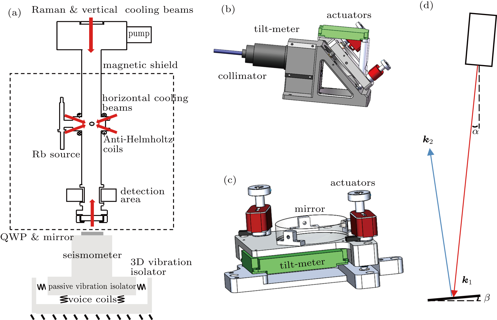
The absolute atomic gravimeter USTC-AG02 is based on the Mach–Zehnder type atom interferometer. The schematic diagram of the gravimeter’s sensor is shown in Fig. 1(a). The Raman lasers and the vertical cooling laser are combined and injected into the vacuum chamber from the top. They are retro-reflected by a vibration-isolated mirror to form the counter-propagating scheme. The additional four cooling beams were horizontally shine into the vacuum in the magneto-optical trap (MOT) area. In the detection area, the probe lasers are applied to excite the falling atoms to generate the resonant florescence for F = 2 and F = 1, respectively. For each g-measurement circle, about 108 cold 87Rb atoms were captured by the MOT and further cooled down to 5 μK by the polarization-gradient cooling in 100 ms. For initial state preparation, a series of Raman pulses are applied to prepare the atoms in the |F = 1, mF = 0〉 initial state, with the vertical temperature of 300 nK and remaining atoms of around 106. During the free-falling, the interferometry was realized by the π/2–ππ/2 Raman pulse sequence with the interogation time of T = 90 ms. Finally, the florescence of the atoms are collected in the detection zone to get the population in both the |2,0〉 and |1,0〉 states. The probability in the F = 2 state was normalized as[11]

where A is the contrast of the interferometry signal and the ΔΦ is the phase shift induced by the gravity as shown in Eq. (1).

Fig. 1. (a) Schematic diagram of the USTC-AG02 sensor. It includes an atom interferometer, a magnetic shield, and a 3D vibration isolator. (b) Illustration of the Raman beam collimator on top of the vacuum chamber. (c) Illustration of the retro-reflector on the bottom of the vacuum chamber. (d) The Raman beam comprises of two counter-propagation beams, with wave vectors of k1 and k2. Here α is the tilting angle of k1, and β is the tilting angle of the retro-reflection mirror. The angle between k2 and g is π – (2βα).
Fig. 2. The measured g-value varying the tilt angles in the third round adjustment. The black squares with error bars correspond to the experimental data, and the red curves are the parabolic fits. The extreme points are αx0 = –8553.4 μrad, αy0 = –1193.3 μrad, βx0 = 4459.0 μrad, and βy0 = –1706.0 μrad.

The Raman beams entered the vacuum chamber through a fiber collimator with a 45° mirror (Fig. 1(b)) and were reflected back by a vibration isolated 0° reflective mirror (Fig. 1(c)). The tilting angle of the downward and upward beams could be precisely tuned by the fine-adjustment screws with electronic actuators. The two biaxial tilt meters that recorded the tilting angles were mounted on the fiber collimator and 0° reflective mirror, respectively. The tilt meter on top recorded the tilting angles αx and αy of the downward Raman laser, and the bottom one recorded the tilting angles βx and βy of the reflective mirror in x and y directions, respectively. The four angle readings (αx, αy, βx, and βy) were set to be independently controlled by the four actuators. In order to get rid of the cross-talk during the adjustment, the axes of the actuators and the correspond tilt meter are all aligned parallel to the framework of gravimeter, with the mounting error less than 0.5°.

3. Method: Tilt adjustment

The direction analysis of the effective wave-vector keff is shown in Fig. 1(d). Consider about the tilting angle, the phase shift of the gravimeter is given by[25]

Because |k1|≈ |k2|≈ |keff|/2 and α and β are small angles, we have

The residue phase shift which courses the systematic error induced by tilting is expressed as follows:

Since α and β are small, they can be expressed as α = (αx,αy), and β = (βx,βy),[31] and the deviation of g-value can be expressed as

As the four angles can be controlled by the four actuators independently, we can tune one while maintaining the other three fixed with monitoring the measured g value. For each round, we tune the four angles one by one in serial and record the measured g-value accordingly. Thus, we can get four sets of g-angle curves and make the parabolic fit to obtain the extreme point for each. When varying αx and keep the other three fixed, equation (6) could be transformed to

where C1 is a constant. The extreme point of Eq. (7) is αx = βx. In the following, when varying βx, equation (6) turns to be

where C2 is another constant. The extreme point of Eq. (8) is βx = αx/2. Similarly, for the varying of αy and βy, the extreme points are βy and αy/2, respectively.

From the analysis we know that only the single adjustment round cannot correct the Raman beams along vertical direction precisely and cannot eliminate the tilting induced systematic error. After applying many adjustment rounds and setting the angles to the corresponding extreme points for each round, the four tilt angles decrease to a convergence value, as seen in Table 1. In this way, we can finally make keff parallel with g.

Table 1.

The residues of the four tilt angles, which vary according to the adjustment rounds.

.

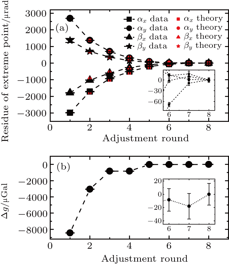
After the tilting angles are set to the extreme points at the end of each round, we start to perform the next adjustment round. The extreme points with varying adjustment rounds is shown in Fig. 3(a). We can see that in the first 6 adjustment rounds, the extreme points are monotonically approaching a convergence value, and fit with the theoretical results well. From round 6 to round 8, the extreme points keep unchanged with only small fluctuations. This indicates that the limits of the tilt-meter resolution are reached. The uncertainties (standard deviations) of the tilt angles after the adjustment are as follows:
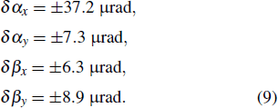
Converting the uncertainty of the tilt angle to the uncertainty of the g value with Eq. (6), we obtained an uncertainty of g value due to the tilt of the Raman beams which is δ gtilt = (+0,–0.8) μGal.

Fig. 3. (a) The residues of extreme points of the four tilt angles due to the adjustment rounds. The residues were obtained by subtracting the offset values (the extreme points of round 8) from the extreme points of each round. The black symbols and bars indicate the experimental data, and the red symbols indicate the theoretical values (see Table 1). The inset figure shows an enlarged view of the last three adjustment rounds. (b) The measured g-values due to the adjustment rounds. The g-values have been subtracted by the Earth tide and the g-value of round 8. The inset figure shows an enlarged view of the last three adjustment rounds.

We have measured g at the beginning of each adjustment round, as shown in Fig. 3(b). It is clear that the measured g-values are increasing with the adjustment round, which means that the real tilt of the Raman lasers becomes smaller and smaller. After 5 rounds, the g-value converges.

3.1. Tilt drift and realtime measurement

During the continuous measurement of the gravity acceleration over long time, we have observed the drifts of the tilting angles due to the relaxing of the mechanical structure of the gravimeter, which also affects the measurement results. The drifts of the four tilting angles are continuously monitored by the tilt meters. Figure 4(a) presents the drifts of the tilting angles over 36 hours. We can find that αx and αy are quite stable but βx and βy have a nearly linear drift. The calculated drift of the g measurement is shown in Fig. 4(b). It has a nearly linear drift in the first 30 hours with the rate of 0.142 μGal/h.

Fig. 4. Variations over time of the four tilt angles. (a) The observed drifts of four angles αx, αy, βx and βy. (b) The calculated drift of g-value corresponding to the drifts of the tilting angles.

The continuous measurement of g in our laboratory starts on December 12, 2018. We take the data for the first 36 hours, as shown in Fig. 5(a). By subtracting the measurement data with the calculated tide fluctuation with solid-tide model, the residue (Fig. 5(a) lower part) is obtained. The Allan deviation of the g measurement is shown in Fig. 5(b) (red curve). The sensitivity of our gravimeter is 5.5 μGal @ 300 s, correspond to about . We subtract the calculated drift of g (Fig. 4(b)) from the measurement value to calculate the Allan deviations (Fig. 5(b) (blue curve)). The comparison (Table 2) shows that the stability of our atomic gravimeter is not affected much by the drifting of the tilting angle.

Fig. 5. Continuous g measurement on December 12, 2018. (a) The black points indicate the measured data of g, each datum is an average of g measurement over atom falling of 900 times (approximately 298 s). The red line is the calculation from the Earth tide model. The residue shows the difference between the measured g and the tide model. (b) Allan deviation of the g measurement with and without tilt drift correction.
Table 2.

Comparison between the performances without and with tilt compensation (TC).

.
4. Conclusion

We have found a practical approach to precisely adjust the Raman laser beams in an absolute atomic gravimeter. By applying the multi-stage adjustment, the measured g gradually converges to an extreme maximum value, which tells us that the pointing of the Raman lasers is parallel to g direction. For our gravimeter USTC-AG02, the systematic error due to the tilting has been well eliminated and becomes 0 (+0, –0.8) μGal considering the uncertainty. The long-term drift of the tilting angle has also been monitored and the compensation was applied during the continuous measurement of g. Our method is especially suitable for the compact and portable gravimeters used for the mobile gravity measurements and observations.

Reference
[1] de N Darrigol O Schlaudt O 2019 The Reform of the International System of Units (SI) London Routledge 131
[2] Marson I Faller J E 1986 J. Phys. E: Sci. Instrum. 19 22
[3] Rice H Kelmenson S Mendelsohn L 2004 Proceedings of the IEEE Position Location and Navigation Symposium April 26–29, 2004 Monterey, USA 618 624 10.1109/PLANS.2004.1309051
[4] Prothero W A Goodkind J M 1968 Rev. Sci. Instrum. 39 1257
[5] Riccardi U Rosat S Hinderer J 2011 Metrologia 48 28
[6] Okubo S Yoshida S Sato T Tamura Y Imanishi Y 1997 Geophys. Res. Lett. 24 489
[7] Liard J Gagnon C 2002 Metrologia 39 477
[8] Li C J Xu J Y Feng J Y Su D W Wu S Q 2015 Proc. Volume 9446 Ninth International Symposium on Precision Engineering Measurement and Instrumentation March 6, 2015 Changsha, China 10.1117/12.2083901
[9] Kasevich M Chu S 1991 Phys. Rev. Lett. 67 181
[10] Peters A Chung K Y Chu S 1999 Nature 400 849
[11] Peters A Chung K Y Chu S 2001 Metrologia 38 25
[12] Gouet J L Mehlstaubler T Kim J Merlet S Clairon A Landragin A Santos F P D 2008 Appl. Phys. 92 133
[13] Zhou L Xiong Z Y Yang W Tang B Peng W C Wang Y B Xu P Wang J Zhan M S 2019 Chin. Phys. 28 013701
[14] Wang J 2015 Chin. Phys. 24 053702
[15] Wang Q Y Wang Z Y Fu Z J Lin Q 2016 Chin. Phys. 25 123701
[16] Abend S Gebbe M Gersemann M Ahlers H Muntinga H Giese E Gaaloul N Schubert C Lammerzahl C Ertmer W Schleich W P Rasel E M 2016 Phys. Rev. Lett. 117 203003
[17] Cheng Y Tan Y J Zhou M K Duan X C Shao C G Hu Z K 2018 Chin. Phys. 27 030303
[18] Huang P W Tang B Chen X Zhong J Q Xiong Z Y Zhou L Wang J Zhan M S 2019 Metrologia 56 045012
[19] Wu X Pagel Z Malek B S Nguyen T H Zi F Scheirer D S Muller H 2019 Sci. Adv. 5 eaax0800
[20] Wang S K Zhao Y Zhuang W Li T C Wu S Q Feng J Y Li C J 2018 Metrologia 55 360
[21] Hu Z K Sun B L Duan X C Zhou M K Chen L L Zhan S Zhang Q Z Luo J 2013 Phys. Rev. 88 043610
[22] Freier C Hauth M Schkolnik V Leykauf B Schilling M Wziontek H Scherneck H G Muller J Peters A 2016 J. Phys.: Conf. Ser. 723 012050
[23] Wu S Feng J Li C Su D Wang Q Hu R Hu L Xu J Ji W Ullrich C et al. 2020 Metrologia 57 07002
[24] Altin P A Johnsson M T Negnevitsky V Dennis G R Anderson R P Debs J E Szigeti S S Hardman K S Bennetts S Mcdonald G D Turner L D Close J D Robins N P 2013 New J. Phys. 15 023009
[25] Senger A A mobile atom interferometer for high-precision measurements of local gravity PhD Dissertation Berlin Humboldt University 54 55
[26] Hauth M Freier C Schkolnik V Senger A Schmidt M Peters A 2013 Appl. Phys. 113 49
[27] Menoret V Vermeulen P Moigne N L Bonvalot S Bouyer P Landragin A Desruelle B 2018 Sci. Rep. 8 12300
[28] Zhou M K Luo Q Chen L L Duan X C Hu Z K 2016 Phys. Rev. 93 043610
[29] Trimeche A Langlois M Merlet S Santos F P D 2017 Phys. Rev. Appl. 7 034016
[30] Louchet-Chauvet A Farah T Bodart Q Clairon A Landragin A Merlet S Santos F P D 2011 New J. Phys. 13 065025
[31] Wu B Cheng B Fu Z J Zhu D Zhou Y Weng K X Wang X L Lin Q 2018 Acta. Phys. Sin. 67 190302 in Chinese