


Frequency-dependent reflection of elastic wave from thin bed in porous media
Cite this Article
Li Hong-Xing, Tao Chun-Hui, Liu Cai, Huang Guang-Nan, Yao Zhen-An. Frequency-dependent reflection of elastic wave from thin bed in porous media. Chinese Physics B, 2020, 29(6): 064301 
Permissions
Frequency-dependent reflection of elastic wave from thin bed in porous media
† Corresponding author. E-mail:
Project supported by the National Natural Science Foundation of China (Grant Nos. 41764006, 41364004, and 41504095), the Chinese Study Abroad Fund (Grant No. 201508360117), the National Key Research and Development Program of China (Grant No. 2018YFC0309901), and the COMRA Major Project, China (Grant No. DY135-S1-01-01).
Abstract
The reflection of elastic wave from thin bed in porous media is important for oil and gas reservoir seismic exploration. The equations for calculating frequency-dependent reflection amplitude versus incident angle (FDAVA) from thin bed in porous media are obtained based on porous media theory. Some conclusions are obtained from numerical analysis, specifically, slow compression wave may be ignored when considering boundary conditions in most situations; the dispersion of reflection from thin bed is much higher than that from thick layer and is periodic in frequency domain, which is affected by the thickness of thin bed, velocity, and incident angle; the reflection amplitude envelope in frequency domain decays exponentially, which is affected by the thickness of thin bed, attenuation, and incident angle; the reflection amplitude increases with thickness of thin bed increasing, and then it decreases when the thickness reaches to a quarter of wavelength.
1. Introduction
The reflection seismic survey is the most important method in the field of oil and gas reservoir exploration. The amplitude of seismic reflection wave carries the information about underground media. The reflection amplitude versus incident angle (AVA) can be used to predict hydrocarbon. The AVA from thin bed (including interbed) is one of the difficult points for reservoir prospection and prediction. The reflection from thin bed, calculated by Zeoppritz equation which is based on single phase elastic medium theory, was extensively studied.[1–7] But the oil and gas reservoir is typical of porous media. The theory of wave propagation in porous media has been adopted in the field of soil, ocean sediment, and oil–gas reservoir, and so on.[8–25] There are fast compressional wave (FP wave), slow compressional wave (SP wave) and conversed shear wave (CS wave) in porous media and the reflection at the interface of thick layer in porous media have been extensively studied.[26–29] The fluid flows in pores will bring about wave attenuation and dispersion, and the wave dispersion in a seismic frequency range is proved in porous media.[30,31] Frequency-dependent reflection amplitude versus incident angle (FDAVA) was developed in recent ten years.[32–38] But there has been no paper to describe the frequency-dependent reflection from thin bed based on porous medium theory. In this paper, the Biot/Squirt model (BISQ) of porous medium is reviewed first. Then, the equations for calculating the frequency-dependent reflection coefficient from thin bed based on porous medium are obtained. The frequency-dependent reflection coefficients versus incident angle from thin sandstone reservoir and alternating thin bed of sandstone and mudstone are calculated and analyzed to answer the questions about the effect of wave dispersion, the thickness and structure of thin bed on wave reflection.
2. Biot/Squirt theory
The BISQ equations of wave propagation can be expressed as follows:[16]


3. FDAVA theory of thin bed in porous media


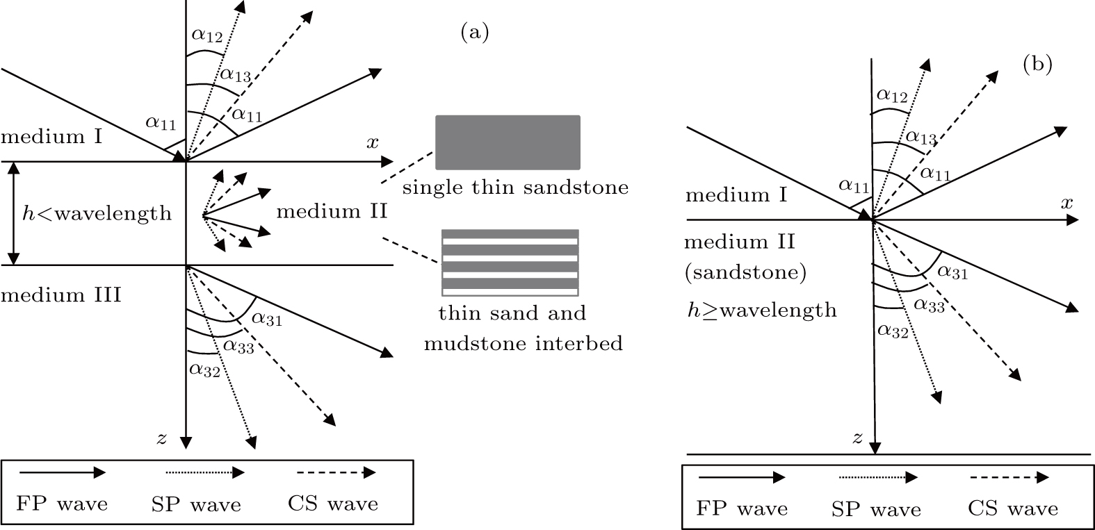
The geological thin reservoir model is shown in Fig.
 | Fig. 1. Reflection and transmission from (a) thin bed and (b) thick layer based on BISQ theory. |
The boundary conditions of reflection and transmission can be expressed by 


In the matter of thin interbed, the equation of AVA response can be expressed by Eq. (

The seismic common depth point gather (CDP) in time domain can be obtained from the following equation:

Because the wave number in those equations above is complex number and frequency dependent, so in the equations considered are the frequency-dependent velocity and attenuation. And the structure of thin interbed is considered in Eq. (
4. FDAVA analyses of thin bed
The parameters of mudstone (medium I and medium III) are set to be the same value (Table
 | Fig. 2. Velocity and attenuation of FP wave versus frequency in sandstone. |
| Table 1. Parameters of model based on BISQ model. . |
We use biconjugate gradient-stabilized method to solve linear equations (Eq. (
 | Fig. 3. FDAVA from (a) thick layer and (b) thin bed. |
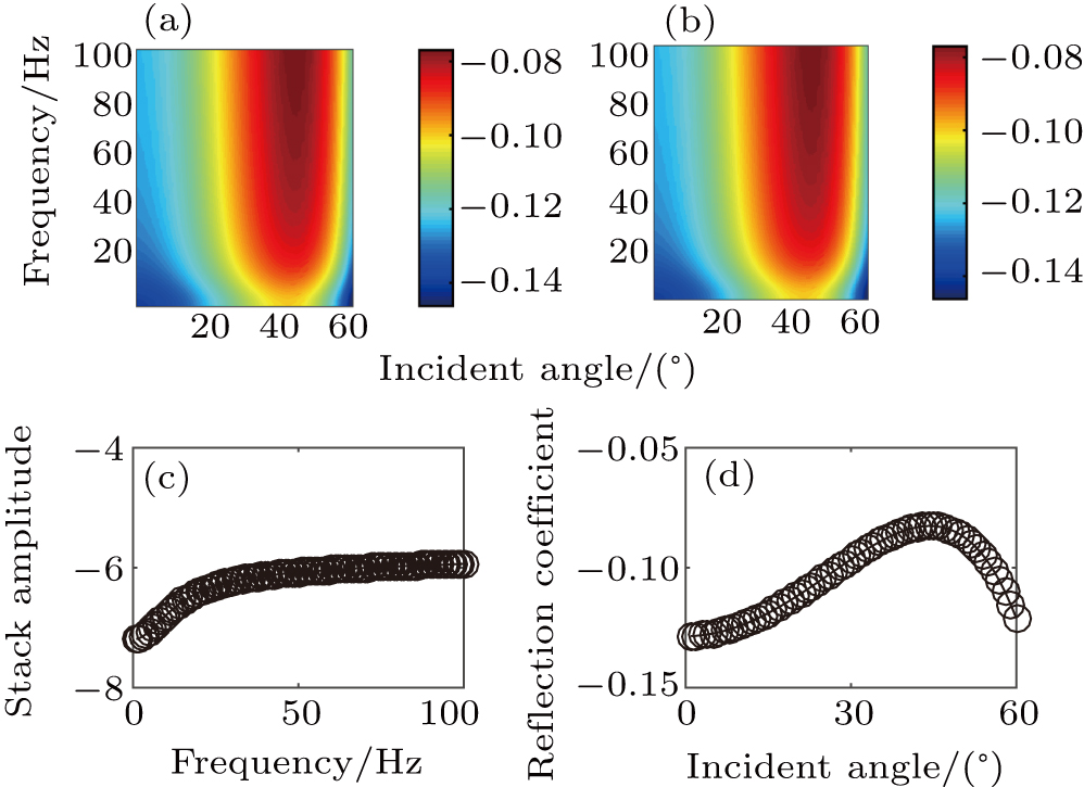
 | Fig. 4. Stack reflection amplitude versus frequency for (a) thick layer and (b) thin bed, and reflection coefficient versus incident angle for (c) thick layer and (d) thin bed. |
 | Fig. 5. Seismic wavelet in (a) time domain and (b) frequency domain. |
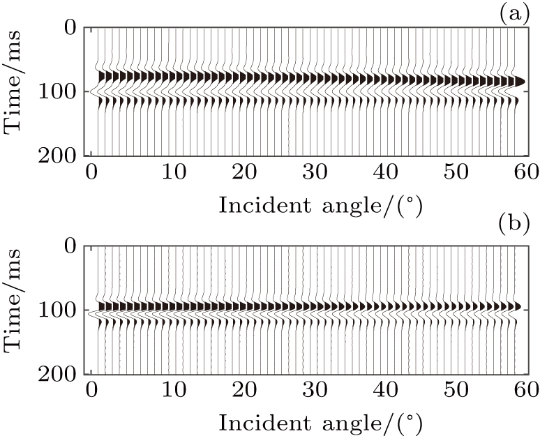 | Fig. 6. CDP gathers of (a) thick layer and (b) thin sandstone bed. |
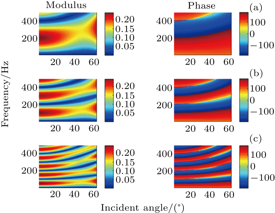
The modulus and phase of reflection coefficient show the periodic characteristic in frequency domain (Fig.
 | Fig. 7. Periodic FDAVA from thin bed with h = 5 m (a), 10 m (b), and 20 m (c), separately. |
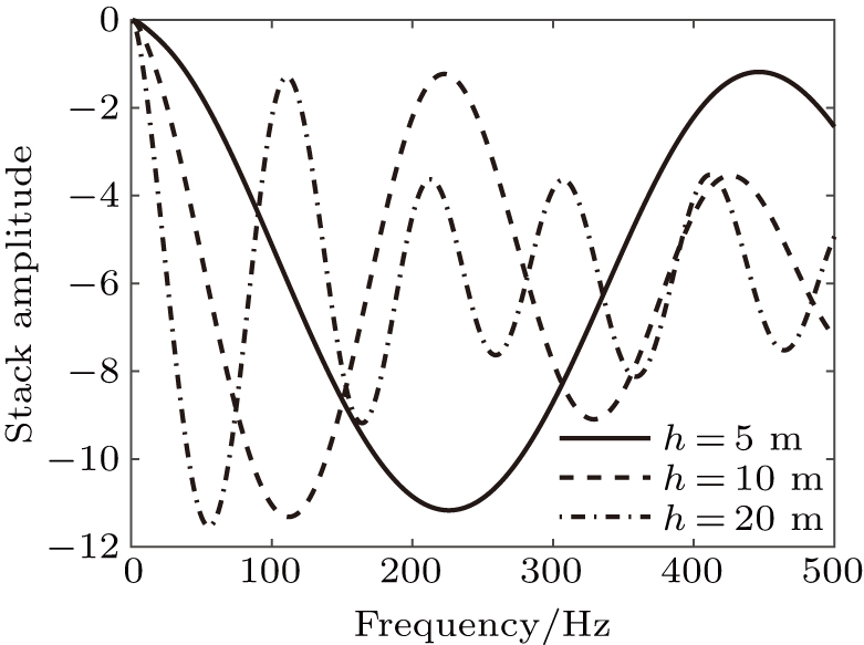
 | Fig. 8. Stack reflection amplitude of 0°–60° from thin bed with different thicknesses. |
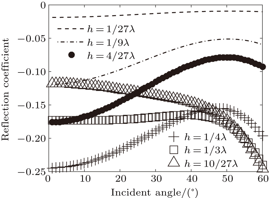
The reflection coefficient of 30-Hz wave increases with the thickness of thin bed increasing if the thickness is smaller than a quarter of wavelength. If the thickness is higher than a quarter of wavelength, the reflection coefficient decreases with thickness increasing when the incident angle is in a range of 0°∼ 40° (Fig.
 | Fig. 9. Reflection of 30-Hz wave from thin bed with different thicknesses. |
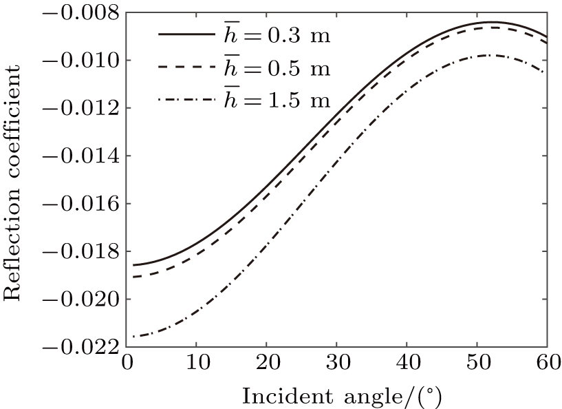
The general rules of FDAVA of thin interbed with fixed total thickness but different thicknesses of one layer (

 | Fig. 10. FDAVA from thin interbed (h = 7.5 m) with  |
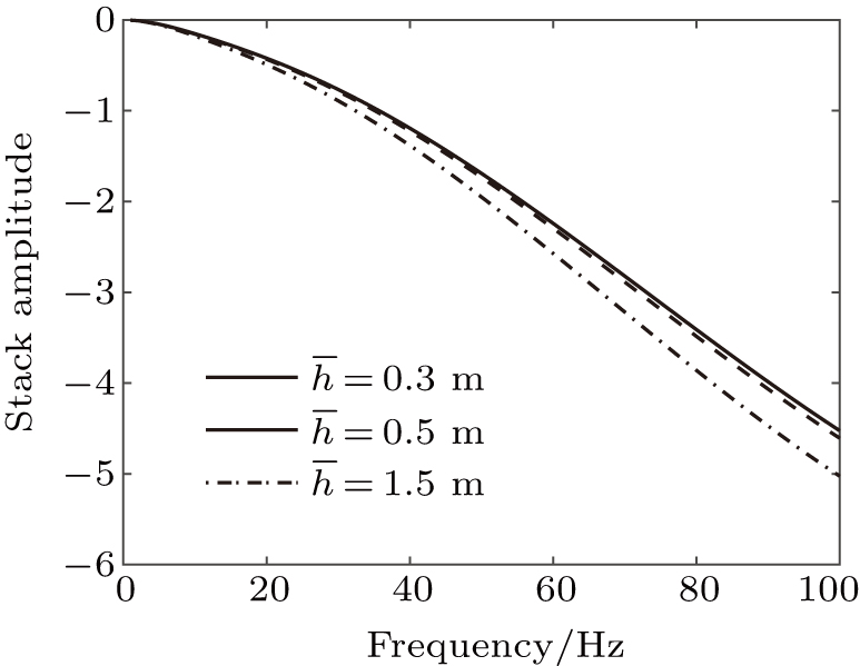 | Fig. 11. Stack reflection amplitude of 0°–60° from thin interbed for h = 7.5 m. |
 | Fig. 12. Reflection coefficient of 30-Hz wave from thin interbed versus incident angle for  |
There is SP wave in the porous media. The SP wave is difficult to receive in the seismic exploration work. That is caused by the high attenuation of SP wave. We compare the FDAVA of two types of thick layers: in the first type, the SP wave in the boundary condition is considered but in the second type the SP wave in the boundary condition is not considered. They are almost the same (Fig.
 | Fig. 13. FDAVA from thick layer with (a) and without (b) considering SP-wave, and (c) stack amplitude and (d) reflection coefficient of 30-Hz wave with (line) and without (circle) considering SP-wave. |
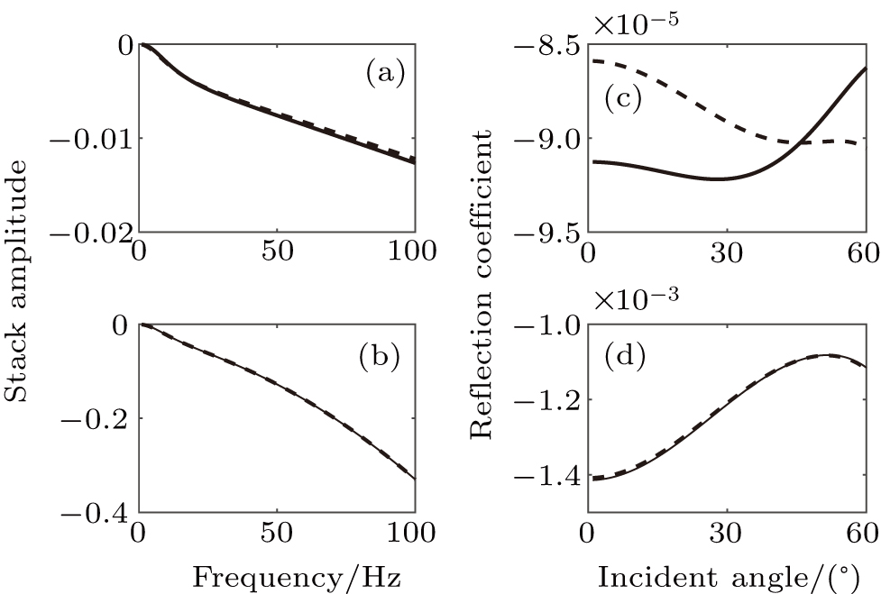 | Fig. 14. Stack reflection amplitude from thin bed (h = 0.1 m (a) and 1 m (b)), and reflection coefficient of 30 Hz from thin bed (h = 0.1 m (c) and 1 m (d) with (broken line) and without (solid line) considering SP wave in boundary conditions. |
5. Conclusions
The equations for calculating FDAVA from thin bed in porous media are obtained, with considering the effect of frequency-dependent velocity and attenuation, the thickness and structure of the thin bed. Through the numerical analysis, we obtain some conclusions below.
(i) The effect of SP wave on the FDAVA from thin bed in porous media can be ignored in most conditions except the fact that the thickness of thin bed is very small (cm level), which is likely to be caused by the high attenuation of SP wave, and the SP wave will decay in a short distance, which has been proved by the fact that it is difficult to detect slow P-wave in real survey.
(ii) The dispersion of FDAVA from the thin bed is much higher and more complicated than that from the thick layer, showing a periodic characteristic in frequency domain which is affected by the thickness of thin bed and incident angle. That is because the seismic wave dispersion of reservoir sandstone is much higher than that of surrounding mudstone. The envelope of stack reflection amplitude decays exponentially with frequency increasing, which is related to the thickness of thin bed, attenuation, and incident angle. So, it is possible to invert the thickness of thin layer by using the envelope of stack reflection amplitude changing with frequency. The stack reflection amplitude of FDAVA from the thick layer shows low frequency “bright spot”, but the stack reflection amplitude of FDAVA from the thin bed increases with frequency increasing. This phenomenon can be used for thin reservoir to be identified.
(iii) The reflection coefficient increases with the thickness of the thin bed increasing if the thickness is smaller than a quarter of wavelength and then decreases when the thickness is higher than a quarter of wavelength. The general rules of FDAVA obtained from thin interbeds whose total thickness is the same but each layer thickness may be changed, are basically consistent with each other. This is because in the example in this paper, although the thickness of the single layer in the thin interbed is different, the ratio between the sand and mudstone is the same because they are alternately distributed with the same thickness.
Reference
| [1] | |
| [2] | |
| [3] | |
| [4] | |
| [5] | |
| [6] | |
| [7] | |
| [8] | |
| [9] | |
| [10] | |
| [11] | |
| [12] | |
| [13] | |
| [14] | |
| [15] | |
| [16] | |
| [17] | |
| [18] | |
| [19] | |
| [20] | |
| [21] | |
| [22] | |
| [23] | |
| [24] | |
| [25] | |
| [26] | |
| [27] | |
| [28] | |
| [29] | |
| [30] | |
| [31] | |
| [32] | |
| [33] | |
| [34] | |
| [35] | |
| [36] | |
| [37] | |
| [38] | |
| [39] |