Experimental and computational study of visible light-induced photocatalytic ability of nitrogen ions-implanted TiO2 nanotubes
Zhang Ruijing1, Liu Xiaoli1, Hou Xinggang1, †, Liao Bin2, ‡
College of Physics and Materials Science, Tianjin Normal University, Tianjin 300387, China
Key Laboratory of Beam Technology and Material Modification of Ministry of Education, College of Nuclear Science and Technology, Beijing Normal University, Beijing 100875, China


† Corresponding author. E-mail: hou226@tjnu.edu.cn liaobingz@bnu.edu.cn

Project supported by the National Natural Science Foundation for Joint Fund Key Project of China (Grant No. U1865206), the National Science and Technology Major Project of China (Grant No. 2017-VII-0012-0107), the National Defense Science and Technology Key Laboratory Fund of China (Grant No. 614220207011802), and the Key Area Research and Development Program of Guangdong Province, China (Grant No. 2019B090909002).

Abstract

Nitrogen-doped TiO2 nanotubes (TNTs) were prepared by ion implantation and anodic oxidation. The prepared samples were applied in photocatalytic (PC) oxidation of methyl blue, rhodamine B, and bisphenol A under light irradiation. To explore the influence of doped ions on the band and electronic structure of TiO2, computer simulations were performed using the VASP code implementing spin-polarized density functional theory (DFT). Both substitutional and interstitial nitrogen atoms were considered. The experimental and computational results propose that the electronic structure of TiO2 was modified because of the emergence of impurity states in the band gap by introducing nitrogen into the lattice, leading to the absorption of visible light. The synergy effects of tubular structures and doped nitrogen ions were responsible for highly efficient and stable PC activities induced by visible and ultraviolet (UV) light.

1. Introduction

Access to clean drinking water was recognized as a human right according to UN regulations in 2010.[1] However, due to human activities, the water pollution arising from organic compounds is growing steadily around the world.[2] To solve this environmental challenge, the technology of photocatalytic (PC) remediation of wastewater has been attached a great deal of attention because which is an effective method to deal with those recalcitrant organic pollutants.[25] TiO2 is the most useable photocatalyst for solving contamination problems on account of its excellent properties, such as low cost, nontoxicity, long durability, and chemical stability.[6,7] The PC process of TiO2 materials begins with the generation of photogenerated hole and electron (h+–e) pairs on the surface under ultraviolet (UV) light irradiation. Then the h+ interacts with adsorbed organic compounds and H2O to produce hydroxyl radicals (⋅OH)) which can oxidize organic molecules dissolved in the water. Meanwhile, e photoexcited to conduction band (CB) reacts with absorbed oxygen molecules. As a result, superoxide radical anions () are produced from the reduction process, which also can oxidize the organic molecules in water.[8] Among various nanostructures of TiO2 materials, well-ordered TiO2 nanotube arrays (TNTs) prepared by the method of anodization have been attracted extensive interest due to their tubular architectures providing larger surface area and lower photogenerated h+–e pairs recombination rate than those of other nanostructured TiO2 materials.[913]

TiO2 only shows obvious PC activities excited by UV energy owing to its wide band gap (BG, 3.2 eV for anatase). In comparison with visible light (45%), UV light is merely a small fraction (5%) of the solar spectrum.[14] Therefore, numerous approaches have been applied to modify optical response of TiO2 from UV to visible light by reducing the threshold energy barrier, such as doping with some anions (C, S, F, B, P, and N) to reduce the BG energy of TiO2.[1518] So far, nitrogen-doped TiO2 materials have been utilized in many PC applications.[1921] It is convinced that the incorporation of nitrogen ions into the TiO2 crystal lattice can take place easily due to comparable size compared to oxygen atoms.[20,21] As a result, the doped TiO2 with reduction of BG shows enhancement of PC activities under visible light irradiation.[3,20]

The properties of nitrogen-doped TiO2, such as particulate morphology, BG, PC activities, doping sites, and amounts, extremely depend on the synthetic method.[8,22] It has been proposed in many studies that the lattice nitrogen atoms are beneficial to the visible light absorption, while several researchers attributed BG narrowing to NOx and NHx adsorbed on the surface.[20,22] Thus, the controversy about the dopant nature and electronic structure of nitrogen-doped TiO2 still remains. As a typical engineering process, ion implantation is usually employed to modify the chemical and physical properties of semiconductor including TiO2.[2327] Compared to other doping methods, the merits of ion implantation are that not any element other than the interested one is involved, and a more reliable and much cleaner approach for introducing selected impurities into desired materials is offered. Nitrogen ions were introduced into TiO2 films by the ion implantation in our previous work,[28] and the direct bombardment of TNTs by this method with high energy (60 keV) was also reported.[25] The purpose of this work is to enhance the wastewater remediation abilities of TNTs observably under visible and UV light illumination, and clarify the mechanism of visible and UV light response of nitrogen-doped TNTs. Therefore, we propose a novel method in which nitrogen ions are doped into Ti foils by ion implantation, and then the wastewater remediation abilities of nitrogen-doped TNTs are evaluated by PC method. MB, RhB, and bisphenol A (BPA) are chosen as dyes and chemical respectively. To analyze the mechanism of improved PC activities of nitrogen-doped TNTs by electronic and band structure, calculations about nitrogen-doped anatase are also carried out using density functional theory (DFT).

2. Experimental
2.1. Preparation of nitrogen ions implanted TNTs

Nitrogen ions are introduced into Ti foils with 60-keV ion energy and 10-mA/cm2 current density using an implanter equipped with a Kaufman ion source. The chamber pressure prior to implantation is kept at a value as low as 10−4 Pa, and then retaining the pressure at 10−2 Pa during ion implantation with a nitrogen flow rate of 6 sccm. The implanted doses are chosen as 1 × 10¹⁷ ions/cm2, 5 × 10¹⁷ ions/cm2, and 1 × 10¹⁸ ions/cm2. TNTs and nitrogen ions-doped TNTs are produced by the method of anodization using unimplanted and implanted Ti foils as anode respectively. During the anodization, a two-electrode system with platinum mesh as cathode and Ti foil and implanted Ti foils as anode are used at room temperature. The anodization is carried out in an electrolyte composed of ethylene glycol with 1-wt% water and 3-wt% NH4F. The samples are anodized for 120 min with 50-V constant voltage using a DC power supply. Lastly, the anodized samples are dried in air (80 °C for 2 h) after being rinsed with deionized water, and then are calcined at 450 °C for 4 h with heating rate of 5 °C⋅min−1 in the ambient atmosphere. Those samples are marked as N-1-TNTs, N-5-TNTs, and N-10-TNTs corresponding to the implanted TNTs with doses of 1 × 10¹⁷ ions/cm2, 5 × 10¹⁷ ions/cm2, and 1 × 10¹⁸ ions/cm2 respectively.

2.2. Computational method

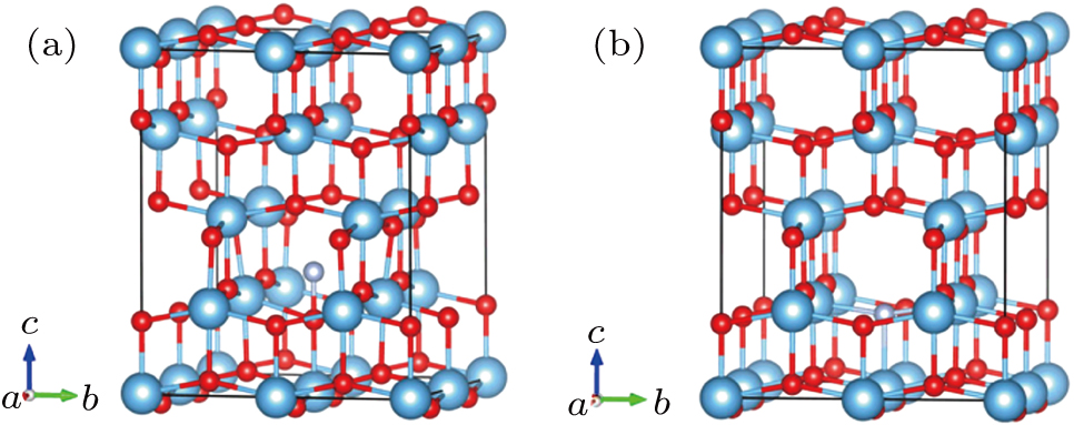
The DFT[29] calculations are carried out using the projector augmented wave (PAW) pseudopotentials-based Vienna ab initio simulation package code (VASP),[30] in which the exchange–correlation potential is the local density approximation (LDA). The values of onsite Coulomb interaction U within LDA for Ti 3d and O 2p states are 4.37 eV and 7.51 eV respectively.[31,32] As for N 2p states, the U value is selected as zero. Monkhorst–Pack k-point meshes of 4 × 4 × 4 are chosen for electronic property calculations. The electronic states are expanded using plane wave basis set with a cutoff energy at 450 eV. The energy at 5 × 10⁻⁶ eV is set as the convergence threshold for self-consistent field energy, and the atomic relaxations are performed until the residual forces are below 0.01 eV/Å. The (101) plane is chosen in the calculation because which is the dominant peak of TNTs according the results of experiment.[913] The two modeled anatase (101) nitrogen doping structures are shown in Fig. 1. In this paper, substitutional and interstitial nitrogen atoms are considered, denoted as S–N and I–N respectively. S–N doping is modeled as that an O atom is replaced by an N atom, which corresponds to the doping concentration of 2.08% in coincidence with the concentration used in the experiments. I–N doping is simulated by adding one nitrogen atom into the supercell. UV-Vis optical absorption calculations are performed following the methodology described in Ref. [33].

Fig. 1. The optimized I–N-doped anatase TiO2 (a), S–N-doped anatase TiO2 (b). The blue, red, and brown spheres represent Ti, O, and N atoms, respectively.
2.3. Characterization and PC degradation measurements

The morphologies of prepared samples are determined by field emission scanning electron microscope (FESEM, Hitachi SU8010) equipped with energy dispersion spectrometer (EDS). For the PC degradation experiments, MB, RhB, and BPA are selected. The initial concentrations are 80 mg/L for dyes and 50 mg/L for BPA respectively. For dissolution of BPA in water, the mixture is dealed with ultrasonic waves for 3 h. Before PC degradation, the TNTs and nitrogen-implanted TNTs (1 cm × 2 cm) are dipped in the solutions for 30 min to establish the equilibrium between adsorption and desorption. During PC degradation, all the samples are immersed in 3-ml solutions, and irradiated by visible and UV light. At given intervals, the photocatalysts are taken out and the solutions are analyzed using a UV-Vis spectrophotometer (Shimadzu UV-3600). After analysis, the photocatalysts are put into the reactor again for PC degradation.

The wavelengths used in absorbance measurements are 664 nm, 553 nm, and 277 nm for MB, RhB, and BPA, respectively. The removal efficiency of compound is examined according to the ratio of Ct and C0, where Ct and C0 are the absorbance of compound aqueous solution at time t and 0 at the analytical wavelength, respectively. The selected 365-nm UV light illumination is performed using a 500-W high-pressure mercury lamp. A 300-W tungsten–halogen lamp is chosen as the visible light source equipped with a cut-off filter with edge at 420 nm to remove UV light. The UV light intensity on the surface of samples is measured to be 213 μW/cm2 by UV irradiance meter (UV-A, BNU), while the flux of the visible light is found to be 10710 lx measured by illumination photometer (ST-85, BNU).

3. Results and discussion
3.1. Characterization of nitrogen ions-implanted TNTs
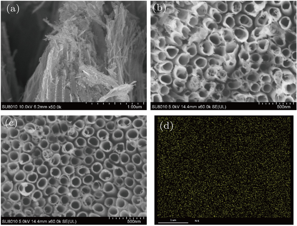
Figure 2 shows the SEM and EDS images. The concurrent production of defects is a significant drawback of ion implantation, which mostly hinders the activation of the implanted ions.[34] Usually, the damage can be recovered by subsequent annealing process after ion implantation, which means two annealing procedures need to be done before and after implantations for implanted TNTs. We choose prepared TNTs as the target of the ion implantation at the start. But, when the prepared TNTs are implanted using nitrogen ions with high energy (60 keV), highly ordered tubular structures of TNTs are severely destroyed (Fig. 2(a)). So, the method of anodization of nitrogen-implanted Ti foils is chosen, in which the direct bombardment of TNTs can be avoided, and only one annealing procedure after ion implantation is made for crystallization. It should be noted that the average inner tube diameter of the samples is in a range of 150 nm–170 nm (Figs. 2(b) and 2(c)), therefore, the change of tube diameter is not found with the same anodization conditions in the presence of different doses of implanted nitrogen ions. The wall thickness of N-10-TNTs on the surface is in a range of 15 nm–20 nm. However, lots of broken tubes due to over corrosion during anodization were found on the surface of TNTs. It is apparent that the surface of nitrogen ions-doped TNTs shows more ordered structures compared to TNTs, approving a better corrosion resistance of nitrogen ions-doped TNTs. Therefore, with increasing the dose of implanted ions, well organized and more compact tubular structures can be obtained. A possible reason is that a dense nitrogen-doped nanolayer will be presented on the top of Ti foils after implantation. Thus, the corrosion resistance of the implanted samples is increased for anodization, which leads to the corrosion rate of nitrogen-doped Ti foils being lower than pure Ti foils. As a result, implanted samples show more order tubular structure on the surface. The existence of nitrogen is measured by EDS. Figure 2(d) is the evidence of the well-dispersed nitrogen element on the top of N-10-TNTs. The results of EDS imply that a uniform distribution of nitrogen on the surface of TNTs has been attained using ion implantation method.

Fig. 2. Top views of SEM images of direct implanted TNTs under ion energy of 60 keV (a), TNTs (b), N-10-TNTs (c), EDS elemental mapping images of N-10-TNTs (d).
3.2. Theoretical computation

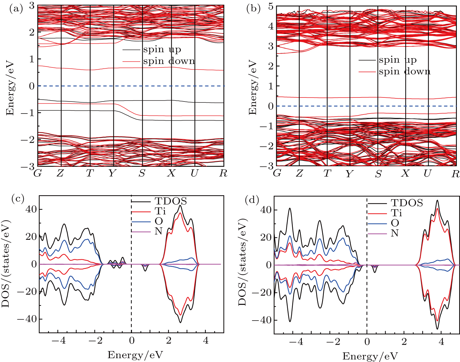
The band structure and density of states (DOS) of pure TiO2 are calculated, which are shown in Fig. S2. From the results, it can be seen that pure TiO2 is an indirect-gap semiconductor because the M and G points are corresponding to VB maximum and CB minimum respectively. The minimum BG width between VB maximum and CB minimum is about 3.21 V, which is in accordance with the experimental result of 3.2 eV. It is obviously that the VB of pure TiO2 is dominated by the O 2p states and the CB is mainly contributed by the Ti 3d states. The doped nitrogen atom not only affects the crystal structure of TiO2, but also influences its electronic structure and properties. For the cases of both I–N- and S–N-doped TiO2, the doped nitrogen atoms introduce four new states of N 2p orbitals in the BG. However, the new states locate at different positions. For the case of S–N, the new states are closer to VB maximum more, and connect with VB maximum in some regions. While the new states appear in the BG only to form impurity energy level for the case of I–N. So, S–N can reduce the BG width of TiO2. As shown in Figs. 3(a) and 3(b), the calculated band gaps are 3.21 eV and 3.1 eV for I–N- and S–N-doped TiO2, respectively. The BG of TiO2 after replacing oxygen with nitrogen atom is narrowed compared to pure TiO2 (3.2 eV), which is responsible for the redshift in the absorption edge. Regarding the I–N-doped TiO2, it can be observed that the Fermi level (EF) apparently locates in the middle of BG, while the EF of S–N-doped sample has no obvious moving. From the band stature of nitrogen-doped TiO2, the excitation energies corresponding to transitions from impurity states and the VB maximum to CB minimum can be calculated. Apparently, all these energies are smaller than those corresponding to BG width of the pure TiO2 (3.2 eV). These new formed states will become shallow donor or acceptor levels, which is undoubtedly beneficial to the PC ability of nitrogen-doped TNTs.

Fig. 3. The band structure of I–N-doped TiO2 (a), S–N-doped TiO2 (b). The density of states (DOS) of I–N-doped TiO2 (c), S–N doped TiO2 (d). The dashed lines represent the Fermi level EF.

To analyze the electronic structure of doped TiO2 further, the DOS and projected DOS are shown in Figs. 3(c) and 3(d). For the cases of I–N- and S–N-doped TiO2, it can be found that these new formed states are composed of the N 2p states mainly, and only a small part originates from O 2p states and Ti 3d states. This shows that both I–N and S–N have strong influence on their neighbor atoms to modify their DOS distributions. At the same time, the new states are formed in the BG of TiO2 through N 2p orbital hybridization with O 2p and Ti 3d orbitals. For the cases of I–N-doped TiO2, the energy of the highest occupied spin-up states distributes from −1.2 eV to −0.6 eV above the VB edge (Fig. 3(c)). This indicates that the I–N may act as the trap of photogenerated h+ under UV light irradiation, which will reduce the mobility and oxidizing power of h+ due to the higher energy of the trapping states in comparison with VB. However, visible light is absorbed by nitrogen-doped TiO2 because of the formation of the impurity states in the BG. From the comparison of the projected DOS of S–N-doped TiO2, the formation can be found for the N 2p impurity states near the VB maximum. The projection to the N 2p impurity states provides evidence for localized characters of these states. So, the doped nitrogen atoms induce about 0.1-eV reduction of the BG width between the occupied VB maximum and the unoccupied CB minimum, which is not the reason of a real shift of the VB edge but due to the generation of localized states in the BG.[35] The formation of an empty spin-down state in the middle of the BG is also found from Figs. 3(b) and 3(d).

To better understand the change of photocatalytic activity of nitrogen-doped TNTs, the UV-Vis absorption spectra of the S–N and I–N models are calculated and shown in Fig. 4. Our calculations show that the optical absorption edge for the pure TiO2 is about 3.2 eV. Compared with the pure TiO2, both S–N and I–N models have slight increase for absorption of visible light, showing a red-shift in the optical absorption edge. The band gaps of S–N and I–N models are reduced by 0.15 eV and 0.1 eV, respectively, which reduces the required energy for electronic transitions. The improved visible light response of S–N and I–N models is advantageous to the solar energy conversion efficiency.

Fig. 4. The optical absorption of TiO2 and I–N-doped TiO2 and S–N-doped TiO2.
3.3. degradation of MB, RhB, and BPA

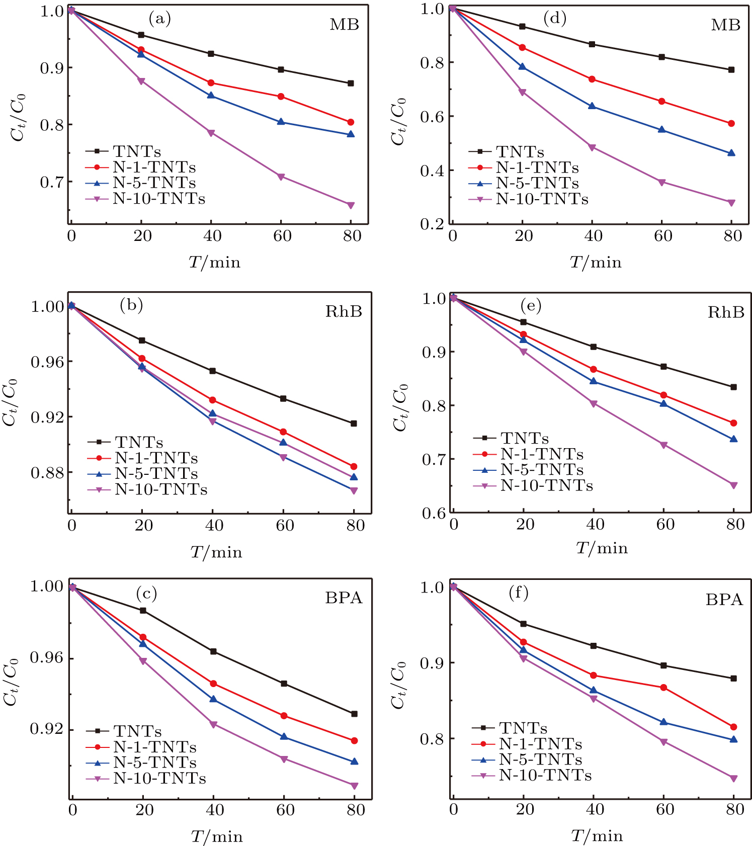
The PC activities of TNTs and nitrogen-doped TNTs have been evaluated under both visible and UV light irradiations. Figures 5(a)5(c) show the degradation results under visible light illumination. It was obviously that TNTs exhibit low activity. The degradation rate of MB is merely 13% after 80-min decomposition. However, after implantation, the activity was greatly enhanced. It has been found that the dose of implanted nitrogen ions significantly affects the PC activities of TNTs. When the dose of implanted ions is increased from 1 × 10¹⁷ to 1 × 10¹⁸, the activities of the nitrogen ions-doped TNTs are improved gradually. The N-10-TNTs show the best activity for the degradation of MB under visible light illumination, and 34% of MB is degraded after 80 min. Furthermore, it is found that the PC degradations of MB over TNTs and nitrogen-doped TNTs can be described by a pseudo-first order kinetics (shown in Fig. S3) with the formula below: ln (C0/Ct) = kt, where k is the kinetic constant, which is listed in Table 1.

Fig. 5. Comparison of PC degradation activity for TNTs and nitrogen ions-implanted TNTs under light irradiation: (a)–(c) visible; (d)–(f) UV.
Table 1.

The PC rate for the degradation of MB, RhB, and BPA on different samples.

.

The k of MB degradation with TNTs under visible light irradiation is only about 0.00179 min−1. However, for the nitrogen ions-doped TNTs, all the k values are enhanced. For example, the k for N-10-TNTs is up to 0.00582 min−1, which is about 3.3 times higher than that of TNTs. In addition, RhB and BPA are degraded by TNTs and nitrogen-doped TNTs to evaluate the activities of the samples further. As shown in Figs. 5(b) and 5(c), the nitrogen ions-doped TNTs exhibit higher PC performance than TNTs for the degradation of RhB and BPA under visible light irradiation. After 80 min, only 8.5% RhB and 7.1% BPA are degraded by TNTs. In the same time, the N-10-TNTs exhibits the highest PC activity, about 12.4% RhB and 11.1% BPA are degraded. The results show that the N-10-TNTs reveal a superior PC activity than that of TNTs during the RhB and BPA degradation processes. The k of N-10-TNTs is about 1.5 and 1.8 times higher than that for TNTs. The degradation results of the three organic pollutants reveal that N-10-TNTs is an efficient broad spectrum photocatalyst excited by visible light. The outstanding performance ensures nitrogen ions-implanted TNTs to be valuable photocatalyst removing pollutants of the environment. According to Ref. [22,3643] and our theoretical computation, both I–N and S–N in the lattice of TO2 will produce energy levels within the BG. Meanwhile, oxygen vacancies and Ti3+ are formed during ion implantation which also creates energy levels in the band gap, because the nitrogen doping induces a substantial reduction of the formation energy of Ti3+ and oxygen vacancies in TiO2.[44] When nitrogen ions-doped TNTs are irradiated by visible light, photogenerated electrons jump from N 2p energy level to CB or from VB to the energy level associated with Ti3+ states and oxygen vacancies, leaving positive holes in N 2p energy level and VB. So, suitable doped nitrogen ions are beneficial to the absorption of visible light, and the separation and fast transfer of carriers, resulted in extended carriers’ lifetime associating with the improvement of PC activities.

Figures 5(d)5(f) show the degradation results under UV light irradiation. Nearly 72% of MB was degraded with 80-min irradiation in the presence of N-10-TNTs, indicating its excellent PC activity. The TNTs only degraded 22.8% of MB under the same conditions. The k for N-10-TNTs is up to 0.01661 min−1, which is about 5 times higher than that for TNTs. The RhB and BPA degradations using TNTs and nitrogen-doped TNTs are also investigated under the identical conditions. The results indicate that nitrogen-doped TNTs are a much better photocatalyst than TNTs under UV light irradiation. As can be seen from Figs. 5(e) and 5(f), the degradation ratios for RhB and BPA are significantly increased to 34.8% and 25.2% over N-10-TNTs under UV light irradiation for 80 min. The k for N-10-TNTs is about 2.3 and 2.1 times higher than that for TNTs. Irradiated by UV light, TNTs and nitrogen-doped TNTs exhibit a higher efficiency of decomposition dyes and chemical character than by visible light. This trend is also ascribed to N 2p energy level in the BG above the VB band due to S–N and I–N in the TiO2 lattice. Irradiated by UV light, electrons are excited from both VB and N 2p energy levels, but electron transitions only occurr from the N 2p energy levels irradiated by visible light. So, more holes are produced under UV light irradiation, which is corresponding to higher photocatalytic efficiency. However, it should be noticed that the sum of PC efficiency of TNTs under UV light irradiation and N-10-TNTs under visible light irradiation is lower than the PC efficiency of N-10-TNTs under UV light irradiation. It is reasonable that the electrons of N 2p energy level do not exited completely under visible light irradiation. Furthermore, it is probable that most of electrons are excited to the CB of the samples due to higher photo energies under UV light irradiations, resulting in more active carriers. The number of excited electrons increases with increasing dose of implantation. As a result, the photocatalytic efficiency of implanted samples under UV light irradiations are far above visible light irradiations.

3.4. Possible PC degradation mechanism

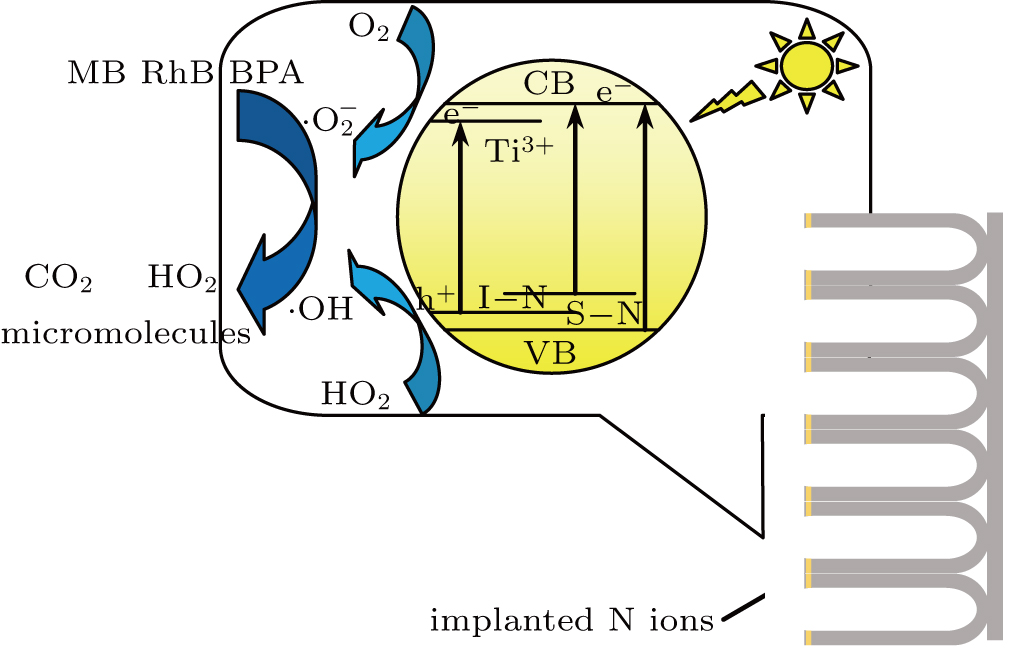
According to the experimental and theoretical results mentioned above, the reasonable mechanism of PC of dyes and chemicals under visible and UV light irradiation is presented in Fig. 6. Because of formations of S–N (N 2p localized states) and I–N (N–O band) levels, the electronic and band structures of TiO2 are modified by introducing localized states at the top of the valence band (VB) on account of the doping of interstitial and substitutional nitrogen ions in the crystal lattice of TiO2, and the BG of TiO2 in prepared nanotubes is narrowed. Moreover, these nitrogen levels are excellent traps for the Ti3+ electrons deriving from oxygens vacancies, which facilitate the creation of Ti3+ and oxygens vacancies to produce ⋅O2−. Therefore, when nitrogen-doped TNTs are irradiated with visible light, the excited electrons will jump from the VB and N 2p energy levels to the CB and impurity energy levels (associated with the presence of oxygens vacancies and Ti3+), leaving holes in VB and N 2p energy levels. Meanwhile, oxygen can be reduced to produce by photogenerated electrons, and ⋅OH radicals can be generated by holes. These strong oxidizing radicals and holes could decompose dyes and chemicals into macromolecules, CO2 and H2O on the surface of TNTs and nitrogen-doped TNTs in both PC degradations. While irradiating with UV light, electrons will be excited from both the VB and the N 2p energy levels, and then more holes are produced corresponding to higher photocatalytic efficiencies than those under the visible light illumination.

Fig. 6. Schematic illustration of production and transfer of carriers during PC degradation for nitrogen-doped TNTs under light irradiation.
4. Conclusions

The PC performance of nitrogen-doped TNTs synthesized by ion implantation is improved significantly under both visible and UV light irradiations. The experimental and computational results indicate that impurity energy levels from S–N and I–N dopants are critical for PC performance. The results of PC degradation show that the electrons of CB minimum originate from different excited ways when the implanted samples are irradiated under visible and UV light. The TNTs prepared using ion implantation and anodization show significant visible and UV light-induced PC activity, which could open exciting new opportunities in doping modification of TNTs, especially suitable for doping various non-metal and metal ions into TNTs to improve PC performance.

Reference
[1] Resolution A/R E S/64/292 The human right to water, sanitation United Nations General Assembly 2010 https://www.un.org/en/ga/search/view_doc.asp?symbol=A/RES/64/292
[2] Keane D A Mcguigan K G Ibáñez P F Polo-López M I Byrne A J Dunlop P S M O’Shea K Dionysiou D D Pillai S 2014 Catal. Sci. Technol. 4 1211
[3] Fang W Xing M Zhang J 2017 J. Photoch. Photobio. 32 21
[4] Reddy P V L Kim K H Kavitha B Kumar V Raza N Kalagara S 2018 J. Environ. Manage. 213 189
[5] Pelaez M Nolan N T Pillai S C Seery M K Falaras P Kontos A G Dunlop P S M Hamilton J W J Byrne J A O’Shea K Entezari M H Dionysiou D D 2012 Appl. Catal. B-Environ. 125 331
[6] Froschl T Hormann U Kubiak P Kučerova G Pfanzelt M Weiss C K Behm R J Hüsing N Kaiser U Landfester K Wohlfahrt-Mehrens M 2012 Chem. Soc. Rev. 41 5313
[7] Fujishima A Zhang X T Tryk D A 2008 Surf. Sci. Rep. 63 515
[8] Bakar S A Ribeiro C 2016 J. Photoch. Photobio. 27 1
[9] Ge M Z Cao C Y Huang J Y Li S H Zhang S N Deng S Li Q S Zhang K Q Lai Y K 2007 Nanotechnol. Rev. 5 75
[10] Regonini D Bowen C R Jaroenworaluck A Stevens R 2013 Mater. Sci. Eng. 74 377
[11] Kowalski D Kim D Schmuki P 2013 Nano Today 8 235
[12] Lee K Mazare A Schmuki P 2014 Chem. Rev. 114 9385
[13] Zubair M Kim H Razzaq A Grimes C A In S 2018 J. CO2 Util. 26 70
[14] Zhang Y Cui W Q An W J Liu L Liang Y H Zhu Y F 2018 Appl. Catal. B-Environ. 221 36
[15] Ji L J Zhang Y H Miao S Y Gong M D Liu X 2017 Carbon 125 544
[16] Georgieva J Valova E Armyanov S Tatchev D Sotiropoulos S Avramova I Dimitrova N Hubin A Steenhaut O 2017 Appl. Sur. Sci. 413 284
[17] Wang M Y Ioccozia J Sun L Lin C J Lin Z Q 2014 Energy Environ. Sci. 7 2182
[18] Zaleska A 2008 Recent Pat. Eng. 2 157
[19] Devi L G Kavitha R 2014 RSC Adv. 4 28265
[20] Wang W Tadé M O Shao Z P 2018 Prog. Mater. Sci. 92 33
[21] Etacheri V Valentin C D Schneider J Bahnemann D Pillai S C 2015 J. Photoch. Photobio. 25 1
[22] Lynch J Giannini C Cooper J K Loiudice A Sharp I D Buonsanti R 2015 J. Phys. Chem. 119 7443
[23] Jiang X D Guan X Y Huang J J Fan X L Xue D S 2019 Acta Phys. Sin. 68 126102 in Chinese
[24] Dai L H Bi D W Hu Z Y Liu X N Zhang M Y Zhang Z X Zou S C 2018 Chin. Phys. 27 048503
[25] Zhou X M Hublein V Liu N Nguyen N T Zolnhofer E M Tsuchiya H Killian M S Meyer K Frey L Schmuki P 2016 Angew. Chem. Int. Ed. 55 3763
[26] Wang G M Xiao X H Li W Q Lin Z Y Zhao Z P Chen C Wang C Li Y J Huang X Q Miao L Jiang C Z Huang Y Duan X F 2015 Nano Lett. 15 4692
[27] Han L Xin Y J Liu H L Ma X X Tang G Z 2010 J. Hazard. Mater. 175 524
[28] Li J Hou X G Sun T T Han J Liu H L Li D J 2019 Surf. Coat. Tech. 365 123
[29] Wang G S Lin Y M Zhao Y L Jiang Z Y Dong X 2018 Acta Phys. Sin. 67 233101 in Chinese
[30] Kresse G Furthmuller J 1996 Phys. Rev. 54 1169
[31] Tian P L Jiang Z Y Zhang X D Zhou B Dong Y R Liu R 2017 Chin. Phys. 26 087102
[32] Yu D D Zhou W Liu Y Y Zhou B Z Wu P 2015 Phys. Lett. 379 1666
[33] Liu Y Y Zhou W Wu P 2017 Mater. Chem. Phys. 186 333
[34] Ronning C Borschel C Geburt S Niepelt R 2010 Mater. Sci. Eng. 70 30
[35] Finazzi E Valentin C D Selloni A Pacchioni G 2007 J. Phys. Chem. 111 9275
[36] Xia L Yang Y Cao Y Liu B Lia X X Chen X Y Song H Zhang X M Gao B Fu J J 2019 Surf. Coat. Tech. 365 237
[37] Peighambardoust N S Asl S K Mohammadpour R Asl S K 2018 Electrochim. Acta 270 245
[38] Yuan B Wang Y Bian H D Shen T K Wu Y C Chen Z 2013 Appl. Surf. Sci. 280 523
[39] Mazierski P Nischk M Gołkowska M Lisowski W Gazda M Winiarski M J Klimczuk T Zaleska-Medynska A 2016 Appl. Catal. B-Environ. 196 77
[40] Kodtharin N Vongwatthaporn R Nutariya J Sricheewin C Timah E N Sivalertporn K Thumthan O Tipparach U 2018 Mater. Today-Proc. 5 14091
[41] Souza J S Krambrock K Pinheiro M V B Ando R A Guha S Alves W A 2014 J. Mol. Catal. A-Chem. 394 48
[42] Garcia-Segura S Brillas E 2017 J. Photoch. Photobio. 31 1
[43] Xu Y Ahmed R Klein D Cap S Freedy K Mcdonnell S Zangari G 2019 J. Power Sources 414 242
[44] Pan X Y Yang M Q Fu X Z Zhang N Xu Y J 2013 Nanoscale 5 3601