Thermal desorption characteristic of helium ion irradiated nickel-base alloy
Lv Shasha1, †, Zhu Rui2, Zhao Yumeng3, Li Mingyang3, Wang Guojing4, Qiu Menglin1, Liao Bin1, Hua Qingsong1, Cheng Jianping1, Li Zhengcao5, ‡
Key Laboratory of Beam Technology and Material Modification, Ministry of Education, College of Nuclear Science and Technology, Beijing Normal University, Beijing 100875, China
Institute of Nuclear and New Energy Technology, Tsinghua University, Beijing 100084, China
Department of Engineering Physics, Tsinghua University, Beijing 100084, China
School of Physical Science and Technology, Lanzhou University, Lanzhou 730000, China
Key Laboratory of Advanced Materials (MOE), School of Materials Science and Engineering, Tsinghua University, Beijing 100084, China


† Corresponding author. E-mail: lvss@bnu.edu.cn zcli@mail.tsinghua.edu

Abstract

The nickel-base alloy is one of the leading candidate materials for generation IV nuclear reactor pressure vessel. To evaluate its stability of helium damage and retention, helium ions with different energy of 80 keV and 180 keV were introduced by ion implantation to a certain dose (peak displacement damage 1–10 dpa). Then thermal desorption spectroscopy (TDS) of helium atoms was performed to discuss the helium desorption characteristic and trapping sites. The desorption peaks shift to a lower temperature with increasing dpa for both 80 keV and 180 keV irradiation, reflecting the reduced diffusion activation energy and faster diffusion within the alloy. The main release peak temperature of 180 keV helium injection is relatively higher than that of 80 keV at the same influence, which is because the irradiation damage of 180 keV, helium formation and entrapment occur deeper. The broadening of the spectra corresponds to different helium trapping sites (He–vacancies, grain boundary) and desorption mechanisms (different HenVm size). The helium retention amount of 80 keV is lower than that of 180 keV, and a saturation limit associated with the irradiation of 80 keV has been reached. The relatively low helium retention proves the better resistance to helium bubbles formation and helium brittleness.

PACS: ;07.20.-n;;28.41.Qb;
1. Introduction

Irradiation of energetic particles produces a large number of irradiation defects,[1] such as interstitial atoms, vacancies, dislocation rings, voids, and bubbles. The interstitial atoms and vacancies further evolve and aggregate to form clusters, gap/vacancy dislocation rings, stacking fault tetrahedrons, voids,[2] etc. Furthermore, it can cause materials swelling, rapid creep, hardening, and embrittlement, which accelerates the degradation of the material macroscopic properties and seriously threatens the safe operation and service life of nuclear reactors.[3,4] Therefore, the nuclear materials are critical to the successful operation of nuclear energy systems.

Structural materials used in generation IV nuclear power plants should maintain integrity when serving in high temperature environment.[5] Also, they could undergo high neutron doses ranging from tens to hundreds of displacement per atom (dpa) according to their different positions to the reactor core. A recent review of the radiation effect on nickel-base alloys indicated that the main cause of embrittlement is the transmutation-induced helium and hydrogen.[6] However, the irradiation effects on nickel-based superalloy are little understood compared to the widely used stainless steel. Therefore, it is necessary to obtain the new experimental data of nickel-base alloys in order to predict their performance after long service in harsh environment.

When nickel is irradiated by high energy particles and neutrons, helium atoms are generated by the nuclear reaction of (.[7] Due to the extremely low solubility of helium atoms, they tend to make swelling and ductility degraded. Helium, which has a strong interaction with vacancies,[8] can form a high density of He–vacancy clusters. Then, the He–vacancy clusters subsequently grow by absorbing more vacancies to form He bubbles. cluster is the lowest size class of helium bubbles and plays an important role in the initial stage nucleation, aggregate, and precipitate into helium bubbles.[9] While, segregation of other alloying elements, such as the minor elements Si in Ni alloys, can suppress the formation of voids. The formation of interstitial-type dislocation loops and voids can be suppressed due to the recombination of interstitials and vacancies at defect sinks.[10] It has been reported[11] that dislocations can also act as helium trapping sites in Ni irradiated by 5 keV at room temperature, and helium is released at 940 K during thermal annealing.

The interactions among helium atoms, , helium bubbles, and different alloy elements have various effects on the microstructure and macro-properties of nickel alloys.[12,13] At low irradiation temperature, the movement rate of the group and defects is slow, and the growth of helium bubbles is inhibited.[14] In the nickel matrix, free He atoms aggregate or form a single interstitial atom (SIA), nucleate and grow combined with vacancies, making helium bubbles small in size and high in pressure.[15] Due to the different size of the helium atom defects group, the corresponding research methods are also different.[16] The helium defect diffuses to the surface in the form of interstitial atoms and releases on the surface.[17,18] Therefore, thermal desorption spectropy (TDS) can analyze helium bubbles with small size, and each characteristic peak may represent a different desorption process.[19,20] Supplementary to conventional mechanical measurements, now it is the simplest, most practical, and indirect method to study the behavior of helium and their defects (a single atom, and bubbles).[21]

In the present studies, a nickel alloy, has been chosen to investigate the helium damage and desorption. From release peaks of TDS, the amount of helium desorption, helium trapping sites, helium retention behavior, and the dissociation characteristics are inferred.

2. Experimental details

The specimens were prepared by grinding with SiC grit paper and polishing with 0.02 m colloidal silica suspension, then the specimens were irradiated by He ions with an energy of 80 keV or 180 keV at room temperature with different doses (from 1 dpa to 10 dpa). In the process of ion implantation, the target chamber was kept at a high vacuum of Pa to avoid oxidation of the material surface during ion implantation. Afterwards, thermal desorption spectroscopy (TDS) was performed by heating the samples at 10 C/min to C. The helium atoms can be held at different trapping sites within the material, and when the specimen is heated, the adsorption energy of the specific trapping sites is overcome to release the helium. To monitor this, a temperature controlled electric furnace (from a Quantachrome Instruments ChemBET Pulsar TPR/TPD Automated Chemisorption Analyzer) and a quadrupole mass spectrometer (ThermoStar Gas Analysis System) under high vacuum conditions were used. Once the trapping energy (temperature) is reached, the recorded spectrum of helium concentration will show a peak, which can be used to calculate the number of helium atoms released.

The concentration reading given by the mass spectrometer could not be used directly, and a calibration using a mixture of argon and helium was carried out, where argon was the inert carrier gas used in the experiment. At any given time during the experiment, the following relationship holds:

where is the actual concentration of (not the reading given by the mass spectrometer), is a constant relating the actual concentrations of the gases to their currents given by the mass spectrometer readout, is the current readout of the gas , and is the total flow rate of the gas (sum of the gas cylinder flow rate and any desorption for He, while just the flow rate from the gas cylinder for Ar).

During heating, with carrier Ar used (He supply switched off), the unknown quantity to be calculated (helium desorption) is given by the above. is known from the gas flow meter setting, and is known from the mass spectrometer recordings. The constant is unknown, and must be calculated via a calibration. With the constant calculated, a modified version of the relationship above was used to calculated from the helium desorption during heating to 1000 C (at which the temperature remained for at least 15 min), at 1 , from room temperature,

Here, is the argon flow rate set equal to 20 mL (20 sccm), 60 s/min is used to convert the to minutes, and is the desorption value to be calculated (in ml). is summed over the peak temperature interval (the time of peak occurred), with being the time between readings. is the argon current reading at a given time. is the helium desorption current at a given time, and equals to the He current reading in the peak minus the background He current.

3. Results and discussion
3.1. TRIM calculation

The chemical composition of the alloy is presented in Table 1. The ion irradiation experiments were performed using an 80 kV ion implanter at Beijing Normal University at room temperature. The specimens were irradiated with 80 keV and 180 keV helium ions. The fluences on the specimens irradiated with 80 keV helium ions were ions/cm ions/cm ions/cm2, and (corresponding to the peak doses of 1 dpa, 2.5 dpa, 5 dpa, and 10 dpa). The fluences irradiated with 180 keV helium ions were , and , the same as the above peak doses, respectively. It should be mentioned that the fluence on the specimens irradiated with 180 keV helium ions is lower than that with 80 keV helium ions under the same dose. The irradiation damage and implanted helium ions profiles were predicted by SRIM (Stopping and Range of Ions in Matter) 2013 program using the Kinchin-Pease quick calculation mode[22] and the displacement threshold energy was set to 40 eV. The lattice binding energy was set to zero in order to be fully consistent with the model and sputtering was not accounted for in the calculation.

Table 1.

Chemical composition of the nickel alloy (wt.%).

.

The distributions of displacement damage (dpa) and He ion concentration with depth are displayed in Figs. 1(a) and 1(b). The irradiation damage depth induced by 80 keV and 180 keV helium ions was approximately 450 nm and 700 nm with a peak damage at 230 nm and 440 nm, respectively. It should be noticed that the irradiation damage had a shallower peak than the distribution of the helium ions because the helium ions energy near the end of tracks is too low to create abundant cascades. In addition, figures A1(a) and A1(b) show the depth profiles of helium and vacancy concentration at 80 keV and 180 keV, respectively.

Fig. 1. Depth profiles of dpa and helium concentration in nickel alloy irradiated with (a) 80 keV and (b) 180 keV helium ions to the dose of 2.5 dpa calculated by SRIM.
3.2. TDS analysis

Vacancies, dislocations, grain boundaries, and other defects have strong ability to bind helium atoms, which can serve as the preferred nucleation region of helium bubbles. When there are some inherent defects in the matrix, or the defects resulted from helium irradiation, the helium atoms will diffuse directly to these defects and aggregate into helium bubble nuclei. The helium bubbles are brought to the grain boundary with movable dislocations, then they move to the phase boundaries and surface.[24] The energy and movement mechanism of helium atoms in Ni-base alloy can be inferred from the release peaks. When different types of helium trapping site’s adsorption enthalpy are reached, the current appears high values and shows various peaks. The actual helium desorption current was calculated using the difference between the baseline value and the measured peak values. To extract the base line, the trendline was used by the polynomial fit, of which the order was varied between 2nd and 5th to get the best fit. The base line values were then calculated using the equation of the line. In order to get the baseline values accurate enough, the number of significant figures used was at least three more than the order of the polynomial.[25]

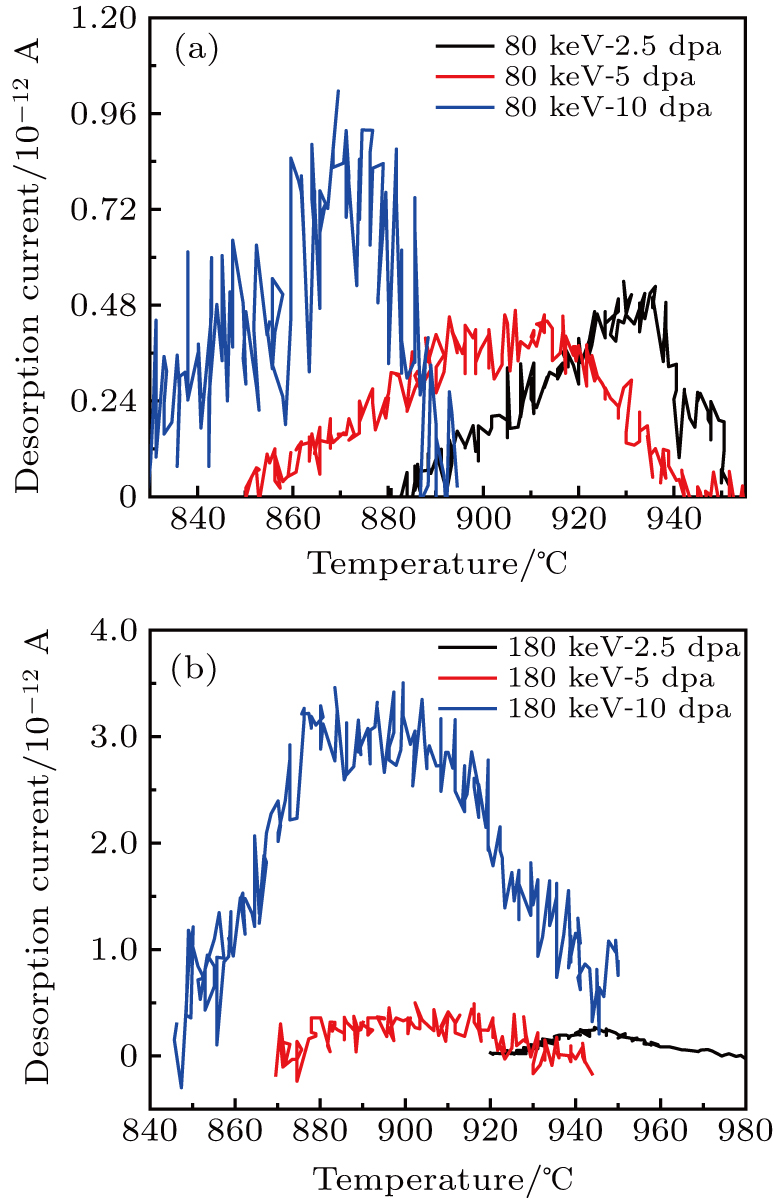
Figure 2 shows the typical He ion current with temperature obtained for each TDS run. Peaks were observed in the temperature range of 800–1000 °C, corresponding to the desorption of He from the trapping sites. Data of the specimens (80 keV–1 dpa and 180 keV–1 dpa) are missing from Fig. 2, which is because no peak was identifiable from the data. From the peak shape analysis, the release peak is asymmetric and has the characteristics of the first-order reaction desorption curve.

Fig. 2. The desorption peaks obtained for different irradiation doses on each specimen.

The data shows a trend that the peaks of the specimen with the higher dpa move to a lower temperature range. For the 80 keV helium implanted alloy, the desorption peak appears at the temperatures of ∼ 930 °C, 900 °C, and 870 °C for 2.5 dpa, 5 dpa, and 10 dpa, while it shows peak at ∼ 950 °C, 900 °C, and 880 °C for 2.5 dpa, 5 dpa, and 10 dpa of 180 keV irradiation. The shift of the main peak position reflects the change of the diffusion activation energy. In addition, it suggests there is a lower adsorption enthalpy for helium in the nickel alloy at higher irradiation damage/fluence. This could be the result of the formation of irradiation induced lattice defects and vacancy clusters, which allow for faster and lower activation energy diffusion within the alloy. Another observation is that the 80 keV peaks all occur at a lower temperature than the 180 keV ones for the equivalent dpa, showing that less energy is required for desorption, or less time for it to start occurring. For the 180 keV irradiation, the induced damage, , helium bubbles formation and entrapment occur deeper within the material, so as to take longer time for desorption to occur. It can be inferred that the case with 80 keV is more of a surface effect, the helium atoms are not as much penetration into the specimen.

From the peak broadening, it is reasonable to infer that there are many different forms of activation energy, or many adsorption forms with different adsorption enthalpy. The different helium desorption peaks correspond to different helium trapping sites. The formation energy of He and vacancy is about one half of that of interstitial He atom. In the grains, the preferred occupied area of He atom is vacancy, rather than dislocations. While the most advantageous location to accommodate He atoms is the grain boundary. The desorption current in the low temperature could be attributed to the solid helium interaction of interstitials and dislocations in the grain boundary, and the desorption current in the high temperature to its release from the cavities.

The desorption temperature is higher than 900 °C (0.5Tm), corresponding to the release of the trapped helium from the cavities. The adsorption enthalpy of He atoms to different cavities is different. The thermal desorption of He corresponds to a single He atom desorbing from the bound states of vacancy groups of different sizes. With the increase of temperature, the average size of residual should be smaller and the dissociation energy should be larger. The lower the desorption peak temperature, the larger the corresponding .[21] In other words, the peaks of helium thermal desorption at lower temperature are related to these large cavities. The range of the temperatures (and therefore energy) that the peaks occur increases with greater dpa, meaning the desorption process of the irradiation damaged specimens of 10 dpa is more complex, including different activation energy processes.

3.3. Helium desorption amount

The total number of helium atoms desorbed can then finally be calculated using the equation

where is the number of helium atoms (given as , is Avogadro’s constant, 1000 mL/L is used to convert to L, and 22.4 L/mol is the gas constant used at standard temperature and pressure (assumed for the case of this calculation).

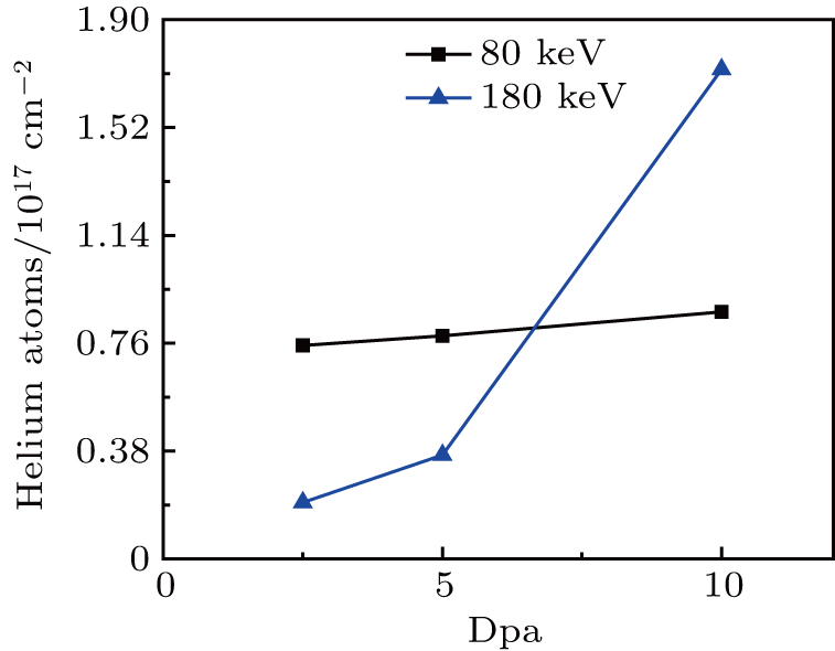
Figure 3 shows a plot of the total helium desorption with different energy and dpa. As shown in Table 3, the numbers of helium atoms desorbed are , and for 80 keV–2.5 dpa, 80 keV–5 dpa, and 80 keV–10 dpa, respectively. For the specimens of 80 keV–2.5 dpa, 80 keV–5 dpa, and 80 keV–10 dpa, the number of helium atoms desorbed are , and . Initially the energy of 80 keV results in a shallow injection depth, and the helium desorption amount is close and relative less. The 80 keV specimens did not show the increasing trend, and a saturation limit associated with the irradiation has been reached. One point needs to be mentioned is that some He atoms had already run out before the thermal desorption tests.

Fig. 3. Helium desorption amount for different irradiation and fluence which showed a desorption peak.
Table 2.

The irradiation influences, helium desorption amount, and retention percent of different irradiation specimens.

.

Based on the 180 keV specimens, it is thought that the total helium desorption increases with dpa. The greater the irradiation damage, the more helium is likely to be trapped within the specimen. This helium desorption behavior suggests that diffusion is the rate limiting step.

4. Conclusion and perspectives

From the TDS release peaks, the helium dissociation characteristics, trapping sites, and helium retention of nickel alloy are discussed. The desorption peaks shifted to a lower temperature with a higher dpa, suggesting the greater irradiation damage induced lattice defects and lower activation diffusion enthalpy. The TDS peaks suggested different helium trapping mechanisms. The peak broadening of higher dpa corresponds to many different forms of activation energy, and adsorption forms with different adsorption enthalpy. With higher dpa, the temperature range of the peaks increased, because the greater irradiation damage with more complex process made helium atoms desorbed from the grain boundary and different size. The 80 keV peaks occurred at a lower temperature (or time) than the equivalent 180 keV peaks, which could be a time-dependent effect that the irradiation damage, helium formation and entrapment occurred deeper in the 180 keV specimen. Helium trapped in the 80 keV specimen showed a saturation limit. While for the 180 keV specimens, it was thought that the total helium desorption increased with dpa. The ratio of helium retention amount and irradiation influence showed the good high-temperature stability.

Reference
[1] Gong Y Jin S Lu E Kuang P Zhu T Cao X Guo L 2018 Philos. Mag. 98 95
[2] Ren W Swindeman R 2009 J. Press. Vess. 131 044002
[3] Chen H C 2018 Nucl. Instrum. Meth. 421 50
[4] Fu C C Willaime F 2005 Phys. Rev. 72 064117
[5] Murty K Charit I 2008 J. Nucl. Mater. 383 189
[6] Stopher M 2017 Mater. Sci. Technol. 33 518
[7] Trinkaus H Singh B 2003 J. Nucl. Mater. 323 229
[8] Chen H Li D Lui R Huang H Li J Lei G Huang Q Bao L Yan L Zhou X 2016 Nucl. Instrum. Meth. 377 94
[9] Trinkaus H 1983 Radiat. Eff. 78 189
[10] Morishita K Sugano R Wirth B D de La Rubia T D 2003 Nucl. Instrum. Meth. 202 76
[11] Liu J Huang H Gao J Zhu Z Li Y 2019 J. Nucl. Mater. 517 328
[12] Gong H Wang C Zhang W Xu J Huai P Deng H Hu W 2016 J. Nucl. Mater. 368 75
[13] Lei G Xie R Huang H Liu R Huang Q Li J Zhou Y Li C Lei Q Deng Q 2018 J. Alloy. Compd. 746 153
[14] Rowcliffe A F Mansur L K Hoelzer D T Nanstad R K 2009 J. Nucl. Mater. 392 341
[15] Oono N Ukai S Kondo S Hashitomi O Kimura A 2015 J. Nucl. Mater. 465 835
[16] Zhou X Huang H Xie R Thorogood G Yang C Li Z Xu H 2015 J. Nucl. Mater. 467 848
[17] Wan H Ding Z Wang J Yin Y Guo Q Gong Y Zhao Z Yao X 2019 Surf. Coat. Tech. 363 34
[18] Yan Z Liu S Xia S Zhang Y Wang Y Yang T 2018 J. Nucl. Mater. 505 200
[19] Atsumi H 2003 J. Nucl. Mater. 313-316 543
[20] Carvalho I Schut H Fedorov A Luzginova N Sietsma J 2013 J. Nucl. Mater. 442 S48
[21] Cao X Xu Q Sato K Yoshiie T 2011 J. Nucl. Mater. 412 165
[22] Stoller R E Toloczko M B Was G S Certain A G Dwaraknath S Garner F A 2013 Nucl. Instrum. Meth. 310 75
[23] https://www.srim.org/
[24] Chernikov V Trinkaus H Jung P Ullmaier H 1990 J. Nucl. Mater. 170 31
[25] Xin Y Ju X Qiu J Guo L Chen J Yang Z Zhang P Cao X Wang B 2012 Fusion Eng. 87 432