


Design of diamond-shape photonic crystal fiber polarization filter based on surface plasma resonance effect
Cite this Article
Zhang Yongxia, Yuan Jinhui, Qu Yuwei, Zhou Xian, Yan Binbin, Wu Qiang, Wang Kuiru, Sang Xinzhu, Long Keping, Yu Chongxiu. Design of diamond-shape photonic crystal fiber polarization filter based on surface plasma resonance effect. Chinese Physics B, 2020, 29(3): 034208 
Permissions
Design of diamond-shape photonic crystal fiber polarization filter based on surface plasma resonance effect
† Corresponding author. E-mail:
Project supported by the National Natural Science Foundation of China (Grant Nos. 61875238 and 61935007).
Abstract
A novel plasmonic polarization filter based on the diamond-shape photonic crystal fiber (PCF) is proposed. The resonant coupling characteristics of the PCF polarization filter are investigated by the full-vector finite-element method. By optimizing the geometric parameters of the PCF, when the fiber length is 5 mm, the polarization filter has a bandwidth of 990 nm and an extinction ratio (ER) of lower than –20 dB. Moreover, a single wavelength polarization filter can also be achieved, along with an ER of –279.78 dB at wavelength 1.55 μm. It is believed that the proposed PCF polarization filter will be very useful in laser and optical communication systems.
1. Introduction
Photonic crystal fibers (PCFs) have been attracting great interest due to their unique optical properties such as adjustable dispersion,[1–4] high nonlinearity,[5] and large birefringence.[6–9] When the light is propagated inside PCFs coated with the metal films or filled with the metal wires, the free electrons on the metal surface interact with the incident light field, forming the surface plasma resonance (SPR).[10] The PCF polarization-related devices based on the SPR effect have potential applications in many fundamental and applied sciences.[11–18] The PCF polarization filter is one of the most important devices.
In 2007, Zhang et al.[19] selectively coated a silver film on the PCF holes using the chemical vapor deposition method. In 2008, Lee et al.[20] proposed the melt-filling gold technology to fill a gold wire into the PCF air hole. After that, many research works are concentrated on the PCFs which are filled or coated with different metals,[21–24] and the PCF polarization filter based on the SPR effect becomes feasible. In 2013, Xue et al.[25] reported an SPR-based PCF polarization filter, in which the confinement loss of the y-polarized core mode at wavelength 1.31 μm was 508 dB/cm. In 2015, Liu et al.[26] demonstrated a broadband PCF polarization filter based on the SPR effect, whose bandwidth was up to 430 nm. In 2017, Li et al. achieved a dual-wavelength PCF polarization filter, whose confinement losses induced by the SPR effect were 265.04 dB/cm and 230.5 dB/cm at wavelengths 1.31 μm and 1.55 μm, respectively.[27] In 2018, Wang et al.[28] reported a broadband PCF polarization filter with a large diameter gold-coated air hole, whose bandwidth covers the whole communication wave band.
In this paper, a novel plasmonic polarization filter based on the diamond-shape PCF is proposed. The confinement loss and resonant coupling characteristics of the proposed PCF polarization filter are investigated, and the influences of the fiber geometric parameters on the confinement loss are analyzed. By adjusting the fiber geometric parameters, a single wavelength polarization filter with an extinction ratio (ER) of −279.78 dB at wavelength 1.55 μm is achieved.
2. The PCF design and theory
Figure
 | Fig. 1. The schematic diagram of the proposed PCF polarization filter. |
The full-vector finite-element method is employed to investigate the coupling characteristics of the designed PCF polarization filter between the core mode and surface plasma polariton (SPP) modes. Because of the air hole coated with the gold film, the core-guided mode occurs to resonate with the SPP modes at some specific wavelengths, resulting in large confinement loss of the core mode. The confinement loss LC can be described as following:[29]
The background material of the proposed PCF polarization filter is the silica, whose material dispersion can be obtained from the Sellmeier equation.[30] In the visible and near-infrared spectral regions, the material dispersion of the gold film can be calculated using the Drude–Lorentz model[31]
The ER is an important parameter for evaluating the performance of the PCF polarization filter. The ER can be calculated as follows:[32]
3. Simulation results and analysis
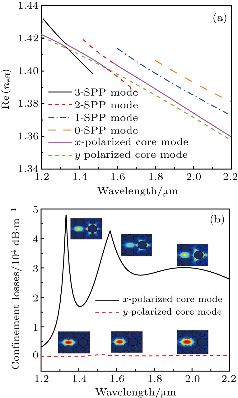
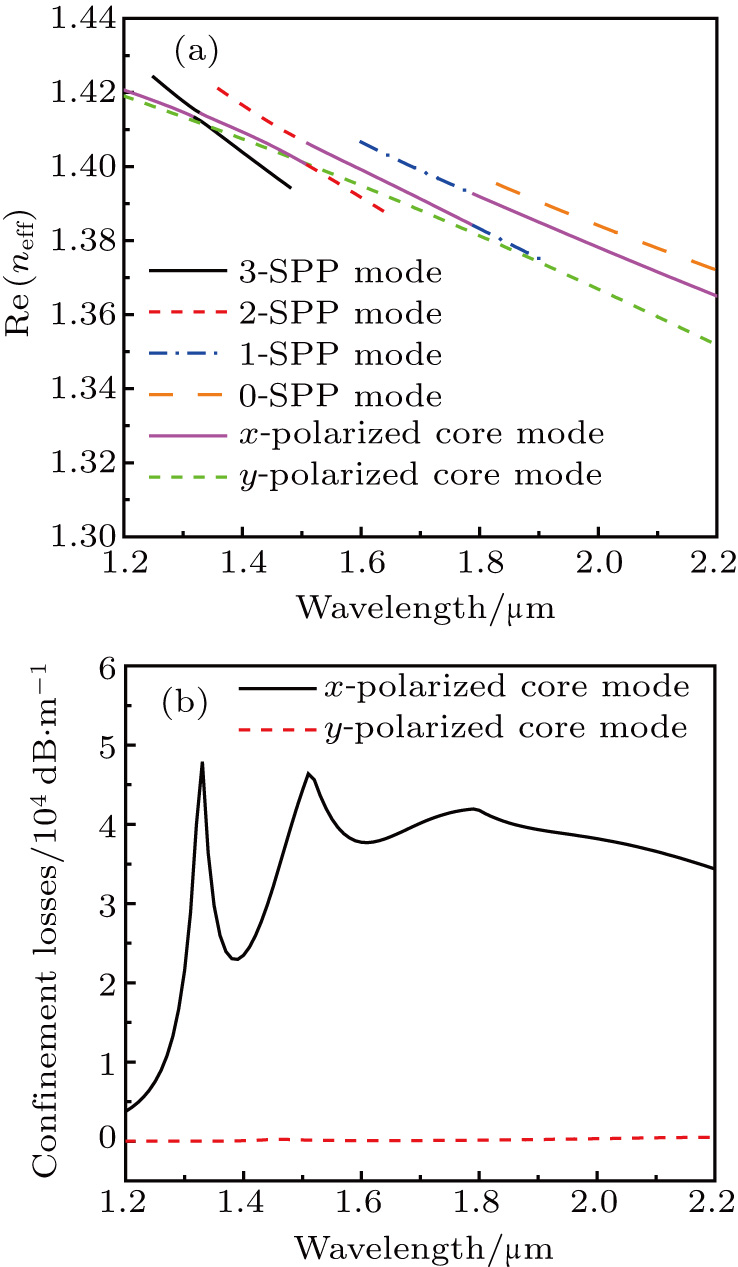
Figure
 | Fig. 2. (a) The real part of the effective refractive indices of the core modes and the x-polarized SPP modes, and (b) the confinement losses of the x- and y-polarized core modes. The insets showing the electric field distributions of the core modes at different wavelengths. |
In the following, some geometric parameters of PCF including d, d1, d2, Λx, and t are adjusted in order to investigate the coupling characteristic. The variations of the confinement loss of the x- and y-polarized with different d are shown in Figs.
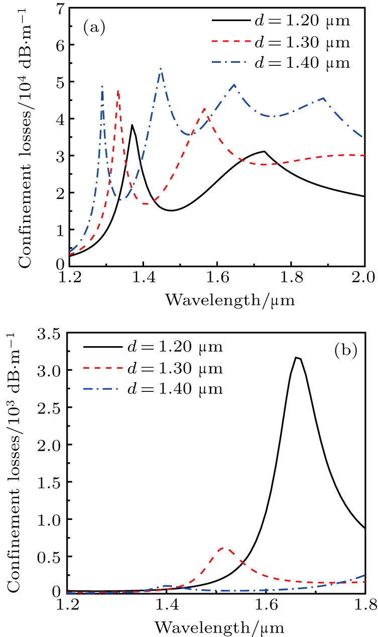 | Fig. 3. The variations of the confinement loss of (a) the x-polarized core mode and (b) the y-polarized core mode with different d. |
The variations of the confinement loss of the x- and y-polarized core modes with different values of d1 are shown in Figs.
 | Fig. 4. The variations of the confinement loss of (a) the x-polarized core mode and (b) the y-polarized core mode with different d1. |
The variations of the confinement loss of the x- and y-polarized core modes with different values of d2 are shown in Figs.
 | Fig. 5. The variations of the confinement loss of (a) the x-polarized core mode and (b) the y-polarized core mode with different d2. |
The variations of the confinement loss of the x- and y-polarized core modes with different values of Λx are shown in Figs.
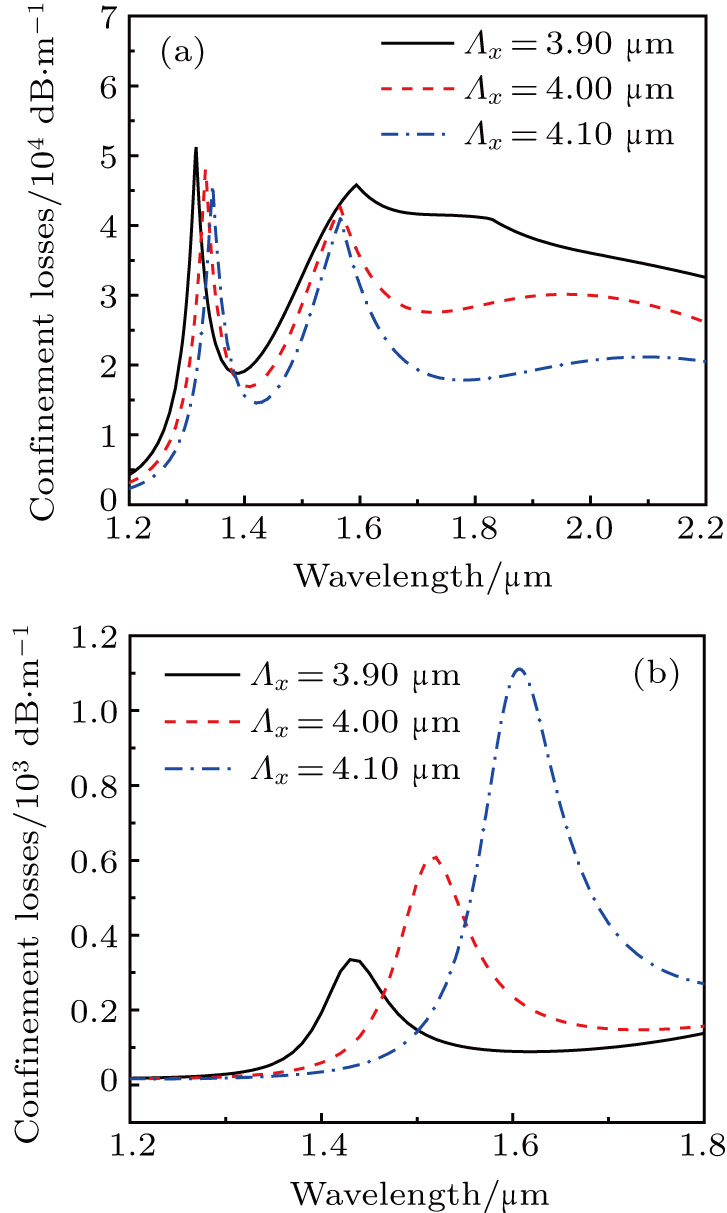 | Fig. 6. The variations of the confinement loss of (a) the x-polarized core mode and (b) the y-polarized core mode for different Λx. |
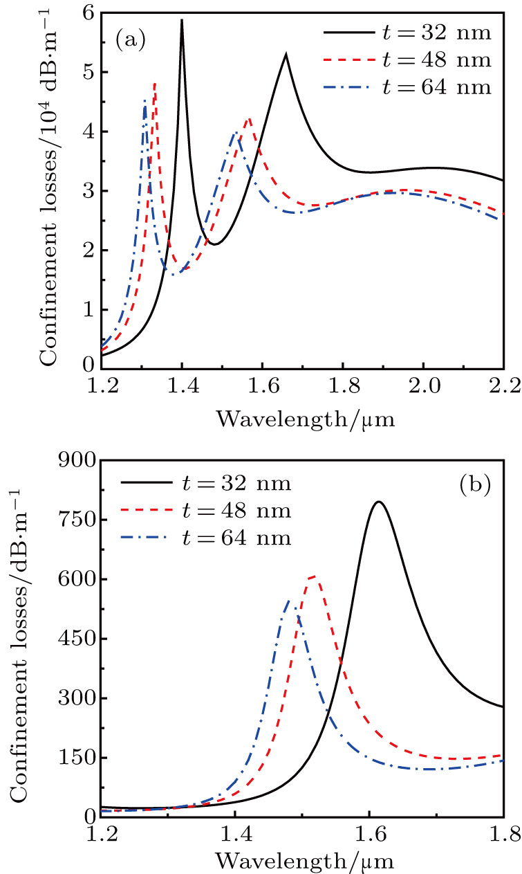
The variations of the confinement loss of the x- and y-polarized core modes with different values of t are shown in Figs.
 | Fig. 7. The variations of the confinement loss of (a) the x-polarized core mode and (b) the y-polarized core mode for different t. |
A broadband PCF polarization filter could be achieved by optimizing the fiber geometric parameters. Figure
 | Fig. 8. (a) The real part of the effective refractive indices of the x- and y-polarized core modes and SPP modes, and (b) the confinement losses of the x- and y-polarized core modes. |
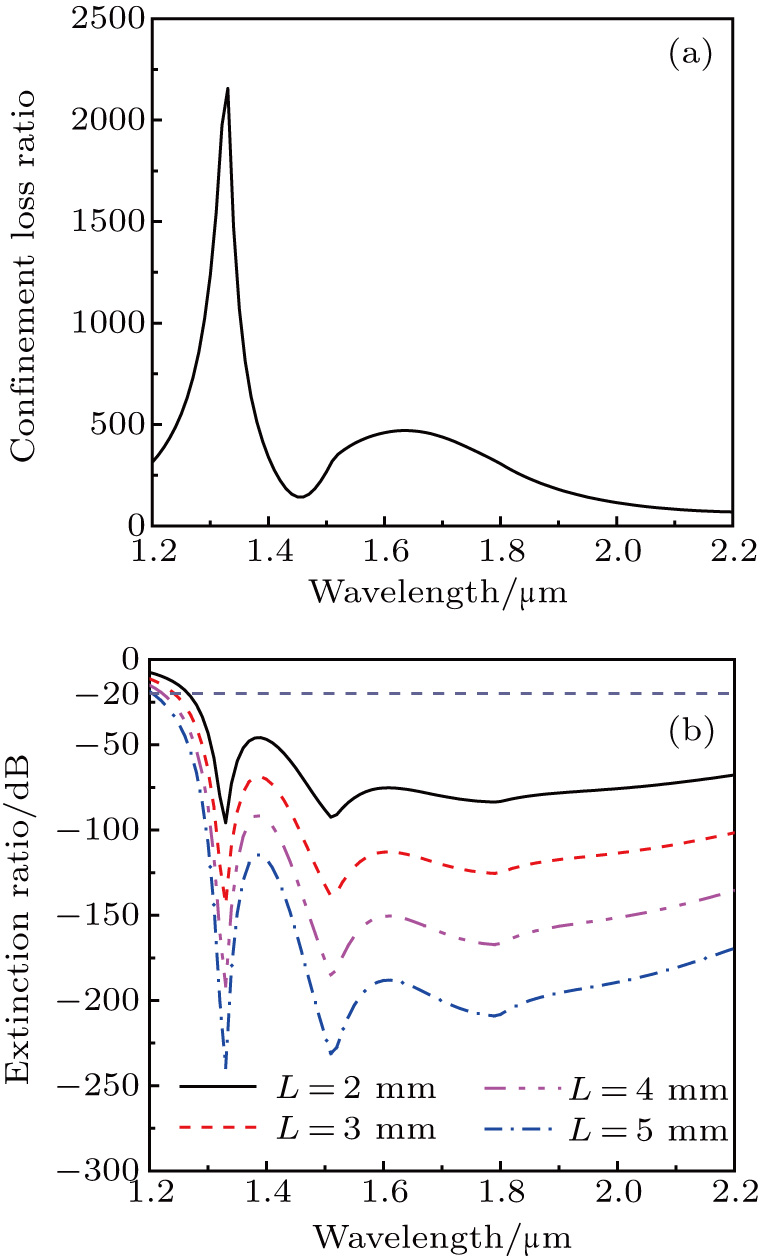
The confinement loss ratio, which is defined as the ratio of the confinement loss of the x-polarized core mode to the confinement loss of the y-polarized core mode, is used to evaluate the performance of the PCF polarization filter. Figure
 | Fig. 9. (a) The confinement loss ratio of the x-polarized core mode to the y-polarized core mode. (b) The variations of the ER with different L. |
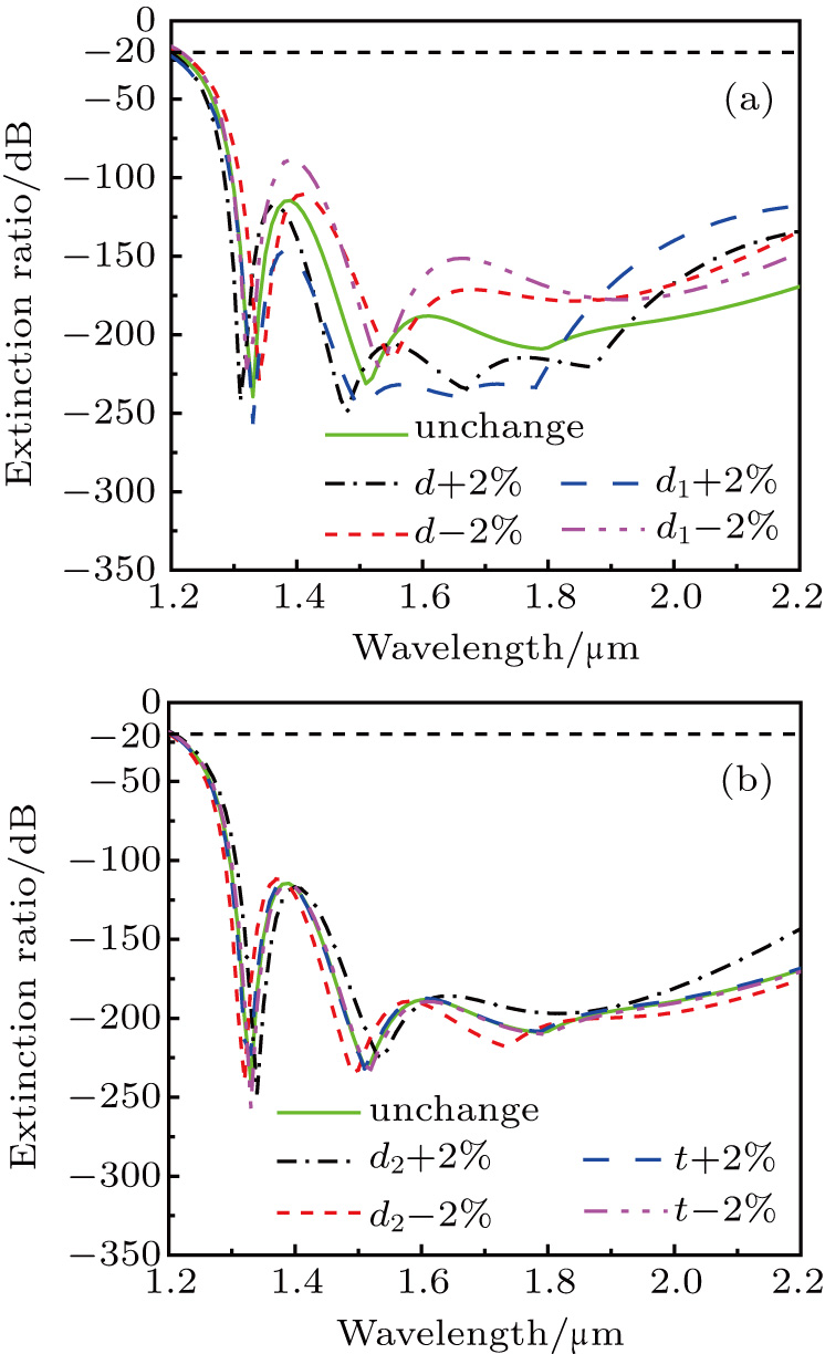
The PCF could be fabricated by some existing methods, such as stack and draw method, ultrasonic drilling, extrusion and surfacing.[33–35] Then the gold film can be plated in a pore by high pressure chemical vapor deposition method.[36] In the fabrication process, the error tolerances are analyzed. Figures
 | Fig. 10. The variations of the ER when (a) d, d1 and (b) d2, t have deviations of ±2%. |
4. Single wavelength PCF polarization filter
When the fiber geometric parameters are chosen as follows: d = 1.36 μm, d1 = 2.35 μm, d2 = 1.99 μm, Λx = 4.0 μm, and t = 42 nm, a single wavelength PCF polarization filter at wavelength 1.55 μm can be achieved. Figure
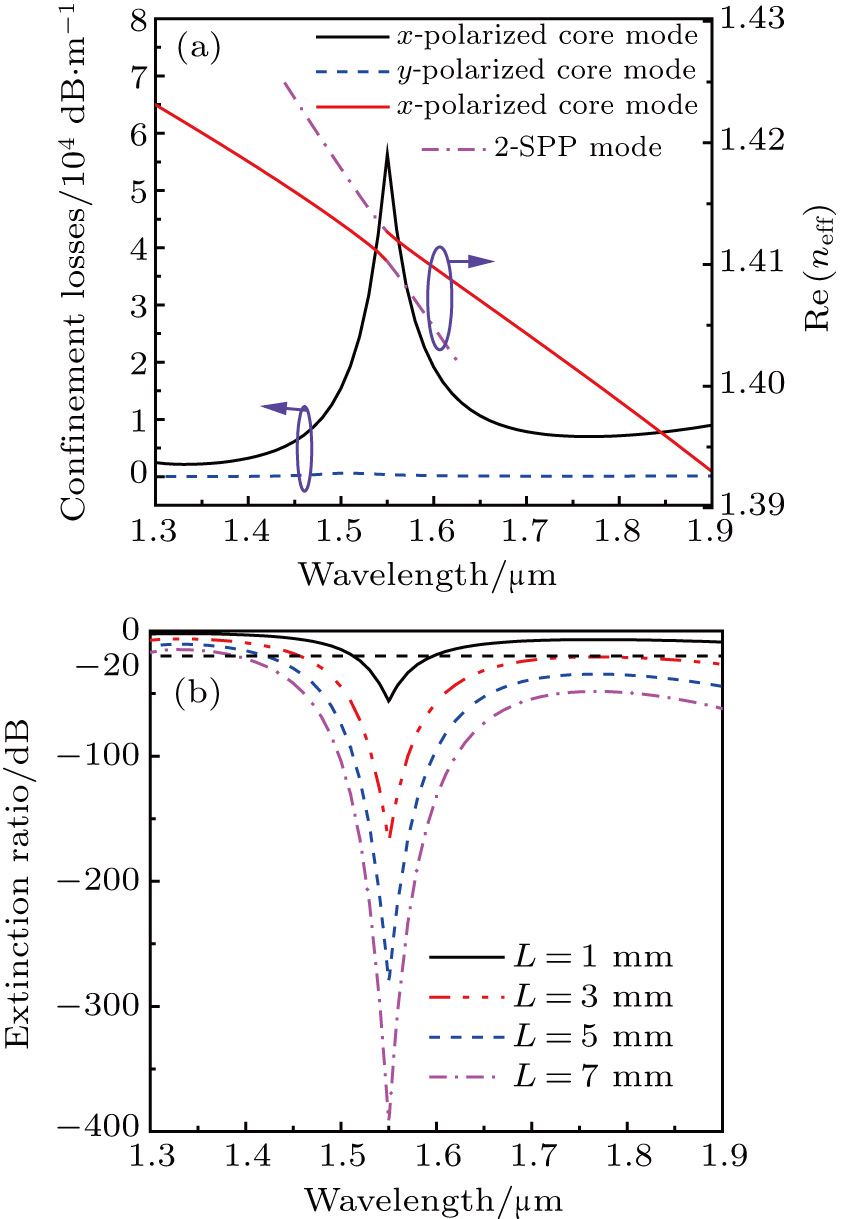 | Fig. 11. (a) The confinement losses of the x-polarized and y-polarized core modes and the real part of the effective refractive indices of the x-polarized core mode and 2nd-order SPP mode. (b) The variations of ER with different L. |
5. Conclusion
In summary, a plasmonic polarization filter based on the diamond-shape PCF is proposed. By optimizing the fiber geometric parameters, the polarization filter has a bandwidth of 990 nm and an ER of lower than −20 dB. Moreover, a single wavelength PCF polarization filter at wavelength 1.55 μm can be obtained. The confinement loss of the x-polarized core mode can be up to 56329.4 dB/m at wavelength 1.55 μm, where the confinement loss of the y-polarized core mode is only 374.6 dB/m. The proposed polarization filter has the advantages of large bandwidth, high ER, and short length, so it can be widely used in the laser and optical communication systems.
Reference
| [1] | |
| [2] | |
| [3] | |
| [4] | |
| [5] | |
| [6] | |
| [7] | |
| [8] | |
| [9] | |
| [10] | |
| [11] | |
| [12] | |
| [13] | |
| [14] | |
| [15] | |
| [16] | |
| [17] | |
| [18] | |
| [19] | |
| [20] | |
| [21] | |
| [22] | |
| [23] | |
| [24] | |
| [25] | |
| [26] | |
| [27] | |
| [28] | |
| [29] | |
| [30] | |
| [31] | |
| [32] | |
| [33] | |
| [34] | |
| [35] | |
| [36] |