Project supported by the National Natural Science Foundation of China (Grant Nos. 61601355 and 61571355), the China Postdoctoral Science Foundation (Grant No. 2016M602770), the Natural Science Foundation of Shaanxi Province, China (Grant Nos. 2018JM6018 and 2019JQ-405), the Postdoctoral Science Foundation of Shaanxi Province, China, and the Fundamental Research Funds for the Central Universities, China.
Abstract
Propagation dynamics of the cosh-Airy vortex (CAiV) beams in a chiral medium is investigated analytically with Huygens–Fresnel diffraction integral formula. The results show that the CAiV beams are split into the left circularly polarized vortex (LCPV) beams and the right circularly polarized vortex (RCPV) beams with different propagation trajectories in the chiral medium. We mainly investigate the effect of the cosh parameter on the propagation process of the CAiV beams. The propagation characteristics, including intensity distribution, propagation trajectory, peak intensity, main lobe’s intensity, Poynting vector, and angular momentum are discussed in detail. We find that the cosh parameter affects the intensity distribution of the CAiV beams but not its propagation trajectory. As the cosh parameter increases, the distribution areas of the LCPV and RCPV beams become wider, and the side lobe’s intensity and peak intensity become larger. Besides, the main lobe’s intensity of the LCPV and RCPV beams increase with the increase of the cosh parameter at a farther propagation distance, which is confirmed by the variation trend of the Poynting vector. It is significant that we can vary the cosh parameter to control the intensity distribution, main lobe’s intensity, and peak intensity of the CAiV beams without changing the propagation trajectory. Our results may provide some support for applications of the CAiV beams in optical micromanipulation.
The Airy packet is a solution of Schrödinger equation for a free particle.[1] Since the Airy beams with finite energy were introduced theoretically and generated experimentally by Siviloglou and Christodoulides in 2007,[2,3] the Airy beams have been extensively studied due to their intriguing properties, including nondiffracting,[4] self-healing,[5] and self-accelerating[2,3] properties. To date, applications of the Airy beams have been explored in optical trapping,[6] curved plasma channel generation,[7,8] and light bullet generation.[9,10] The optical vortex also has some interesting characteristics, such as phase singularity, autofocusing properties, and vector structure,[11] which have been used in optical communication[12] and optical micromanipulation.[13] Recently, the propagation dynamics of an optical vortex superimposed on Airy beams has become a research hotspot. Mazilu et al. have introduced the accelerating vortices embedded in Airy beams by employing a spiral phase on a cubic phase pattern.[14] Dai et al. theoretically and experimentally studied the propagation dynamics of Airy beams carrying phase singularity.[15,16] Subsequently, the propagations of Airy vortex beams in uniaxial crystals,[17–20] chiral medium,[21] gradient-index media,[22] turbulence atmosphere,[23] and nonlocal nonlinear medium[24] have been studied.
The chiral medium has broad applications in the non-linear optics field due to its structure and optical properties.[25] In nature, many materials can be considered as chiral media, such as human tissue, medicinal materials, and certain types of terrestrial vegetation layers.[26] Moreover, owing to the optical activity, when a linearly polarized vortex beam is incident on a chiral medium, it will be split into an LCPV beam and an RCPV beam, which have different phase velocities and propagation trajectories in a chiral medium.[27] Recently, the propagations of various beams in a chiral medium have been investigated, such as vortex Airy beam,[21] first-order chirped Airy vortex beam,[28] Bessel–Gaussian beam,[29] Airy–Gaussian vortex beam,[30] cos-Airy–Gaussian beam,[31] and chirped Airy–Gaussian vortex beam.[32] In this paper, we study the paraxial propagation of the CAiV beams in a chiral medium.
The CAiV beams can be deemed as a superposition of two Airy vortex beams with different decay factors and can be generated by using spatial light modulation.[33–35] Though the propagation properties of cosh-Airy beams are similar to those of the Airy beams, they possess more manipulation degrees of freedom than the corresponding Airy beams.[36] The self-healing property of cosh-Airy beam partially blocked by a finite opaque obstacle is better than that of the corresponding Airy beam.[37] In a word, the properties of the cosh-Airy beam are richer than those of the corresponding Airy beam. The beam propagation factor of a cosh-Airy beam was studied to evaluate the quality of the beam.[38] The periodic phase transition of the cosh-Airy beam was shown in a quadratic-index inhomogeneous medium.[39] The propagation of cosh-Airy beams in free space and uniaxial crystal orthogonal to the optical axis has been investigated.[36,40] But there has been no report on the propagation of the CAiV beams in a chiral medium so far. The investigation in the propagation of CAiV beams in a chiral medium is conducive to understanding the interaction mechanism of CAiV beams with a chiral medium. In the rest of the present paper, we mainly investigate the influence of the cosh parameter on the paraxial propagation of the CAiV beams in a chiral medium.
The rest of this paper is organized as follows. In Section 2, the analytical propagation expression of the CAiV beam through a chiral medium is obtained by the Huygens diffraction integral formula. In Section 3, the effect of the cosh parameter on different propagation properties of the CAiV beams is demonstrated. Finally, in Section 4, we draw some conclusions from this study.
2. The analytical expression for CAiV beams through chiral medium
In the Cartesian coordinate system, the z axis is assumed to be the propagation axis. At the initial plane, the electric field amplitude of an incident CAiV beam in the coordinate system can be described as follows:[36,39]
where A0 is the amplitude of the CAiV beam, a denotes the exponential decay factor varying from 0 to 1 to ensure the finite power of the CAiV beam, b is the parameter associated with the cosh function, w1 represents the beam width of the CAiV beam, w2 is the transverse scale associated with the cosh function, xd and yd separately refer to the dislocation of the optical vortex from the origin in the x and y axes, l is the topological charge, (Ai⋅) is the Airy function, and cosh(⋅) is the cosh function. The cosh function can be represented in the following form:
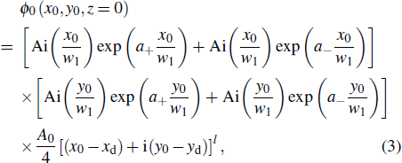
Substituting Eq. (2) into Eq. (1), we obtain the electric field amplitude of the CAiV beams at the initial plane as follows:
where a± = a ± a′ and a′ = bw1/w2, with a′ being the cosh parameter. Hence, the CAiV beams can be deemed as a superposition of two Airy vortex beams, which have different exponential decay factors. Since a± = a′ ± a′ must be positive, the cosh parameter a′ should be less than the decay factor a.
With the Huygens–Fresnel diffraction integral formula, the propagation of the CAiV beams through an optical ABCD system under the paraxial approximation can be determined as follows:[41]
where A, B, C, and D are the elements of the transfer matrix in a chiral medium. k = 2π/λ denotes the wave number, with λ being the wavelength of the beams in free space. Substituting Eq. (3) into Eq. (4), we obtain the electric field amplitude of the CAiV beams after propagating a distance z away as follows:[28,39]
in which Ai′(⋅) denotes the derivative of Airy function, and s = x or y.
Then, the ABCD transfer matrix of the optical system in the chiral medium can be described as
where the subscripts L and R denote the LCPV and RCPV beams, respectively, n(L) = n0/(1 + n0kγ) and n(R) = n0 (1 – n0kγ) respectively represent the refractive indices of the LCPV and RCPV beams, n0 is the original refractive index of the chiral medium, and γ is the chiral parameter. Substituting Eq. (11) into Eq. (5), we obtain the electric field amplitude of the LCPV beams to be ϕ(L)(x,y,z) and that of RCPV beams to be ϕ(R)(x,y,z) in the chiral medium. The electric field distribution of the LCPV and RCPV beams can be expressed as
Thus, the total electric field can be written as
The total intensity of the CAiV beams propagating in the chiral medium can thus be expressed as
with
3. Numerical calculations and analyses
With the analytical expression of the electric field, we further investigate the propagation properties of the CAiV beams through a chiral medium, with parameters chosen to be A0 = 1, a = 0.1, w1 = w2 = 0.1mm, xd = yd = − 0.3 mm, l = 1, λ = 633 nm, and n0 = 3. is the Rayleigh range.
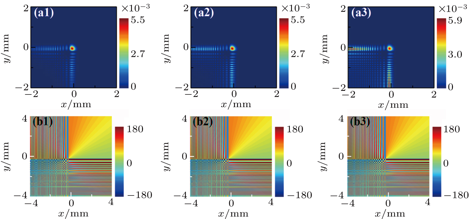
In Fig. 1, the intensity and phase distributions of the CAiV beams with different cosh parameters are simulated at the initial plane. When a′ = 0, the CAiV beam decreases to the Airy vortex beam. According to Figs. 1(a1)–1(a3), we can find that the intensity of the side lobes of the incident beams strengthens with the increase of the cosh parameters, so the CAiV beam has a bigger side lobe’s intensity than the corresponding Airy vortex beam. Furthermore, there are no distinct changes of the phase distributions with the modulation of the cosh parameters as shown in Figs. 1(b1)–1(b3). Therefore, the cosh parameters have a great influence on the intensity distributions of the CAiV beams but barely on their initial phase distributions.
Fig. 1. (a1)–(a3) Intensity distributions and (b1)–(b3) corresponding phase distributions of the CAiV beams at the initial plane z = 0, a′ = 0, 0.05, and 0.08, respectively.
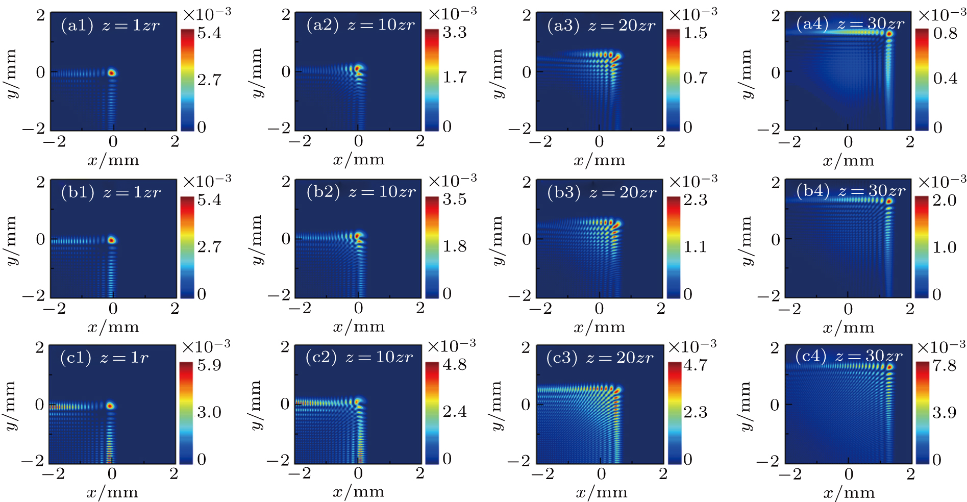
Figures 2 and 3 show the intensity distributions of the LCPV and RCPV beams with different cosh parameters at different propagation distances. It is obvious that the cosh parameters have a significant influence on the intensity distributions of the CAiV beams. Figures 2(a1)–2(a4) and 3(a1)–3(a4) show the evolutions of the LCPV and RCPV of Airy beams propagating through a chiral medium respectively. As we can see, the main lobe of the Airy vortex beam moves along a parabolic trajectory, and the intensity of the main lobe becomes weak with the increase of the propagation distance. Moreover, the acceleration of the LCPV beams is much bigger than that of the RCPV beams propagating through the chiral medium. The evolution characteristics of CAiV beams are similar to those of the Airy vortex beams \baselineskip=14.3pt plus.2pt minus.2pt in a chiral medium. Making a comparison among the first–third rows in Fig. 2, one can see that as the cosh parameters increase, the distribution areas of the LCPV beams become wider and the intensity of the side lobe becomes larger. At a shorter propagation distance (1zr), the increasing side lobes mainly concentrate at the position away from the main lobe.
Fig. 3. Transverse intensity distributions at different propagation distances for the RCPV beams with a′ = 0 [(a1)–(a4)], a′ = 0.05 [(b1)–(b4)], a′ = 0.08 [(c1)–(c4)], and γ = 0.16/k.
While, at the farther propagation distance (30zr), the increasing side lobes are mainly distributed in the neighborhood of the main lobe. Furthermore, the intensity of the LCPV beams becomes more evenly distributed with the cosh parameters increasing. Similarly, from Fig. 3, it is easy to find that the effect of the cosh parameter on the intensity distributions of the RCPV beams is the same as that of the LCPV beams. However, the evolution speed of the RCPV beams is much slower than that of the LCPV beams. Compared with the Airy vortex beam, the CAiV beam has very uniform and wide intensity distribution.
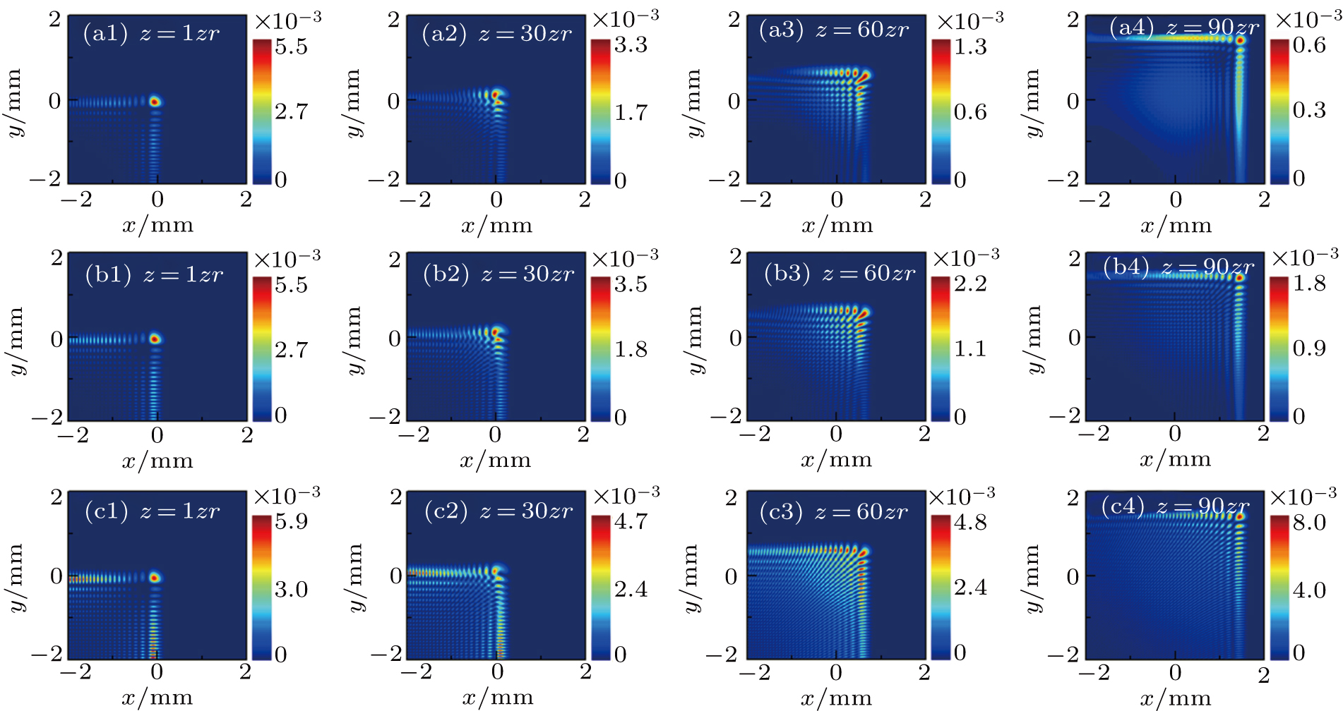
Following Figs. 2 and 3, we numerically simulate the propagations of the total beams with different cosh parameters in the chiral medium as shown in Fig. 4. From Figs. 4(a1)–4(c1) and Figs. 4(a2)–4(c2), it is not difficult to find that the intensity patterns of the total beams are similar to the patterns of the LCPV and RCPV beams at a shorter propagation distance. With the increase of the propagation distance, the intensity pattern of the total beams will be gradually split into two Airy-like patterns due to the relative speed between the LCPV beams and the RCPV beams, which is shown in Figs. 4(a3)–4(c3) and Figs. 4(a4)–4(c4). Comparing Figs. 4(a3)–4(a4) with Figs. 4(c3)–4(c4), we can find that the larger the value of a′, the larger the intensity of the total beams will be. The total intensity of the CAiV beam is larger than that of the corresponding Airy vortex beam.
Fig. 4. Transverse intensity distributions at different propagation distances for the total beams with a′ = 0 [(a1)–(a4)], a′ = 0.05 [(b1)–(b4)], a′ = 0.08 [(c1)–(c4)], and γ = 0.16/k.
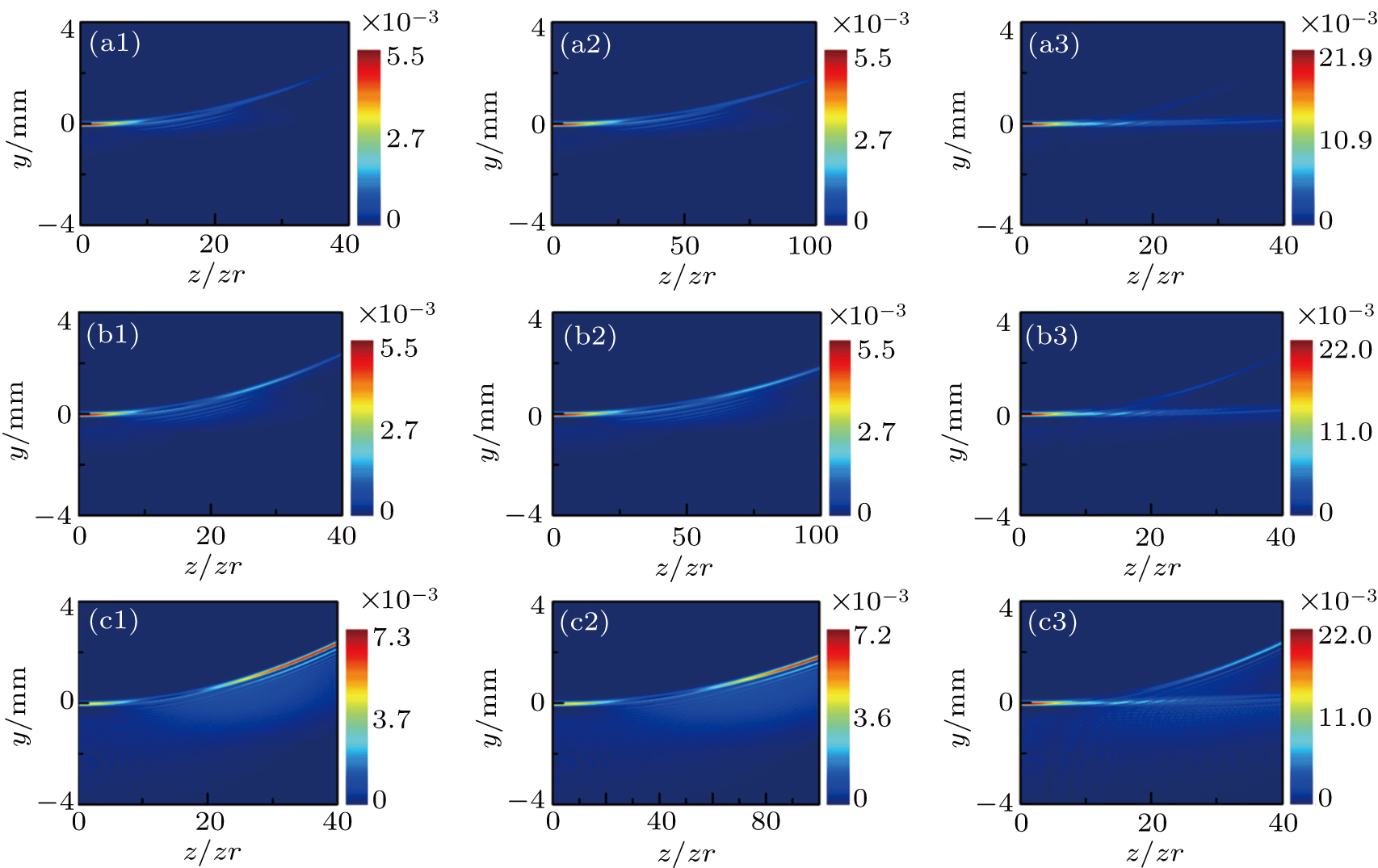
The propagation trajectories of the LCPV beams, RCPV beams, and total beams with different cosh parameters are presented in Fig. 5. As we can see, the propagation trajectories of the LCPV beams, RCPV beams and total beams are apparently different. A comparison between Figs. 5(a1)–5(c1) and Figs. 5(a2)–5(c2) shows that the acceleration of the LCPV beams is much bigger than that of the RCPV beams. Making a comparison among the first–third rows in Fig. 5, we can find that with the cosh parameters increasing, the side-view intensities of the LCPV beams, RCPV beams and total beams are strengthened significantly at a farther propagation distance. While the cosh parameters will not affect the propagation trajectory of the CAiV beams.
Fig. 5. Side-view intensity pattern of the LCPV beams, RCPV beams, and total beams with different cosh parameters, respectively, for a′ = 0 [(a1)–(a3)], a′ = 0.05 [(b1)–(b3)], a′ = 0.08 [(c1)–(c3)], and γ = 0.16/k.
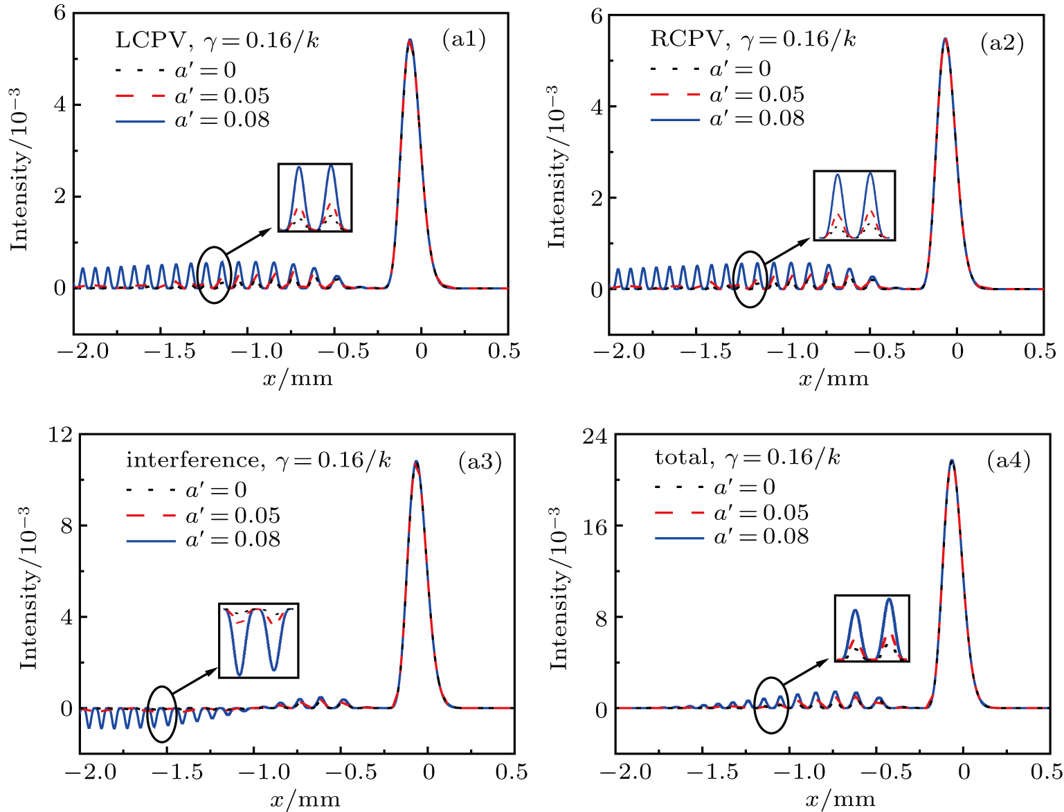
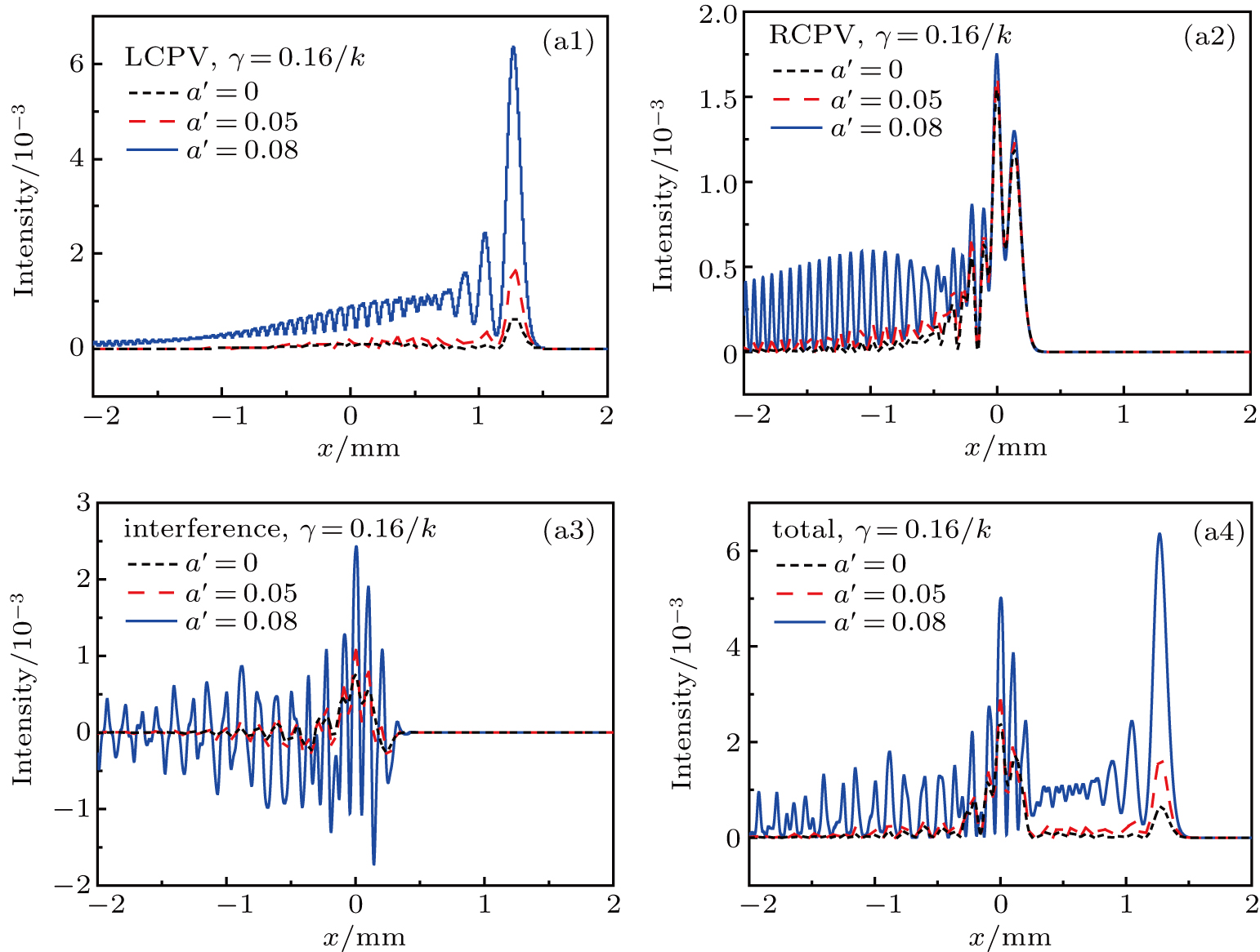
In order to further analyze the influence of the cosh parameters on the evolution characteristics of the CAiV beams, in Figs. 6 and 7, we show the intensity distributions of the CAiV beams varying with x in near and far-field space respectively. In Figs. 6(a1),6(a2), and 6(a4), in the near-field space, one can see that with the increase of the cosh parameter a′, the side lobe’s intensities of the LCPV beams, RCPV beams and total beams will strengthen, while the main lobe’s intensity of the beams will not change. On the contrary, in the far-field space, when the cosh parameter a′ increases, both the main lobe’s intensity and side lobe’s intensity of the LCPV beams, RCPV beams, and total beams will become larger as displayed in Figs. 7(a1),7(a2), and 7(a4). Moreover, the intensity of the CAiV beams increases more in the far-field than that in the near-field as the cosh parameters increases. In Fig. 6(a3), in the near-field, the value of the negative intensity of the interference term will increase with the cosh parameter increasing. However, in the far-field, both the positive and negative intensity of the interference term will increase with the increase of the cosh parameter as depicted in Fig. 7(a3). The interference effect is more significant in the far-field than that in the near-field.
Fig. 6. Intensity distributions of (a1) LCPV beams, (a2) RCPV beams, (a3) interference term, and (a4) total beams varying with x for different cosh parameters propagating in chiral medium in near-field space for z = 1zr.
Fig. 7. Intensity distributions of (a1) LCPV beams, (a2) RCPV beams, (a3) interference term, and (a4) total beams varying with x for different cosh parameters propagating in chiral medium in far-field for z = 30zr.
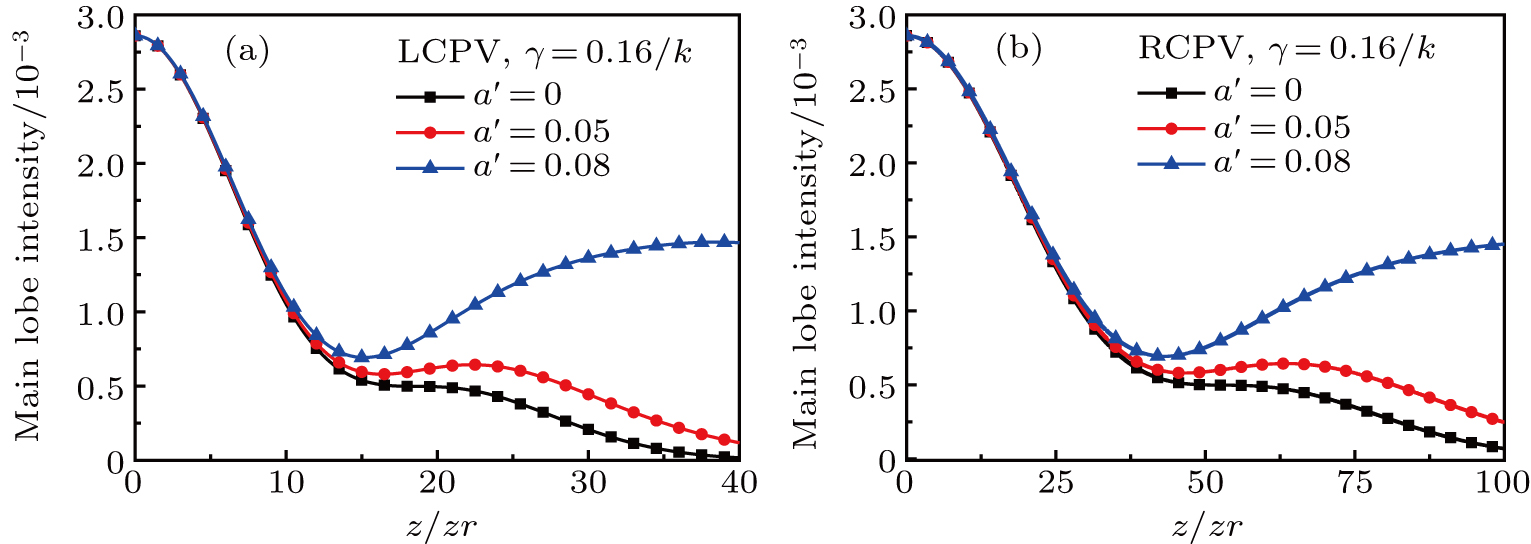
Figure 8 shows the plots of the main lobe’s intensity distributions of the LCPV and RCPV beams for different cosh parameters at different propagation distances, respectively. From Figs. 8(a) and 8(b), we can see that the cosh parameter has the same influence on the main lobe’s intensity distributions of the LCPV and RCPV beams. For the LCPV beams, when the propagation distance is less than 10zr, the cosh parameters will not affect the main lobe’s intensity distribution. While, when the propagation distance is greater than 10zr, the main lobe’s intensity of the LCPV beams will increase with the cosh parameter increasing. In addition, we find that when a′ = 0, for the Airy vortex beam, the main lobe’s intensity of the LCPV and RCPV beams will gradually decrease with the increase of the propagation distance. However, when a′ = 0.08, for the CAiV beam, the main lobe’s intensities of the two beams initially decrease and then increase with the propagation distances increasing. So we can control the main lobe’s intensity of the CAiV beams by changing the cosh parameter a′.
Fig. 8. Main lobe’s intensity distributions of (a) LCPV beams and (b) RCPV beams for different cosh parameters propagating in chiral medium.
The peak intensity distributions of the LCPV beams, RCPV beams, and total beams with different cosh parameters at different propagation distances are presented in Fig. 9. Here the peak intensity is the maximum value of the intensity in the transverse intensity pattern. From Figs. 9(a)–9(c), it is not difficult to find that the cosh parameter has the same influence on each of the peak intensity distributions of the LCPV beams, RCPV beams, and total beams. As the cosh parameter increases, the peak intensity of the CAiV beams increases. For a′ = 0.08, the maximum of the peak intensity of the LCPV beams appears at the farther propagation distance z = 30zr. While the maximum of the peak intensity of the RCPV beams and that of total beams are located at the initial position. Owing to the cosh parameter, the peak intensity of the CAiV beam is larger than that of the corresponding Airy vortex beam.
Fig. 9. Peak intensity distributions of (a) LCPV beams, (b) RCPV beams, and (c) total beams for different cosh parameters propagating in chiral medium.
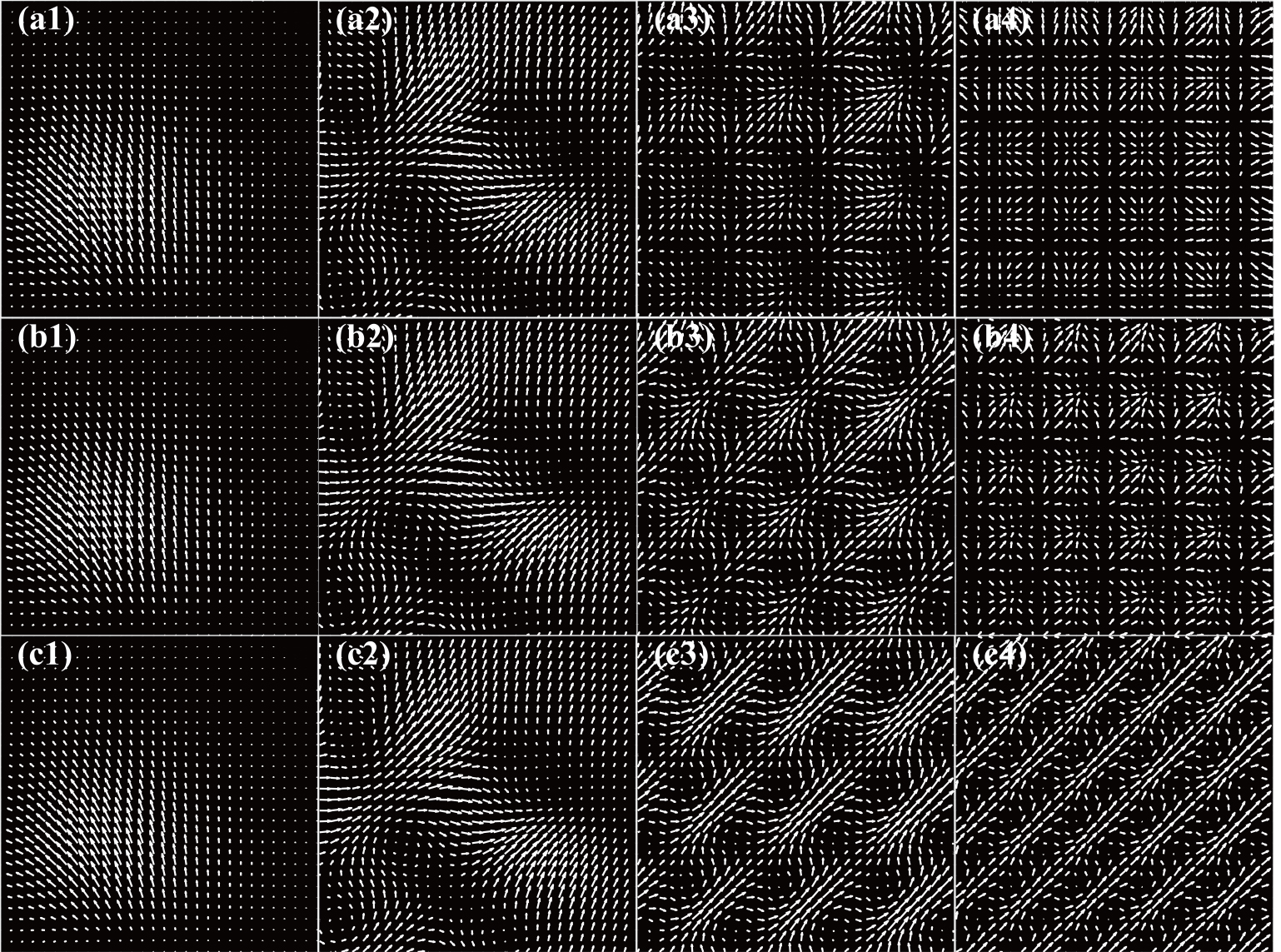
Finally, we study the Poynting vector and angular momentum of the CAiV beams through the chiral medium with different cosh parameters. The Poynting vector is the rate of electromagnetic energy flow per unit area, which is defined as s = (c/4π)E × B,[42] where c is the speed of light, E and B are the electric and magnetic field, respectively. In the Lorenz gauge, the time-averaged Poynting vector of an -polarized field can be written as[43,44]
where
ex, ey, and ez are the unit vectors in the x, y, and z directions, respectively, and ω is the angular frequency. From Eq. (16), it is not difficult to find that the energy flow in the z direction is proportional to the light intensity, which can be influenced by the cosh parameter serving as the intensity distribution. Because the variation trend of the transverse Poynting vector for the LCPV beams is similar to that of the RCPV beams, we mainly discuss the effect of the cosh parameter on the transverse Poynting vector of the LCPV beams. As shown in Fig. 10, we numerically simulate the transverse Poynting vector of the LCPV beams with different cosh parameters at different propagation distances. From Figs. 10(a3)–10(c3) and Figs. 10(a4)–10(c4), we can see that as the cosh parameters increase, the higher transverse energy flow moves along the direction of the main Airy peak (45°), which verifies the increase of main lobe’s intensity with the cosh parameter increasing at a farther propagation distance for the CAiV beam.
Fig. 10. Transverse Poynting vector of the LCPV beams propagating in the chiral medium at the positions: z = 1zr [(a1)–(c1)], 10zr [(a2)–(c2)], 20zr [(a3)–(c3)], 30zr [(a4)–(c4)], for a′ = 0 [(a1)–(a4)], a′ = 0.05 [(b1)–(b4)], a′ = 0.08 [(c1)–(c4)], and γ = 0.16/k.
As is well known, 〈J〉 = r × 〈E × B〉, from which it follows that the time-averaged angular momentum density in the ez is[45,46]
where
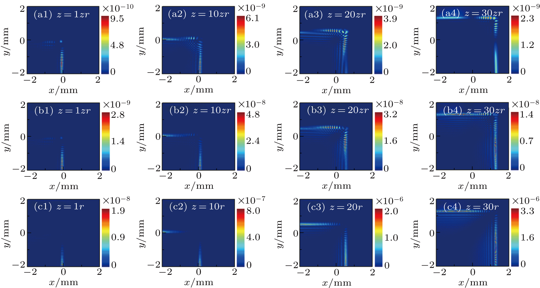
Figure 11 shows the longitudinal angular momentum densities of the LCPV beams with different cosh parameters at different propagation distances in a chiral medium. A comparison among the first–third rows in Fig. 11 shows that as the cosh parameter increases, the angular momentum density of the main lobe disappears, and the angular momentum density gradually concentrates to the side lobe. Moreover, the value of the angular momentum density of the LCPV beams will become greater with the increase of cosh parameters.
Fig. 11. Longitudinal angular momentum densities at different propagation distances for the LCPV beams with a′ = 0 [(a1)–(a4)], a′ = 0.05 [(b1)–(b4)], a′ = 0.08 [(c1)–(c4)], and γ = 0.16/k.
4. Conclusions
In this paper, the propagation of the CAiV beams in a chiral medium is investigated. We numerically simulate the intensity distribution, propagation trajectory, peak intensity, main lobe’s intensity, Poynting vector, and angular momentum of the CAiV beams with different cosh parameters in a chiral medium. Our results show that the cosh parameters have the same effect on the intensity distribution of the LCPV and RCPV beams. As the cosh parameters increase, the distribution areas of the LCPV and RCPV beams become wider, and the side lobe’s intensity and peak intensity become larger. While, the cosh parameters will not affect the propagation trajectory of the LCPV beams nor RCPV beams. By introducing the cosh parameter, the side lobe’s intensity of the Airy vortex beams increases, which improves the trapping capability of the Airy vortex beams at the side lobes significantly. Moreover, as the cosh parameter increases, the main lobe’s intensity of the LCPV and RCPV beams increase at a farther propagation distance. Therefore, without the propagation trajectory changed, one can adjust the cosh parameters to control intensity distribution, the main lobe’s intensity, and peak intensity of the CAiV beams in the chiral medium to meet the actual usage. Finally, the Poynting vector and angular momentum of the CAiV beams through the chiral medium with different cosh parameters are discussed. We find that higher transverse energy flow moves along the direction of the main Airy peak for the CAiV beams with the increase of cosh parameters. We believe that our investigation is valuable for fully exploring the possibility and functionality of the CAiV beams in optical manipulation.