Characteristics of urea under high pressure and high temperature
Fang Shuai, Ma Hong-An, Guo Long-Suo, Chen Liang-Chao, Wang Yao, Ding Lu-Yao, Cai Zheng-Hao, Wang Jian, Jia Xiao-Peng
State Key Laboratory of Superhard Materials, Jilin University, Changchun 130012, China


† Corresponding author. E-mail: maha@jlu.edu.cn jiaxp@jlu.edu.cn

Abstract

The properties of urea under high pressure and high temperature (HPHT) are studied using a China-type large volume cubic high-presentation apparatus (CHPA) (SPD-6 × 600). The samples are characterized by scanning electron microscopy (SEM), x-ray diffraction (XRD), and Raman spectroscopy. By directly observing the macroscopic morphology of urea with SEM, it is confirmed that the melting point of urea rises with the increase of pressure. The XRD patterns of urea residues derived under different pressures show that the thermal stability of urea also increases with the increase of pressure. The XRD pattern of the urea residue confirms the presence of C3H5N5O (ammeline) in the residue. A new peak emerges at 21.80°, which is different from any peak of all urea pyrolysis products under normal pressure. A more pronounced peak appears at 708 cm−1 in the Raman spectrum, which is produced by C–H off-plane bending. It is determined that the urea will produce a new substance with a C–H bond under HPHT, and the assessment of this substance requires further experiments.

1. Introduction

Urea is a simple organic compound and is the main nitrogen-containing end product of protein metabolism in mammals and certain fish.[1] The German chemist Friedrich Wöhler disproved the vitalistic theory by synthesizing urea in a lab. Today, urea is widely used as an industrial raw material, and its derivatives are used in fertilizers.[27] Urea is also a good organic catalyst,[1,3,4] and in recent years it has been used in the synthesis of mesoporous spinel NiCo2O4 nanostructures,[5] hierarchical BiVO4/Bi2O2CO3 nanocomposites with enhanced visible-light photocatalytic activity,[4] and nitrogen-doped graphene hydrogels.[8] The pyrolysis reaction of urea under normal pressure has been comprehensively studied, however, the characteristics of urea under high pressure have not yet been investigated. When the temperature reaches the decomposition point of urea, the urea will decompose to produce ammonia and cyanic acid, and the decomposition rate will increase with the increase of temperature. As the temperature in the reactor continues to rise, the cyanic acid reacts with the urea to form a biuret. The biuret will then react with the cyanic acid to produce cyanuric acid. The urea in the reactor will reacts with the pyrolysis product, and the pyrolysis products will also react with each other, which causes the pyrolysis reaction of urea to become particularly complicated.[9,10] Studying the properties of urea under high pressure and high temperature (HPHT) is also beneficial to expand the use of urea under high pressure conditions.

Urea is a ubiquitous organic matter composed of C, H, O, and N elements in the earth’s crust. The study of the characteristics of urea under high temperature and high pressure will also provide data support for researchers exploring forms of urea existing in the earth and its possible reactions. According to the earth science research, the pressure at 35 km below the surface is about 1.0 GPa.[1113] From this, it can be estimated that the deep pressure of the lithosphere is about 1.0 GPa. Thus, the pressure interval is determined to be between 0.3 GPa and 1.0 GPa according to the high temperature and high pressure measurement equipment.

In this paper, urea is studied under high temperature and high pressure. It is observed that the melting point and thermal stability of urea will increase with the increase of pressure. To a certain extent, this discovery explains the characteristic change of urea under high pressure, and provides data support for researchers to study the state of different organic compounds under HPHT. At the same time, urea exhibits different atmospheric pressure characteristics under HPHT, which is conducive for expanding its industrial use.

2. Experimental details

High temperature and high pressure testing of urea is carried out using a China-type large volume cubic high-pressure apparatus (CHPA) (SPD-6 × 600) in a pressure range of 0.3–1.0 GPa and a temperature range of 300–600 K. The experimental assembly is provided in Fig. 1. The sample is placed in the middle of the cavity to ensure that the temperature is uniform, and the urea is wrapped with a steel sleeve to facilitate the collection of residues. When the steel sleeve is removed, the molten urea leaks out of the cavity.

Fig. 1. Experimental schematic diagram; 1: conductive steel ring; 2: copper sheet; 3: graphite heater; 4: liner tube; 5: small plug; 6: urea; 7: insulator; 8: steel sleeve; 9: large plug; 10: pyrophyllite.

The purity of the urea used is 99.0 wt.%. Before testing, the urea is placed in an agate mortar for thorough grinding to ensure uniform particle size. This is advantageous for observing the change in morphology of the urea under SEM and determining if the urea melts.

The temperature measurement assembly of the experiment is illustrated in Fig. 2. The experimental chamber temperature is calibrated according to the relationship between the input power and the temperature measured by a K-type Ni-10%C and Ni-3%Si thermocouple. The diameter of the thermocouple is 0.2 mm.[1417] Due to the error of the thermocouple itself and other external conditions, the error caused by the uncertainty of the measured temperature is estimated to be 1%. The experimental synthesis pressure is based on the high pressure phase transition points of Bi, Ba, and Tl. This is to calibrate the corresponding relationship between the actual pressure inside the chamber and the CHPA oil pressure, obtaining the calibration curve. The calibration curve extends to the low pressure zone so that the corresponding oil pressure at lower pressures can be estimated. The accuracy of pressure calibration is estimated to be 5%.[1316,18,19]

Fig. 2. Schematic diagram of experimental temperature measurement; 1: conductive steel ring; 2: copper sheet; 3: graphite tube; 4: Ni-10%C; 5: small plug; 6: ceramic tube; 7: insulating tube; 8: liner tubeliner; 9: Ni-3%Si; 10: pyrophyllite; 11: large plug.

Once the experiment is complete, whether the urea has leaked is directly observed to determine the melting point of the urea. The morphology of the sample surface is observed using a scanning electron microscope (SEM), the residue of urea is analyzed by x-ray diffraction (XRD), and Raman spectroscopy is used to determine the product of urea at high temperature and high pressure.

3. Results and discussion
3.1. Macroscopic morphology of urea melting

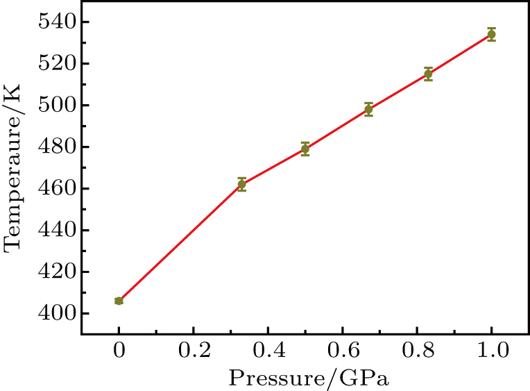
Urea is a molecular crystal with a melting point of 405.7 K under normal pressure.[16] Table 1 lists the melting and decomposition of urea under different pressures, showing the different characteristics compared to those under normal pressure.

Table 1.

Melting point experiment of urea under different temperature and pressure conditions.

.

The assembly diagram of the experiment is shown in Fig. 1. To more clearly observe the melting of urea, the steel sleeve illustrated in Fig. 1 is removed. This leaves a gap between the experimental assembly parts, so the molten urea can permeate out of the gap. This phenomenon can be exploited to determine the melting point of the urea as the melted urea cannot be measured in situ. In this paper, the temperature range of urea melting is reduced step by step. Due to the inevitable variability of each experiment, there is an error of ±3 K for the determination of the melting point at each pressure point.

Figure 3(a) and 3(c) are the optical photographs of the pyrophyllite blocks of R-9 and R-2, respectively, while figure 3(b) and 3(d) are the optical photographs of the corresponding urea residues. The pressure and temperature of the two sets of experiments are 0.5 GPa and 480 K, and the experimental time is 20 min and 40 min, respectively. The pyrophyllite block in Fig. 3 displays a large variation. When the experimental time is extended, the molten urea permeates out of the cavity and sticks to the pyrophyllite block. This shows that it takes time for the urea to melt from solid state to liquid in the cavity.

Fig. 3. (a) Pyrophyllite block of R-9; (b) urea residue of R-9 at 20 min; (c) pyrophyllite block of R-2; (d) urea residue of R-2 at 40 min. The pressure and temperature are 0.5 GPa and 480 K, respectively.

Once the the pyrophyllite is removed, the residue of urea in the reaction chamber can be observed. The urea residue in Fig. 3(b) is relatively complete, and there is a hole in the center of the urea sample, which is caused by urea decomposition. In Fig. 3(d), almost no urea residue is visible in the cavity, and the melted urea seeps out from the cavity and solidifies again on the surface of pyrophyllite.

Both R-3 and R-2 have the same pressure and only the experimental temperature is reduced, however, the urea cannot permeate from the cavity. Even when the experimental time is extended to 90 min, the urea does not flow out of the chamber. This proves that urea will only flow out of the chamber when the temperature reaches the melting point. If the melting point is not reached, even if the time is extended, the urea will not melt. According to these results, it can be determined that the melting point of urea is 480 K at the pressure of 0.5 GPa.

A temperature–pressure map is provided in Fig. 4 based on the data in Table 1. From Fig. 4, it can be concluded that when the pressure increases, the melting point of urea also increases. It can also be found that during the process of increasing the pressure from 0.33 GPa to 1.0 GPa, gas with a pungent taste is generated in the reaction chamber, indicating that the melting process of urea is accompanied by the decomposition of urea.

Fig. 4. The melting point temperature changes with pressure.
3.2. Microscopic morphology of urea residues

The melting point of urea can be determined by the phenomenon in which the urea permeates out of the cavity after melting. As the experimental chamber is sealed, the process of melting the urea in the chamber cannot be observed in real time. The experiment time is thus shortened in order to capture the urea in the middle of the melting process. The melting process of urea is then determined by observing its microscopic morphology.

A scanning electron micrograph of R-7 cold pressed urea is provided in Fig. 5(a). It can be observed from the figure that the urea sample has good density and there is no gap in the sample. Figure 5(b) is a scanning electron micrograph of the R-8 residual sample in which a large gap between the urea samples occurs, and there is a trace of melting and recrystallization on the surface. The large gap present in the sample is formed by the decomposition of urea under HPHT conditions that generates a large amount of gas. This phenomenon also confirms that under high pressure, urea will still decompose and generate a large amount of gas in the same way it would under normal pressure. The large pores fail to prove that the temperature had reached the melting point of urea. However, from the melting and recrystallization traces on the sample surface, it can be concluded that the sample did reach the melting point.

Fig. 5. SEM photos of urea under different pressure, temperature, and experimental time, respectively: (a) 0.33 GPa, 300 K, 20 min; (b) 0.33 GPa, 460 K, 20 min; (c) 0.33 GPa, 460 K, 40 min; (d) 0.5 GPa, 480 K, 20 min; (e) 0.67 GPa, 500 K, 20 min; (f) 0.83 GPa, 515 K, 20 min; (g) 1 GPa, 535 K, 20 min.

A scanning electron micrograph of the R-1 residual sample is provided in Fig. 5(c), in which the urea exhibits a completely melted and recrystallized morphology. Figure 5(d)5(g) are the SEM images of R-9, R-10, R-11, and R-12, respectively. A structure similar to that of Fig. 5(b) is observed in the scanning electron micrographs of the four sets of experiments. At the end of the experiment, the morphology of the urea residue in the reaction chamber is similar to that of R-8, and a pungent odor is also detected. It can be observed from the high-magnification SEM morphology of urea that the melting process is accompanied by a decomposition process. This phenomenon indicates that urea melting is accompanied by decomposition.

3.3. XRD determination of residual urea samples

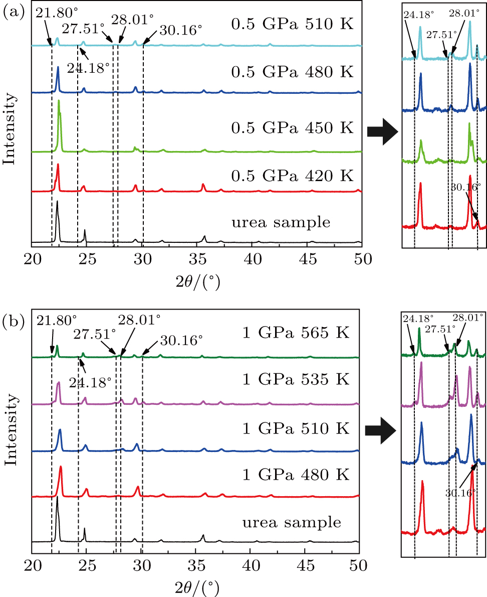
The XRD pattern of residual urea at different temperatures is shown in Fig. 6(a), at a pressure of 0.5 GPa. As the temperature in the chamber increases, the peak intensity of the XRD of the urea gradually decreases, and when the data under different conditions are put together, smaller peaks are concealed. Therefore, it is advantageous to observe the change of urea by amplifying the tiny peaks alone. When the temperature is 385 K, there is still only a peak of urea in the XRD pattern. The temperature of 385 K is already much higher than the decomposition temperature under normal pressure of urea, which proves that the increase in pressure inhibits the decomposition of urea and enhances its thermal stability. When the experimental temperature reaches 420 K, the XRD pattern of residual urea shows a peak at 30.16°. The cause of the peak cannot be determined with only one isolated peak, but its appearance proves that urea has started to undergo a chemical reaction at this temperature. In combination with the Raman spectrum in Fig. 8, no new peaks are generated at this temperature, so the cause of the 30.16° peak needs to be further determined. When the pressure increases, the thermal stability of the urea also increases. Combined with the microscopic topography of the urea sample in Fig. 5, as the temperature is increased to the melting point, the urea will generate gas and melt then permeate out of the chamber.

Fig. 6. XRD diagram of residual urea at different temperature and pressure.
Fig. 7. XRD analysis of urea residues.
Fig. 8. Raman spectra at different temperatures under 0.5 GPa.

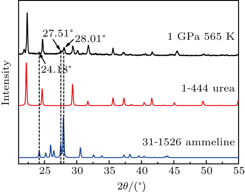
As shown in Fig. 6, at the pressure of 0.5 GPa, three peaks appear in the urea residue map when the temperature is raised to 480 K. The peaks are located at 28.01°, 27.51°, and 24.18°, respectively. The XRD analysis of the urea samples is provided in Fig. 7. The three peaks are determined to be peaks of C3H5N5O, which also appear in the pyrolysis of urea under normal pressure conditions. As the temperature further increases, the peaks of C3H5N5O remain. When the temperature is raised to 510 K, a new peak emerges at 21.80° which does not correspond to any peak of the pyrolysis product under normal pressure of urea. This is a product unique to high pressure and its chemical composition requires further analysis.

The XRD pattern of residual urea at different temperatures at a pressure of 1 GPa is illustrated in Fig. 6(b). Figure 6(b) and 6(a) show the same trend. When the pressure is raised to 1 GPa, the thermal stability of urea is further improved, confirming that the thermal stability of urea increases with rising pressure. When the temperature is raised from 510 K to 565 K, there will also appear peaks of C3H5N5O. The temperature required for urea to produce various products at a pressure of 1 GPa is higher than that at 0.5 GPa. The order of occurrence of various products under the pressures of 1 GPa and 0.5 GPa is fixed, indicating that the products produced by urea under high temperature and high pressure meet the specific generation rules.

3.4. Raman detection of residual urea samples

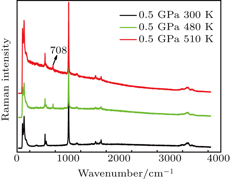
The Raman spectra of residual urea at different temperatures under the same pressure conditions are provided in Fig. 8. When the temperature is raised to 480 K, a more pronounced peak appears at the 708 cm−1 position, caused by C–H off-plane bending.[3,2023] This phenomenon indicates that a substance with C–H bond is formed in urea under HPHT conditions. This substance is not available under normal pressure, and corresponds to the new peak at 21.80° in the XRD pattern. As the temperature is increased further, the peak appearing at the 708 cm−1 position remains. The same phenomenon occurs when the pressure is raised to 1 GPa. Combining the results of XRD and Raman testing, it can be concluded that urea will produce a new substance with C–H bond under high temperature and high pressure, and the verification of this substance requires further investigation.

4. Conclusion and perspectives

In this study, it was determined that the melting point of urea rises with the increase of pressure and is proportional to the pressure. The XRD analysis of urea residues at different temperatures and pressures illustrated that the thermal stability of urea increases with the increase of pressure. The product of urea under high temperature and high pressure is C3H5N5O, which can also be produced in the pyrolysis process of urea under atmospheric pressure. With further increase of temperature, XRD spectra illustrated that new substances are produced at different atmospheric pressures. When the pressure is involved in urea reactions, new substances are also produced. The different characteristics of urea under high temperature and high pressure are conducive to the expansion of its application and further development in various industrial and energy fields.

Reference
[1] Volz N Clayden J 2011 Edition 50 12148 https://doi.org/10.1002/anie.201104037
[2] Bregovic V B Basaric N Mlinaric-Majerski K 2015 Coord. Chem. Rev. 295 80 https://doi.org/10.1016/j.ccr.2015.03.011
[3] Barhoumi A Sunol J J Belhouchet M 2018 J. Mol. Struct. 1173 448 https://doi.org/10.1016/j.molstruc.2018.06.115
[4] Madhusudan p Ran J R Zhang J Yu J G Liu G 2011 Appl. Catal. B 110 286 https://doi.org/10.1016/j.apcatb.2011.09.014
[5] Ding R Qi L Jia M J Wang H Y 2015 Nanoscale 6 1369 https://doi.org/10.1039/c3nr05359h
[6] Lin B Waymouth R M 2017 J. Am. Chem. Soc. 139 1649 https://doi.org/10.1021/jacs.6b11864
[7] Tang R L Li Y Tao Q Li N N Li H Han D D Zhu P W Wang X 2013 Chin. Phys. B 22 066202 https://doi.org/10.1088/1674-1056/22/6/066202
[8] Guo H L Su P Kang X F Ning S K 2013 J. Mater. Chem. 1 2248 https://doi.org/10.1039/c2ta00887d
[9] Alzueta M U Bilbao R Millera A Oliva M Ibanez J C 2000 Energy & Fuels 14 509 https://doi.org/10.1021/ef990187j
[10] Guo Z X Peng X T Czaja D Shun C Kai W T 2018 Precambrian. Res. 304 88 https://doi.org/10.1016/j.precamres.2017.11.007
[11] Anzellini S Dewaele A Mezouar M Loubeyre P Morard G 2013 Science 340 464 https://doi.org/10.1126/science.1233514
[12] Zhang D Z Jackson J M Zhao J Y Sturhahn W Alp E E Hu M Y Toellner T S Murphy C A Prakapenka V B 2016 Earth Planet Sci. Lett. 447 72 https://doi.org/10.1016/j.epsl.2016.04.026
[13] Hu M H Bi N Li S S Su T C Hu Q Ma H A Jia X P 2017 Crystengcomm 19 4571 https://doi.org/10.1039/c7ce00709d
[14] Guo L S Ma H A Chen L C Chen N Miao X Y Wang Y Fang S Yang Z Q Fang C Jia X P 2018 Crystengcomm 20 5457 https://doi.org/10.1039/C8CE00912K
[15] Chen L C Miao X Y He X M Guo L S Fang S Wang Y Wang Z K Fang C Ma H G Jia X P 2018 J. Cryst. Growth 498 67 https://doi.org/10.1016/j.jcrysgro.2018.06.005
[16] Li G Wang J Li Y D Chen N Chen L C Guo L S Zhao L Miao X Y Ma H A Jia X P 2017 Chin. Phys. B 26 068202 https://doi.org/10.1088/1674-1056/26/6/068202
[17] Sun S S Cui W Jia X P Ma H A 2017 Chin. Phys. B 26 098101 https://doi.org/10.1088/1674-1056/26/9/098101
[18] Wang J K Li S S Jiang Q W Song Y L Yu K P Han F Su T C Hu M H Hu Q Ma H A Jia X P Xiao H Y 2018 Chin. Phys. B 27 088102 https://doi.org/10.1088/1674-1056/27/8/088102
[19] Lu Z Y Li J 2015 Am. Mineral 8–9 1892 https://doi.org/10.2138/am-2015-5248
[20] Schaber P A Colson J Higgins S Thielen D Anspach B Brauer J 2004 Thermochim. Acta 424 131 https://doi.org/10.1016/j.tca.2004.05.018
[21] Bhuvaneswari R Bharathi M D Anbalagan G Chakkaravarthi G Murugesan K S 2018 J. Mol. Struct. 1173 188 https://doi.org/10.1016/j.molstruc.2018.06.109
[22] Singh H 2011 Chin. Phys. B 20 067803 https://doi.org/10.1088/1674-1056/20/6/067803
[23] Tian L Zhou Q L Zhao K Shi Y L Zhao D M Zhao S Q Zhao H Bao R M Zhu S M Miao Q Zhang C L 2011 Chin. Phys. B 20 010703 https://doi.org/10.1088/1674-1056/20/1/010703