Using Helmholtz resonator arrays to improve dipole transmission efficiency in waveguide
Wang Liwei1, Quan Li2, Qian Feng1, 3, Liu Xiaozhou1, †
Key Laboratory of Modern Acoustics (Ministry of Education), Institute of Acoustics and School of Physics, Collaborative Innovation Center of Advanced Microstructures, Nanjing University, Nanjing 210093, China
Department of Electrical and Computer Engineering, The University of Texas at Austin, Austin, Texas 78713, USA
College of Physics & Electronic Engineering, Changshu Institute of Technology, Changshu 215500, China


† Corresponding author. E-mail: xzliu@nju.edu.cn

Abstract

It is well known that the radiation efficiency of an acoustic dipole is very low, increasing the radiation efficiency of an acoustic dipole is a difficult task, especially in an ordinary waveguide. In addition, current acoustic superlenses all utilize in-phase sources to do the super-resolution imaging, it is almost impossible to realize super-resolution imaging of an acoustic dipole. In this paper, after using the Helmholtz resonator arrays (HRAs) which are placed at the upper and lower surfaces of the waveguide, we observe a large dipole radiation efficiency at the certain frequency, which gives a method to observe an acoustic dipole in the far field and offers a novel model which is promising to realize the superlens with a source of an acoustic dipole. We discuss how the arrangement of HRAs affects the transmission of the acoustic dipole.

1. Introduction

Acoustic dipole is two point sound sources that are very close to each other and have the same amplitude of vibration but with opposite phases. For the same sound intensity, the sound pressure generated by an acoustic dipole is much smaller than that of an acoustic monopole, and the sound radiation power is proportional to the square of the sound pressure amplitude, so the radiation efficiency of the acoustic dipole is very poor. From this point of view, the wave induced by the acoustic dipole can also be regarded as an evanescent wave. However, due to its directivity characteristic, it is widely used in medical sensor and noise control research.[1,2] Helmholtz resonator (HR) has been widely used in acoustic metamaterial structures.[311] Because of its special acoustic properties at the resonance frequency, a Helmholtz resonator array (HRA) can turn a normal acoustic boundary into a negative impedance boundary[8] and make the effective modulus of the material change from positive to negative.[11,12] Thus, the properties of unconventional acoustic materials and phenomena such as acoustic cloak can be obtained.[13,14] The existing acoustic superlenses are all using in-phase sources,[1524] if the acoustic dipole is used as the sound source, there is no doubt that more acoustic information can be achieved when excited with identical sound energy at the same time so that the imaging efficiency can be enhanced. Meanwhile, subwavelength propagation is to be seen by using the resonance propagation characteristics of the HR, which is conducive to the miniaturization of acoustic superlenses. If the method can be used to solve the problem of low transmission efficiency of the acoustic dipole, it is quite promising to realize the acoustic superlens of an acoustic dipole. In this paper, we propose a three-dimensional (3D) waveguide tube with HRAs placed at the upper and lower surfaces, which can enhance the transmissivity of a dipole source greatly.

2. Structure and phenomenon

In order to improve the transmission of a dipole source, a structure consisting of a waveguide with symmetric HRAs is designed. We use finite element simulation software COMSOL to simulate the situations when the wave from a dipole-like source propagates through different waveguides without and with HRAs by sweep-frequency method. Left ends of both waveguides are set as dipole-like incident waves whose initial sound pressures of upper and lower parts are −1 Pa and 1 Pa. Right ends of both waveguides are set to the plane wave radiation boundary in order to avoid reflection and two boundary probes are set to monitor the sound pressure lever (SPL) in far fields. All the other boundary conditions of both waveguides are unified as hard boundaries and the background medium is air. As shown in Fig. 1(a), the transmissivity of the acoustic dipole in the waveguide without HRAs is nearly zero at 5160 Hz. By contrast, figure 1(b) shows that the high radiation efficiency of the dipole source in the waveguide with HRAs is obtained at 5160 Hz and the wave can propagate within the waveguide tube. Note that the cross-sectional size of the waveguide is 1 cm×1 cm, the length of the waveguide is 8 cm, thus the cut-off frequency of the (1,0) mode of the waveguide should be 17150 Hz (in other words, below the frequency of 17150 Hz, only the (0,0) mode plane wave can be transmitted).

Fig. 1. (a) Sound pressure induced by a dipole in the waveguide without HRAs at 5160 Hz. (b) Sound pressure induced by a dipole in the waveguide with HRAs whose first HR position is 2.5 mm from the source and the period is 5 mm at 5160 Hz. (c) Sound pressure level induced by a dipole at the end of the waveguide with and without HRAs.

Because of the HRAs, the antisymmetric-like mode of transmission in the waveguide can be realized at 5160 Hz. From Fig. 1(c), we can see that the bandwidth of the sound wave is from 5140 Hz to 5200 Hz. At other frequencies, the radiation efficiency of the acoustic dipole with HRAs is extremely low.

3. Theory
3.1. Double-negative area

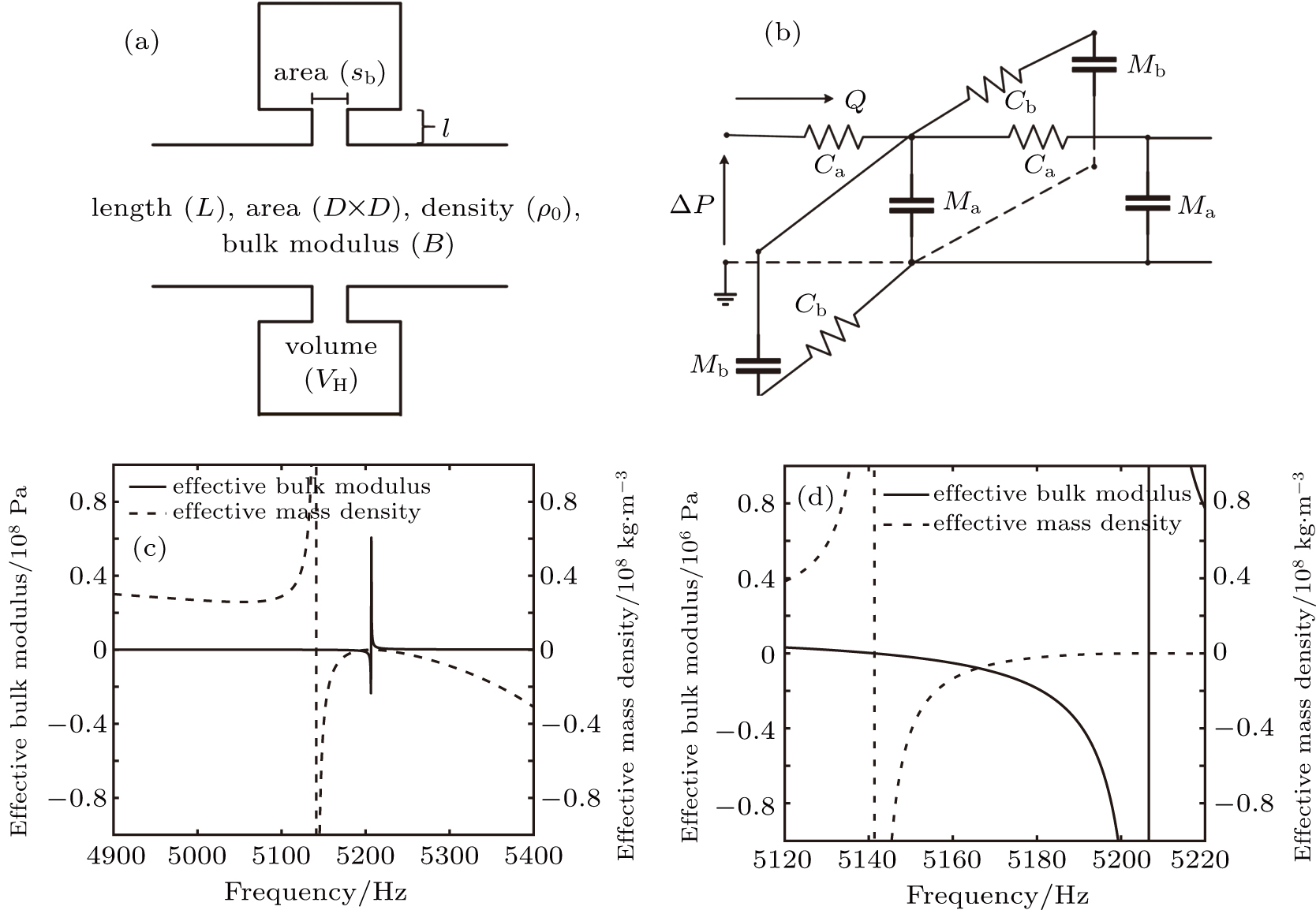
In order to explain the phenomenon, we use electro–acoustic analogy to analyze it. A unit cell is demonstrated in Fig. 2(a) with various parameters of the structure. The corresponding electric circuit analogy is presented in Fig. 2(b), in which the inductor and capacitor represent the equivalent acoustic mass and the stiffness of the half waveguide, respectively, where , c0, L, and D are the mass density of air, sound speed in air, length and width (the same with height) of the waveguide, respectively. Likewise, and donate the equivalent acoustic mass and the stiffness of the Helmholtz resonator, respectively, where l, r2, , and stand for the neck length, neck radius, neck area, and cavity volume of the Helmholtz resonator, respectively. It is important to note that the neck end correction of the HR is , which is composed of two parts, one side is when (r1 is the cavity radius of the HR) equals 0.25 and the other side is (to waveguide) according to the end correction theory.[25]

Fig. 2. (a) Unit cell of the waveguide with symmetric HRs. (b) Electric circuit analogy of the unit cell. (c) Effective bulk modulus and effective mass density for the unit cell. (d) Double-negative area of the unit cell.

From Fig. 2(b), the equivalent electrical impedance of the half waveguide can be given as where ZwL and ZwC are the equivalent electrical impedances of the inductance and capacitance with the following expressions: with c0 being the sound speed in the waveguide and .

Similarly, we can obtain the equivalent impedance of the Helmholtz resonator where ZHL and ZHC represent the equivalent electrical impedances of the inductance and capacitance of the Helmholtz resonator, respectively, with the following expressions: In accordance with Fig. 3(b), the total impedance of a unit cell can be given as With Eqs. (1)–(7), we can derive the total impedance as
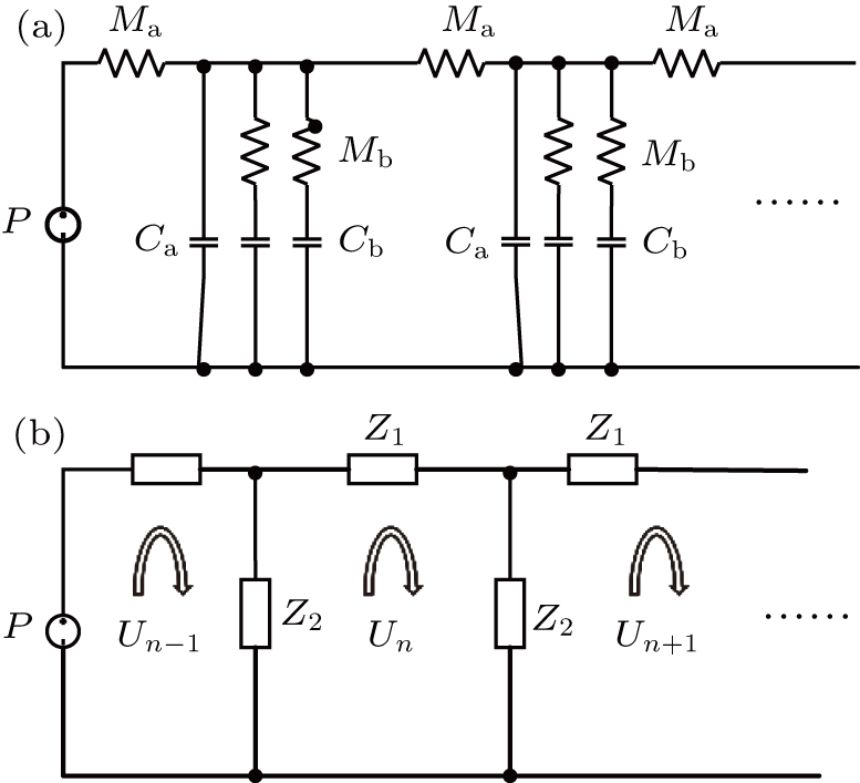
Fig. 3. (a) Electro–acoustic analogy of the waveguide with HRAs at the upper and lower surfaces of the waveguide and (b) the simplified electro–acoustic analogy.

In this case, the structure satisfies the situation , so we can do the following approximation: Combining the definition of the effective bulk modulus and the structure of the unit cell, we can easily obtain the effective bulk modulus where P is the acoustic pressure, Q and QH are the acoustic volume flow rates in the waveguide and Helmholtz resonators, respectively.

The acoustic volume flow rate in the waveguide can be given as The acoustic pressure and volume flow rate in the Helmholtz resonators are With Eqs. (11) and (12), equation (10) can be rewritten as Combining Eqs. (2), (4)–(6), (9), and (13), finally, we can obtain the parametric expression of , Meanwhile, the effective impedance of the unit open-circuit can be defined as The effective mass density is related to and by As a function of frequency, the effective bulk modulus and effective mass density are displayed in Fig. 2(c). We can see that there is a narrow frequency range of negative effective bulk modulus before the resonance frequency. The effective mass density turns negative above 5139 Hz and never goes back to positive. Obviously, there is some double-negative area around 5200 Hz. After zooming up, as Fig. 3(d) shows, a double-negative area from 5139 Hz to 5207 Hz is observed, which from the transmission line theory explains why this structure makes the radiation efficiency of an acoustic dipole enhance greatly.[26]

3.2. Acoustic filter

From another perspective, figure 3(a) presents the electro–acoustic analogy of the structure with HRAs as displayed in Fig. 1(b), which can also be regarded as an acoustic filter.[27] Ideally, the resistance of HR is quite small so that we can ignore it. The waveguide between two adjacent HRs is equivalently described by the acoustic mass Ma and stiffness Ca, likewise, Mb and Cb are the acoustic mass and stiffness of the HR, respectively, all the HRs are of the same size. The two HRs located in the corresponding positions of the upper and lower surfaces can be analogous to a pair of capacitor and inductor in parallel. To facilitate calculation, we simplify the acoustic impedance of the waveguide and parallel HRs with Ca as Z1 and Z2, respectively (Fig. 3(b)). We omit all the resistance of the same unit, where Un, and present the volume velocities in adjacent circuits, respectively. From the equivalent electric circuit, we have the following equations: that is Assume where θ is the phase difference between adjacent loops, α represents the transmission attenuation coefficient of the acoustic filter, and β is the phase coefficient. Then equation (18) can be written as In the pass band, the loss of the acoustic filter can be ignored, so . Therefore, we can obtain Apparently, that is here

Therefore the respective impedances must satisfy the following inequality: Solving the inequality, finally we can obtain the following solution:

That is to say, the waveguide with HRAs is equivalent to a bandpass filter at the resonance frequency of the HR. It explains why the two columns HRAs at the upper and lower surfaces of the waveguide can greatly increase the transmittance of the acoustic dipole at the frequency slightly below the resonance frequency of the Helmholtz resonator. Combined with the frequency band of double-negative area, the waveguide with HRAs can be seen as a narrow-band acoustic filter.

4. Results and discussion

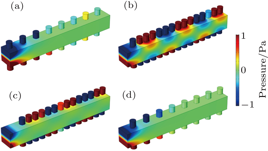
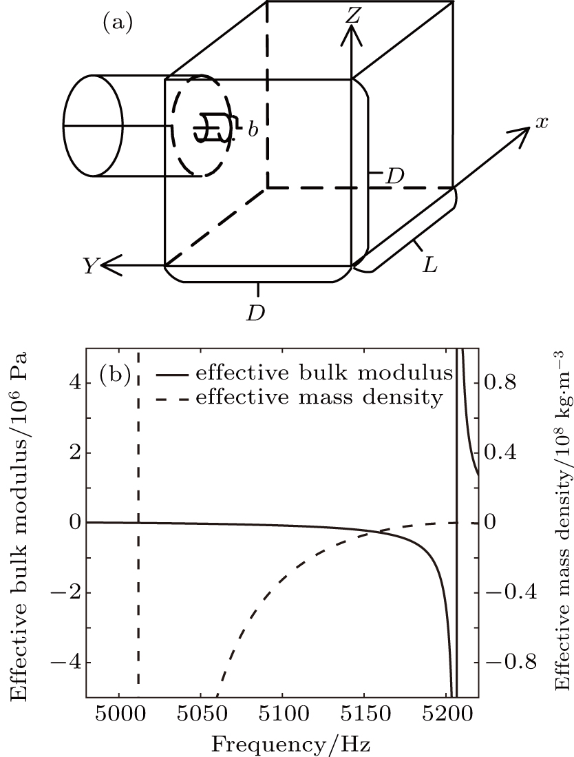
Next we will discuss how the arrangement of HRAs affects the transmission of the acoustic dipole. By changing the initial position and period of HRAs, we exam whether the dipole wave can still propagate in the waveguide. To explore this problem, we do the following simulation. By comparing with Fig. 1(b), the wave cannot propagate when we double the period of HRAs (Fig. 4(a)). In the situation shown in Fig. 4(b), alerting the first position of the HRAs and keeping the original period of the HRAs, the wave still propagates but there is a noticeable drop-off of the sound energy. When the initial position reaches far away to triple the distance, the HRAs lose their appeal to the sound source, causing the wave to lose propagation completely (Fig. 4(c)). Figure 4(d) shows the combination of the expansion of period and changing the first HR position of HRAs. Although the first HR position is not too far away from the dipole source and the sound energy can propagate to the position where the first two HRs exist, the period, i.e., the coupling strength is so weak, which determines that the wave cannot continue to propagate to the far field. Certainly, in extreme cases, that is, the first position of HRAs is relatively far, the period is also greater than the half-wavelength of the sound wave, then the HRAs have already lost their ability to attract and spread the sound, the sound wave induced by the dipole fails to propagate. Proper first HR position ensures that the dipole source can reach the HRAs and make HRAs function. As for the period of the HRAs, Ma and Ca change as periodic interval L varies. A unit cell of waveguide with the neck opening of HR is present in Fig. 5(a). After numerical calculation, when L = 5 mm and 10 mm, the double-negative areas are 5139–5207 Hz and 5010–5207 Hz, respectively. Combined with the filter theory, the actual transmissible frequency bands are 5139–5190 Hz and 5010–5152 Hz (Fig. 5(b)). Obviously, 5160 Hz is out of range of the transmissible frequency band, which leads to the failure in Fig. 4(d). In conclusion, the period of the HRAs determines the different transmissible frequency bands.

Fig. 4. Models of waveguides with different HRAs. (a) The first HR position of the HRAs is 2.5 mm, the period of the HRAs is 10 mm. (b) The first HR position of the HRAs is 7.5 mm, the period of the HRAs is 5 mm. (c) The first HR position of the HRAs is 12.5 mm, the period of the HRAs is 5 mm. (d) The first HR position of the HRAs is 7.5 mm, the period of the HRAs is 10 mm.
Fig. 5. (a) Unit cell of waveguide with Helmholtz resonator. (b) Double-negative area of the unit cell with L = 10 mm.
5. Conclusion

To enhance the transmittance of an acoustic dipole, a waveguide with two columns of HRAs at the upper and lower surfaces of the waveguide is proposed in this paper. By means of electro–acoustic analogy, a good explanation why the dipole wave can only be propagated to far field at the frequency below the resonance frequency of the HR is proposed. A double-negative area is present at the frequency slightly below the resonance frequency of the HR. It is found that the first position of the HRAs and the period of the HRAs have much to do with the transmittance. If the first position of the HRAs is too far away or the period of the HRAs is too large, it will cause the reduction of the attraction of the sound energy or the decline of the coupling intensity, which leads to the inability of the propagation of the wave. If the period is not matched with the half-wavelength of the sound wave, the wave shape distortion may occur although it can be transmitted. In conclusion, with proper first position and period of HRAs, HRAs at the surfaces of the waveguide can greatly improve the dipole transmission efficiency, which is fairly promising for the future application to acoustic superlenses.

Reference
[1] King W F 1977 Phys. Lett. A 62 282 https://doi.org/10.1016/0375-9601(77)90798-8
[2] Li Y L Ma Q Y Zhang D 2011 Chin. Phys. B 20 084302 https://doi.org/10.1088/1674-1056/20/8/084302
[3] Guan C M Ping S 2016 Sci. Adv. 2 e1501595 https://doi.org/10.1126/sciadv.1501595
[4] Feng Q Li Q Li W W Xiao Z L Xiu F G 2016 Chin. Phys. B 25 24301 https://doi.org/10.1088/1674-1056/25/2/024301
[5] Groby J P Lagarrigue C Brouard B Dazel O Tournat V Nennig B 2015 J. Acoust. Soc. Am. 137 273 https://doi.org/10.1121/1.4904534
[6] Li Q Feng Q Liu X Gong X 2016 J. Acoust. Soc. Am. 139 3373 https://doi.org/10.1121/1.4949542
[7] Yan F L Hui J Lin K Z Yong S S Dian L Y 2016 Phys. Lett. A 380 2322 https://doi.org/10.1016/j.physleta.2016.05.017
[8] Quan L Zhong X Liu X Gong X Johnson P A 2014 Nat. Commun. 5 3188 https://doi.org/10.1038/ncomms4188
[9] Quan L Qian F Liu X Gong X 2015 J. Acoust. Soc. Am. 138 782 https://doi.org/10.1121/1.4926898
[10] Quan L Qian F Liu X Gong X Johnson P A 2015 Phys. Rev. B 92 104105 https://doi.org/10.1103/PhysRevB.92.104105
[11] Ying C Jun Y X Xiao J L J 2008 Phys. Rev. B 77 045134 https://doi.org/10.1103/PhysRevB.77.045134
[12] Ning L Wang Y Z Wang Y S 2019 Int. J. Mech. Sci. 153–154 287 https://doi.org/10.1016/j.ijmecsci.2019.02.007
[13] Baz A M 2010 ASME J. Vib. Acoust. 132 041011 https://doi.org/10.1115/1.4000983
[14] Shen H J Paidoussis M P Wen J H Yu D L Cai L Wen X S 2012 J. Phys. D: Appl. Phys. 45 285401 https://doi.org/10.1088/0022-3727/45/28/285401
[15] Akl W Baz A 2011 Smart Mater Struct. 20 125010 https://doi.org/10.1088/0964-1726/20/12/125010
[16] Zhu J Christensen J Jung J Martin-Moreno L Yin X Fok L Zhang X Garcia-Vidal F J 2011 Nat. Phys. 7 52 https://doi.org/10.1038/nphys1804
[17] Kaina N Lemoult F Fink M Lerosey G 2015 Nature 525 77 https://doi.org/10.1038/nature14678
[18] Hou Y L Ying C Xiao J L 2017 Appl. Phys. Lett. 111 143502 https://doi.org/10.1063/1.4998516
[19] Dylan L Zhao W L 2012 Nat. Commun. 3 1205 https://doi.org/10.1038/ncomms2176
[20] Park J J Park C M Lee K J B Lee S H 2015 Appl. Phys. Lett. 106 051901 https://doi.org/10.1063/1.4907634
[21] ohn B P 2000 Phys. Rev. Lett. 85 3966 https://doi.org/10.1103/PhysRevLett.85.3966
[22] Viktor A P Evgenii E N 2005 Opt. Lett. 30 75 https://doi.org/10.1364/OL.30.000075
[23] Chen S Yun J 2014 Appl. Phys. A 117 1885 https://doi.org/10.1007/s00339-014-8603-0
[24] Xi S Y Jing Y Gao K Y Lin H P Ning W 2015 Appl. Phys. Lett. 107 193505 https://doi.org/10.1063/1.4935589
[25] Ingard U 1953 J. Acoust. Soc. Am. 25 1037 https://doi.org/10.1121/1.1907235
[26] Nicholas F Dong J X Jiang Y X Muralidhar A Werayut S Cheng S Xiang Z 2006 Nat. Mater. 5 452 https://doi.org/10.1038/nmat1644
[27] Morse P M Ingard U K 1968 Theoretical Acoustics New York McGraw-Hill 467 https://doi.org/10.1119/1.1976432