Comparison of three kinds of polarized Bessel vortex beams propagating through uniaxial anisotropic media
Liu Jia-Wei, Li Hai-Ying, Ding Wei, Bai Lu, Wu Zhen-Sen, Li Zheng-Jun
School of Physics and Optoelectronic Engineering, Xidian University, Xi’an 710126, China


† Corresponding author. E-mail: lihy@xidian.edu.cn

Abstract

A comparison of differently polarized Bessel vortex beams propagating through a uniaxial anisotropic slab is discussed in terms of the vector wave function expansions. The magnitude profiles of electric field components, the transformation of polarization modes, and the distributions of orbital angular momentum (OAM) states of the reflected and transmitted beams for different incident angles are numerically simulated. The results indicate that the magnitude profiles of electric field components for different polarization modes are distinct from each other and have a great dependence on the incident angle, thus the transformation of polarization modes which reflects the change of energy can be affected largely. As compared to the x and circular polarization incidences, the reflected and transmitted beams for the radial polarization incidence suffer the fewest transformation of polarization modes, showing a better energy invariance. The distributions of OAM states of the reflected and transmitted beams for different polarization modes are diverse as well, and the derived OAM states of the transmitted beam for radial polarization present a focusing effect, concentrating on the state between two predominant OAM states.

1. Introduction

The vortex beams carrying orbital angular momentum (OAM)[1] have been widely studied over a few past decades, including generation,[2,3] characteristics,[46] and applications in optical communication,[7] imaging,[8] micro-particle manipulation,[9] etc. In particular, the different OAM states are mutually orthogonal while propagating coaxially and thus promote potential applications in improving the capacity of communication systems. Gibson et al. implemented the initial demonstration of using OAM for free-space communication, experimentally proving the possibility of transmitting information by vortex beams.[10] The team led by Wang has been working on the multiplex/demultiplex of OAM in the optical band and has obtained several valuable research results.[11,12] Appreciable literatures on the transmission efficiency,[1315] the security performance,[16] and the mitigation of crosstalk[17] of vortex beams have been reported. Some other researches which are worth mentioning also boost the development of vortex beams in quantum communication,[18] RF communication,[19] and material processing.[20] Whereas, the propagation of vortex beams in media inevitably results in the distortion of electric field amplitude and further causes the crosstalk of OAM states.[21] Such distortion is even serious in anisotropic media because of the double refraction behavior. Yu[22] and Wang[23] studied the propagation of Airy Gaussian vortex beams and chirped Airy vortex beams in uniaxial crystals, respectively. The results prove that the ratio of extraordinary and ordinary refractive indices affects the asymmetry of the intensity a lot. As a kind of typical anisotropic media, uniaxial anisotropic media are widely applied in optical signal processing,[24] optical element design,[25] and manufacturing of microwave devices.[26] Exploring the variations of field profile, polarization mode, and OAM state of the reflected and transmitted beams during the propagation of vortex beams in uniaxial media can potentially improve the quality and efficiency of practical applications.[27]

Compared to other vortex beams, Bessel vortex beams[28] whose electric field intensity is independent of propagation distance are treated to be more advantageous for long-distance communication,[29] optical imaging,[30] and other applications[31,32] since its field profile can self-reconstruct after passing through obstacles. Besides, such diffraction-free beams suffer less power loss than Gaussian beams,[33] which means a higher signal-noise ratio in practical optical communication. With the need of large data transmission for optical communication, according to the Fresnel–Arago interference law,[34] the general way is to use the same information-carrying beams with two orthogonal linear polarization modes at the input of an optical communication system to provide twofold data channels.[35] However, it will lower the transmission efficiency of communication systems because there must be corresponding polarizers at the receiving end to decode the information carried by beams with different linear polarization modes. A high extinction ratio polarization beam splitter skillfully utilizing the displacements of TE- and TM-polarized beams in a low-symmetric photonic crystal was designed to simplify the optical communication system in the precondition of high transmission efficiency.[36] Furthermore, Quabis et al. found that the radially polarized beams have the favorable focusing characteristic which could be used to build improved near field sensors.[37] Generally speaking, the polarized Bessel vortex beams (PBVBs) which simultaneously possess the polarization characteristics and OAM properties are potential to increase information capacity and transmission efficiency by combining with the polarization–division multiplexing (PDM) and mode–division multiplexing (MDM) systems. However, in this case, the distortion of electric fields and the crosstalk of OAM states stemming from the transformation of polarization modes need to be taken into account. As far back as 2001, Nesterov and Niziev had investigated the propagation characteristics of beams with axially symmetric polarization, finding that such polarized beams are free from polarization aberrations.[38] King also found the derivation of topological charge of a circularly polarized Bessel vortex beam in biaxial crystals and demonstrated the transformation of a Bessel beam from zeroth to first order and then from first to second order.[39] Furthermore, the oscillating polarization along the optical axis of Bessel beams in free space was discussed by Fu and his co-worker.[40] It seems that the influence of polarization mode on the propagation of a Bessel vortex beam is still worth considering for further understanding, especially in the communication systems involving both polarization–division multiplexing and OAM–division multiplexing.

In this paper, the comparison of three kinds of polarized Bessel vortex beams incident on a uniaxial anisotropic slab is investigated by use of the cylindrical vector wave function expansions and the eigen plane wave spectrum representation. The paper is arranged as follows: section 2 gives the expressions of the incident, reflected, and transmitted fields, as well as the field in the internal slab in terms of the cylindrical vector wave functions (CVWFs). On this basis, the reflected and transmitted field components are simulated numerically and discussed in section 3, including the transformation of polarization modes and the OAM state distribution of the reflected and transmitted beams for different incident angles and for different polarization modes. Section 4 presents the conclusions.

2. Theoretical background

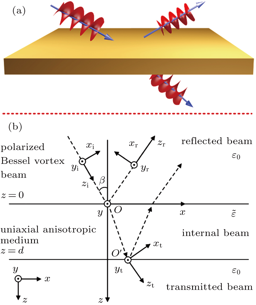
The sketch of an arbitrary polarized Bessel vortex beam which is obliquely incident on a uniaxial anisotropic slab is shown in Fig. 1. Figure 1(a) is the graphic model and describes the geometrical relationship between the global system and the local coordinate systems. The origins of the incident and reflected coordinate systems ( and ) coincide with those of the global coordinate system. The outgoing point of ordinary wave in slab is chosen as the origin of the transmitted coordinate system for the convenience of estimating the displacement by Snellʼs law. The incident angle and the thickness of slab are β and d, respectively. In this paper, the time-harmonic factor is .

Fig. 1. Oblique incidence of an arbitrarily polarized Bessel vortex beam on a uniaxial anisotropic slab.

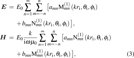
According to the angular spectrum decomposition (ASD) method, the electric and magnetic field vectors of a polarized Bessel vortex beam under the incident coordinate system are expressed as[41]

where corresponds to the position of beam center in the global coordinate system, which is set to . is the wave vector. The notations l and are the topological charge and the half cone angle of the incident beam, respectively. is the amplitude of the electric field of the plane waves propagating over a cone. and denote, respectively, the polar and azimuthal angles of the wave vector under the incident coordinate system. ω is the circular frequency. The complex polarization function for arbitrary polarization is written as[42]
with being the complex polarization parameters. are unit vectors of the Cartesian incident system. Specifically, stands for the x polarization, the circular polarization (left-hand in this paper), and the radial polarization, respectively.

By expanding the factor in terms of the spherical vector wave functions (SVWFs), the electric and magnetic field vectors of a PBVB can be expressed as[43]

where and are the SVWFs belonging to the incident coordinate system, and the superscript (1) represents the spherical Bessel function of the first kind. The expansion coefficients amn and bmn are as follows:
where and are the coefficients shown in Ref. [43], . and are the angle functions.

Considering the incident angle β, by utilizing the addition theorem of the SVWFs, the electric field vector of the incident beam can be expressed under the global coordinate system Oxyz as[44]

where and are the SVWFs belonging to Oxyz. Here, the superscript i refers to the incident beam. The expansion coefficients and are
and the specific expression of can be found in Ref. [45].

According to the transformation relationship between the SVWFs and the CVWFs,[44] equation (5) can be rewritten by means of the CVWFs as

where and are the CVWFs belonging to the global coordinate system. , , . ζ is the angle between the wave vector and the z axis. The corresponding expansion coefficients and are as follows:
where

The corresponding expansion for the magnetic field vector can be obtained by Maxwell equations.

Let us consider the actual incidence of a PBVB which can be interpreted as the superposition of plane wavelets. Under this proposition, only the plane wavelets which illuminate on the upper surface of the slab are considerable, which means that the integration interval of ζ in Eq. (7) is from 0 to π/2.

Similarly, the electric field vectors of the reflected and transmitted beams are as follows:

where the superscripts r and t are the symbols of the reflected and transmitted beams, respectively. and are the corresponding expansion coefficients.

The electric field of the internal beam in a uniaxial anisotropic slab whose optic axis is perpendicular to the upper surface ( is the permittivity) is given by the Fourier transform and the eigen plane wave spectrum representation[46]

where the coefficients , , and can be found in Ref. [46]. The superscript w denotes the internal beam, and the subscripts 1 and 2 refer to the down- and up-going waves, respectively. The integer indices q = 1,2 give the explanation to the double refraction behavior of a uniaxial anisotropic slab. Emq and Fmq are the expansion coefficients.

Through the electromagnetic fields boundary conditions that the tangential components of the electromagnetic fields are continuous, a set of simultaneous equations can be obtained, from which the expansion coefficients and then the corresponding field components can be solved numerically.

To analyze the effects of such media on the transformation of polarization modes during the propagation of a PBVB, the following expression[47] which is similar to the definition of the polarization extinction ratio (PER) is used to investigate the polarization characteristics of the reflected and transmitted beams:

where stand for the reflected and transmitted beams, respectively. denotes the longitudinal component of the time-average Poynting vector power density resulted from the electric field component , with corresponding the electric field component .

Similar to the angular spectrum decomposition, vortex beams can be interpreted as the superposition of infinite spiral harmonics according to the expansion of spiral spectrum.[48] n is the integer index and ϕ stands for the phase factor. In this way, the field components of the reflected and the transmitted beams can be expressed as follows:

where U refers to the electric field components or the magnetic field components , and the coefficient means the amplitude of the corresponding spiral harmonic component and can be expressed as

As we all know that the time-averaged energy density of a beam is , where and are the permittivity and the permeability of vacuum, respectively. Substituting Eq. (16) into the time-averaged energy density expression, we finally arrive at the weight function of OAM states

3. Numerical simulations and discussion

To intuitively analyze the influence of the incident angle and polarization on the deformations of the electric field amplitude and OAM state, as well as the transformation of polarization mode, numerical simulations are given below by using the theoretical formulae derived in section 2. The wavelength is . The half-cone angle and the topological charge of the incident PBVB are set as and l = 2, respectively. The parameters of the uniaxial anisotropic slab are as follows: , , and (Calcite).

3.1. Comparison of magnitude profiles of electric field components of the incident, reflected, and transmitted beams

Figure 2 shows the magnitude profiles of the incident electric field components. The row-panels represent the polarization modes, i.e., x polarization (x polar.), circular polarization (circ polar.), and radial polarization (rad. polar.), from up to down, respectively) of the incident beam, and the column-panels stand for the electric field components ( , and from left to right, respectively). Such results bring into correspondence with the numerical simulations in Ref. [49], proving the reasonability of the method used in this paper.

Fig. 2. Magnitude profiles of the electric field components of incident beam for different polarization modes.

As we can see from Fig. 2 that the electric field component is prominent in the case of x polarization with a circular symmetric structure. For circular polarization incidence, all of the electric field components keep circular symmetry and the transverse electric field components and have the same magnitude profiles. Although the longitudinal electric component maintaining circular symmetry for radial polarization incidence, the transverse electric field components both have an axial symmetric crescent contour.

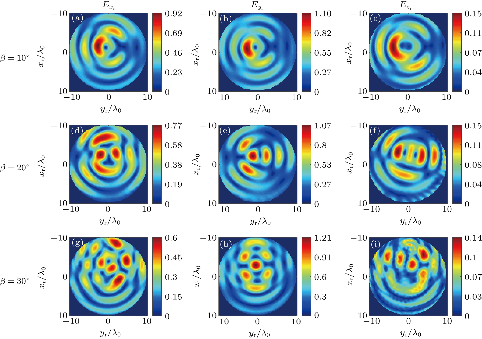
The magnitude profiles of electric field components of the reflected beam for different polarization modes are displayed in Figs. 35. Each figure includes 9 panels, where the row-panels represent the cases of different incident angles (10°, 20°, and 30° from up to down, respectively) and the column-panels represent the electric field components ( , and from left to right, respectively).

Fig. 3. Magnitude profiles of the reflected electric field components for the x polarized incidences.
Fig. 4. Magnitude profiles of the reflected electric field components for the circularly polarized incidence.
Fig. 5. Magnitude profiles of the reflected electric field components for the radially polarized incidence.

It can be seen from Figs. 35 that as the incident angle increases, the contours of the reflected field components for all three kinds of polarization modes are seriously distorted, associating with a gradually increasing displacement along the negative xr axis. It is because that the reflected beam contains the beams reflected by both upper and lower surfaces of the slab, these beams superimpose together resulting in the more deformed contours. Such a process occurs in the transmitted beams too, but the low reflectance mitigates the distortion caused by the superimposition. In addition, the magnitudes of electric field components decrease, which are just opposite to the electric field component . The magnitude profile of the electric field component for the x polarization incidence is similar to the components and for the circular polarization incidence, as well as the changing trend with the increasing incident angle just as figure 3 and 4 show.

Compared to the circular polarization incidence, the difference between the maximum values of the transverse electric field components and for the radial polarization incidence is smaller, which means that there are fewer changes for the polarization mode. Furthermore, the reflected beam for such polarization incidence has the biggest longitudinal electric field component as shown in Fig. 5.

Similarly, the magnitude profiles of electric field components of the transmitted beam are presented in Figs. 68, where the row-panels also represent the cases of different incident angles and the column-panels represent the transmitted electric field components ( , , and from left to right, respectively).

Fig. 6. Magnitude profiles of the transmitted electric field components for the x polarized incidence.
Fig. 7. Magnitude profiles of the transmitted electric field components for the circularly polarized incidence.
Fig. 8. Magnitude profiles of the transmitted electric field components for the radially polarized incidence.

Just as the behaviors of reflected field components, the magnitude profiles of the transmitted field components also have distortions. Comparing with the incident beams, the central circular rings in the contours shown in Figs. 68 have changed significantly, especially for the circular polarization incidence. Meanwhile, as the incident angle increases, the distortion of the central ring is more remarkable. Figure 7 shows the appearance of a rotation in 180° in the contour variations of the central circular rings in both and .

To have a clear understanding about the variations of the polarization of the reflected and transmitted beams, the value of Pol by Eq. (14) is used to analyze the transformation of polarization modes.

3.2. Transformation of polarization modes of the reflected and transmitted beams

In order to provide a reference for comparison, the polarization patterns of the incident beams are presented in Fig. 9.

Fig. 9. Polarization patterns of the incident beam: (a) x polarization; (b) circular polarization; (c) radial polarization.

Figure 9 indicates that the electric field vectors of the incident beam with the x polarization are along the xi axis, and for the circular polarization, the electric field vectors form the shape of a hexagonal star whose points are located at infinity. The polarization pattern of the radially polarized incident beam is more intricate. The electric field vectors outside the second bright ring are along the radial direction. Inside the second bright ring, the electric field vectors start from two source points and disappear in the other two end points as figure 9(c) shows.

Figure 10 and 11 show the polarization patterns of the reflected and transmitted beams for different incident angles. The row-panels represent the cases of polarization modes (x, circular, and radial polarizations from up to down, respectively), and the column-panels stand for the cases of different incident angles (10°, 20°, and 30° from left to right, respectively).

Fig. 10. Polarization patterns of the reflected beam with different incident angles.
Fig. 11. Polarization patterns of the transmitted beam with different incident angles.

It can be seen from Figs. 10 and 11 that the original polarization modes are largely destroyed after reflection. However, the electric field vectors inside the yellow rectangle are similar to the polarization pattern of the incident beam when the incident angle is 30°, showing better resilience as the incident angle increases. It reveals that the direction of electric field vectors inside the blue circle is comparable to that of the incident beam in Fig. 9(c) when the incident angle equals 30° as shown in Fig. 10(i). At the same incident angle, the electric field vectors of the reflected beam are more rambling compared with those of the transmitted beam, and the polarization patterns of the transmitted beam hold similar contours to the incident beam when the incident angle is small. Such contours would be ruined gradually with the increase of the incident angle.

Tables 1 and 2 show the values of Pol of the reflected and transmitted beams with different incident angles for three kinds of polarization modes. Cases 1, 2, and 3 stand for the x, circular, and radial polarizations, respectively.

Table 1.

Pol of the reflected beam with different incident angles.

.
Table 2.

Pol of the transmitted beam with different incident angles.

.

It reveals in Tables 1 and 2 that the values of Pol for the x polarization incidence decrease as the incident angle increases, which means that there is more energy transmitting into the electric field component from , reaching an agreement with the change trend as shown in Figs. 3 and 6. As for the circular polarization incidence, the polarization mode of the transmitted beam has a similar behavior to that of x polarization incidence, but the negative value of Pol indicates that the energy of electric field component is always higher than . In addition, the reflected beam whose value of Pol first rises to −0.83 from −0.87 and then drops to −5.24, goes through a non-monotonic transformation of polarization modes. Compared to the circular polarization incidence, the transformation trend of polarization modes of the reflected beam for the radial polarization incidence is similar, but the variation of the transmitted beam is just opposite.

3.3. Comparison of OAM states of the reflected and transmitted beams

The transformation of polarization modes finely reflects the energy transfer along the polarization directions. However, for practical applications of vortex beams, the investigation into the energy of each helical harmonic is important as well, especially in an OAM multiplexing system. To analyze the effects of polarization modes and incident angles on the deformation of OAM states, figures 12 and 13 plot the distributions of OAM states of the reflected and transmitted beams, respectively.

Fig. 12. OAM states of the reflected beam with different incident angles and polarization modes.
Fig. 13. OAM states of the transmitted beam with different incident angles and polarization modes.

Figures 12 and 13 illustrate that as the incident angle increases, there are more adjacent OAM states derived in the reflected and transmitted beams, and the distributions of OAM states of the reflected beam are more complicated than those of the transmitted beam. The reflected beams for the x and circular polarization incidences have only single predominant OAM state −l whose value is opposite to that of the transmitted beams l. However, the reflected beam for the radial polarization incidence has double predominant OAM states and , and the corresponding predominant OAM states of the transmitted beam are and , which brings into the correspondence with the analytic expression of the radially polarized Bessel vortex beam.[50] The negative predominant OAM states of the reflected beam can be interpreted by the reflection effect of vortex beams, which can be applied to the data swapping.[51] For the reflected beam, the energy of predominant OAM states firstly decreases and then increases as the incident angle gets bigger, and the energy of derived OAM states is gradually away from the predominant OAM state, which will cause fewer crosstalk problems. Instead, in the transmitted beam, the energy of predominant OAM states keeps a continuous consumption as the incident angle increases. Furthermore, the polarization modes of the incident beam have significant influences on the distributions of OAM states of the reflected and transmitted beams. The most obvious difference is the number of the predominant OAM state. At the same incident angle, the OAM state distribution of the reflected beam presents symmetric bar graphs centered on the OAM state −l, with two predominant states for radial polarization incidence and similar structures between x and circular polarization incidences. However, such symmetric structures are ruined in the transmitted beam for the case of circular polarization incidence. The most mentionable point is that the energy of the derived OAM states in transmitted beam for the radial polarization incidence focuses on the OAM state l, which is beyond our expectation.

4. Conclusions

The reflection and transmission of a PBVB by a uniaxial anisotropic slab had been investigated by use of the cylindrical vector wave function expansions. The electromagnetic fields of the incident, reflected, and transmitted beams, as well as their corresponding expansion coefficients, were obtained utilizing the CVWFs. The magnitude profiles of the field components, the transformation of polarization modes, and the distributions of OAM states of the reflected and transmitted beams were analyzed in detail. The results indicated that the magnitude profiles of the reflected field components were more obviously complicated than those of the transmitted field components, and their contours are seriously distorted as the incident angle increases. Compared to x and radial polarization incidences, the reflected beam for the circular polarization incidence had the minimum transformation of polarization modes between the transverse electric field components. Although the magnitude profiles of the reflected field components for three kinds of polarization modes were in wild disorder with a bigger incident angle, the energy of the reflected beam seemed to go back to the predominant OAM states. Different from the cases of x and circular polarization incidences, the derived OAM states in the transmitted beam for the radial polarization incidence located at the OAM state between its two predominant OAM states, leading to the focused effect of OAM state. The results in this paper may provide some supports in the design of optical devices and the OAM multiplexing communication combining with a polarization–division multiplexing segment.

Reference
[1] Allen L Beijersbergen M W Spreeuw R J Woerdman J P 1992 Phys. Rev. A 45 8185 https://doi.org/10.1103/PhysRevA.45.8185
[2] Wang C Shao Q Liu T Ren Y 2018 Optical Precision Manufacturing, Testing and Applications 10847 1084703 https://doi.org/10.1117/12.2502766
[3] Ruffato G Massari M Romanato F 2014 Opt. Lett. 39 5094 https://doi.org/10.1364/OL.39.005094
[4] Novitsky A V Barkovsky L M 2008 J. Opt. A-Pure. Appl. Opt. 10 075006 https://doi.org/10.1088/1464-4258/10/7/075006
[5] Zhou Z Guo Y Zhu L 2014 Chin. Phys. B 23 044201 https://doi.org/10.1088/1674-1056/23/4/044201
[6] Belyi V N Khilo N A Kazak N S Ryzhevich A A Forbes A 2011 Opt. Eng. 50 059001 https://doi.org/10.1117/1.3572109
[7] Bozinovic N Yue Y Ren Y Tur M Kristensen P Huang H Willner A E Ramachandran S 2013 Science 340 1545 https://doi.org/10.1126/science.1237861
[8] Yan L Gregg P Karimi E Rubano A Marrucci L Boyd R Ramachandran S 2015 Optica 2 900 https://doi.org/10.1364/OPTICA.2.000900
[9] Rui G Gu B Zhan Q Cui Y 2016 Prog. Electromagn. Res. Symp. (PIERS) 738 739 https://doi.org/10.1109/PIERS.2016.7734441
[10] Gibson G Courtial J Padgett M J Vasnetsov M Pas’ko V Barnett S M Franke-Arnold S 2004 Opt. Express 12 5448 https://doi.org/10.1364/OPEX.12.005448
[11] Wang J Li S Luo M Liu J Zhu L Li C Xie D Yang Q Yu S Sun J 2014 Eur. Conf. Opt. Commun. (ECOC) 1 3 https://ieeexplore.ieee.org/document/6963934
[12] Wang J Liu J Lv X Zhu L Wang D Li S Wang A Zhao Y Long Y Du J 2015 Eur. Conf. Opt. Commun. (ECOC) 1 https://doi.org/10.1109/ECOC.2015.7341894
[13] Chaudhary S Amphawan A 2018 Photon. Netw. Commun. 35 374 https://doi.org/10.1007/s11107-017-0752-6
[14] Huang H Xie G Yan Y Ahmed N Ren Y Yue Y Rogawski D Willner M J Erkmen B I Birnbaum K M Dolinar S J Lavery M P Padgett M J Tur M Willner A E 2014 Opt. Lett. 39 197 https://doi.org/10.1364/OL.39.000197
[15] Zhu L Zhu G Wang A Wang L Ai J Chen S Du C Liu J Yu S Wang J 2018 Opt. Lett. 43 1890 https://doi.org/10.1364/OL.43.001890
[16] Djordjevic I B Zhang S L Wang T 2017 13th International Conference on Advanced Technologies, Systems and Services in Telecommunications (Telsiks) 317
[17] Sun T F Liu M W Li Z X Li Y C Zhang Q W Wang M 2017 Opto-Electron. Commun. Conf. (Oecc) Photon. Global Conf. (Pgc) 1 10.1109/OECC.2017.8114783
[18] Ndagano B Nape I Cox M A Rosales-Guzman C Forbes A 2018 J. Lightwave Technol. 36 292 https://doi.org/10.1109/JLT.2017.2766760
[19] Zhao M Gao X Xie M Qian J Song C Huang S 2018 Opt. Commun. 426 126 https://doi.org/10.1016/j.optcom.2018.05.028
[20] Stoian R Bhuyan M K Zhang G Cheng G Meyer R Courvoisier F 2018 Adv. Opt. Technol. 7 165 https://doi.org/10.1515/aot-2018-0009
[21] Djordjevic I B 2011 Opt. Express 19 14277 https://doi.org/10.1364/OE.19.014277
[22] Yu W H Zhao R H Deng F Huang J Y Chen C D Yang X B Zhao Y P Deng D M 2016 Chin. Phys. B 25 044201 https://doi.org/10.1088/1674-1056/25/4/044201
[23] Wang L Y Zhang J B Feng L Y Pang Z H Zhong T F Deng D M 2018 Chin. Phys. B 27 054103 https://doi.org/10.1088/1674-1056/27/5/054103
[24] Lo Y L Yu T C 2006 Opt. Commun. 259 40 https://doi.org/10.1016/j.optcom.2005.08.061
[25] Lu K Saleh B E 1990 Opt. Eng. 29 240 https://doi.org/10.1117/12.55584
[26] Chugunov Y V Shirokov E A Fomina I A 2015 Radiophys. Quant. EL + 58 318 https://doi.org/10.1007/s11141-015-9606-1
[27] Li H Y Liu J W Bai L Wu Z S 2018 Appl. Opt. 57 7353 https://doi.org/10.1364/AO.57.007353
[28] Durnin J Miceli J Jr. Eberly J H 1987 Phys. Rev. Lett. 58 1499 https://doi.org/10.1103/PhysRevLett.58.1499
[29] Zhang Y L Ma D L Yuan X H Zhou Z Y 2016 Appl. Opt. 55 9211 https://doi.org/10.1364/AO.55.009211
[30] Chen B Y Huang X S Gou D Z Zeng J Z Chen G Q Pang M J Hu Y H Zhao Z Zhang Y F Zhou Z Wu H T Cheng H P Zhang Z G Xu C Li Y L Chen L Y Wang A M 2018 Biomed. Opt. Express 9 1992 https://doi.org/10.1364/BOE.9.001992
[31] McGloin D Garces-Chavez V Dholakia K 2003 Opt. Lett. 28 657 https://doi.org/10.1364/OL.28.000657
[32] Volke-Sepulveda K Garces-Chavez V Chavez-Cerda S Arlt J Dholakia K 2002 J. Opt. B-Quantum S. O 4 S82 https://doi.org/10.1088/1464-4266/4/2/373
[33] Birch P Ituen I Young R Chatwin C 2015 J. Opt. Soc. Am. A 32 2066 https://doi.org/10.1364/JOSAA.32.002066
[34] Collett E 1971 Am. J. Phys. 39 1483 https://doi.org/10.1119/1.1976702
[35] Wang J Yang J Y Fazal I M Ahmed N Yan Y Huang H Ren Y X Yue Y Dolinar S Tur M Willner A E 2012 Nat. Photon. 6 488 https://doi.org/10.1038/nphoton.2012.138
[36] Yasa U G Turduev M Giden I H Kurt H 2017 J. Lightwave Technol. 35 1677 https://doi.org/10.1109/JLT.2017.2657697
[37] Quabis S Dorn R Eberler M Glockl O Leuchs G 2000 Opt. Commun. 179 1 https://doi.org/10.1016/S0030-4018(99)00729-4
[38] Nesterov A V Niziev V G 2001 J. Opt. B-Quantum. S O 3 S215 https://doi.org/10.1088/1464-4266/3/2/372
[39] King T A Hogervorst W Kazak N S Khilo N A Ryzhevich A A 2001 Opt. Commun. 187 407 https://doi.org/10.1016/S0030-4018(00)01124-X
[40] Fu S Zhang S Gao C 2016 Sci. Rep-Uk 6 30765 https://doi.org/10.1038/srep30765
[41] Mitri F G Li R X Guo L X Ding C Y 2017 J. Quantum Spectrosc. Radiat. Transfer 187 97 https://doi.org/10.1016/j.jqsrt.2016.09.023
[42] Chen J Ng J Wang P Lin Z F 2010 Opt. Lett. 35 1674 https://doi.org/10.1364/OL.35.001674
[43] Ma X B Li E B 2010 Chin. Opt. Lett. 8 1195 https://doi.org/10.3788/COL20100812.1195
[44] Gouesbet G Wang J J Han Y P 2010 Opt. Commun. 283 3235 https://doi.org/10.1016/j.optcom.2010.04.051
[45] Zhang H Y Han Y P 2008 J. Opt. Soc. Am. B 25 255 https://doi.org/10.1364/JOSAB.25.000255
[46] Wang M J Zhang H Y Liu G S Li Y L Dong Q F 2014 Opt. Express 22 3705 https://doi.org/10.1364/OE.22.003705
[47] Li H Y Honary F Wang J J Liu J W Wu Z S Bai L 2018 Appl. Opt. 57 1967 https://doi.org/10.1364/AO.57.001967
[48] Jiang Y S Wang S H Zhang J H Ou J Tang H 2013 Opt. Commun. 303 38 https://doi.org/10.1016/j.optcom.2013.04.013
[49] Wang J J Wriedt T Lock J A Madler L 2016 J. Quantum. Spectrosc Radiat. Transfer 184 218 https://doi.org/10.1016/j.jqsrt.2016.07.011
[50] Wang J J Wriedt T Lock J A Jiao Y C 2017 J. Quantum Spectrosc. Radiat. Transfer 195 8 https://doi.org/10.1016/j.jqsrt.2016.10.010
[51] Yue Y Huang H Ahmed N Yan Y Ren Y X Xie G D Rogawski D Tur M Willner A E 2013 Opt. Lett. 38 5118 https://doi.org/10.1364/OL.38.005118