School of Physics and Optoelectronic Engineering, Foshan University, Foshan 528000, China
Department of Physics, Collaborative Innovation Center for Optoelectronic Semiconductors and Efficient Devices, and Jiujiang Research Institute, Xiamen University, Xiamen 361005, China
Project supported by the National Natural Science Foundation of China (Grant Nos. 11604050, 91636109, 61575041, and 61875242), the Fundamental Research Funds for the Central Universities at Xiamen University, China (Grant No. 20720190057), the Natural Science Foundation of Fujian Province of China for Distinguished Young Scientists (Grant No. 2015J06002), the Program for New Century Excellent Talents in University of China (Grant No. NCET-13-0495), the Science and Technology Planning Project of Guangdong Province, China (Grant No. 2016B010113004), and the Natural Science Foundation of Guangdong Province, China (Grant Nos. 2015A030310296 and 2018A030313347).
Abstract
Abstract
We propose a simple and efficient method that uses a single focused hybrid vector beam to confine metallic Rayleigh particles at multiple positions. We study the force mechanisms of multiple trapping by analyzing the gradient and scattering forces. It is observed that the wavelength and topological charges of the hybrid vector beam regulate the trapping positions and number of optical trap sites. The proposed method can be implemented easily in three-dimensional space, and it facilitates both trapping and organization of particles. Thus, it can provide an effective and controllable means for nanoparticle manipulation.
Ever since Ashkin first demonstrated the use of laser beams to accelerate and trap micrometer-sized particles,[1] this noncontact and noninvasive technology, called optical tweezers, has become a powerful tool for several fields such as biology, physical chemistry, and medicine.[2–4] Nowadays, optical manipulation is being widely used in several tasks such as moving biological objects, trapping and cooling of atoms, and separating dielectric particles.[5–7] Initially, optical tweezers used a microscope objective lens to focus a linearly polarized Gaussian beam for a single optical trapping. These conventional linearly polarized beams used in optical tweezers were gradually replaced by vector beams, which possessed inhomogeneous states of polarization.[8–11] Researchers have explored several types of vector fields to realize a single optical trapping.[12–15] For example, Wang et al. demonstrated that radial-variant vector fields could drive the orbital motion of isotropic microspheres.[12] Kozawa and Sato investigated high axial and transverse optical trapping by using radially and azimuthally polarized beams.[13] Zhan proposed the use of a highly focused radial polarization beam to stably trap metallic particles.[14] Gu et al. discovered an additional degree of freedom to control the optical force by using highly focused elliptically polarized vector fields.[15] All the above works were aimed at confining particles at a single position.
Recent years witnessed a growing academic interest in multiple trap sites with predefined geometries to hold multiple objects, i.e., multiple trapping.[16] This led to the emergence of the area of optical binding and offered the potential to organize a large number of particles. Many technologies such as diffractive optical elements,[17] nanoantenna arrays,[18] holographic optical trapping,[19] and time-sharing laser beam were proposed.[20] All these methods took advantage of multiple beams to realize multiple trapping. In this paper, we propose a simple yet efficient method to realize multiple trapping using a single beam. Our scheme is based on a focused hybrid vector beam whose state of polarization covers the entire Poincaré sphere.[21–26] Owing to its novel polarization distribution, the proposed method can reshape the intensity distribution of a single beam,[23,27] which will provide more features for manipulation. In this paper, we first present an analysis of the intensity distribution of a focused hybrid vector beam. Then, we illustrate the transverse forces on Rayleigh particles, which realize multiple trapping, and finally extend this interesting trapping into a three-dimensional space by considering the longitudinal forces.
2. Tightly focused hybrid vector beam
A hybrid vector beam is constructed from the superposition of two different-order Laguerre–Gaussian (LG) beams with orthogonal polarizations,[22,26] namely,
where ρ, φ, and z are the cylindrical coordinates of the pupil plane; and are two unit vectors of the left- and right-hand circular components, respectively; and A and B are two controllable parameters regulating the profiles of the hybrid vector beams. The LG beams can be expressed as
where w(z) is the beam waist, represents the associated Laguerre polynomials, and l is an integer that represents the topological charge. denotes the amplitude of the LG beams. m and n are the orders of the LG beams, and .
Assuming that the field with the expression given in Eq. (1) is tightly focused by a high numerical-aperture (NA) objective, according to the Richards–Wolf vectorial diffraction method,[28] the field distribution near the focal plane can be expressed as
where r, ϕ, and z are the cylindrical coordinates of an observation point. The subscripts x, y, and z denote the directions of polarization. and are the angular and radial components of the incident field on the pupil plane, respectively, is the wavenumber, and f is the focal length of the high-NA objective. is the maximal angle determined by the NA and n0 is the refractive index in the image space. On the pupil plane, the relation between the cylindrical coordinate and Cartesian coordinate systems can be expressed as
On the other hand, the two orthogonal base vectors and can be given in the Cartesian coordinate as
Therefore, by combining Eqs. (1)–(5), the field distribution near the focal plane can be obtained as
withwhere Jμ is the μth-order Bessel function of the first kind. The magnetic field distribution near the focus can also be obtained in a similar manner.
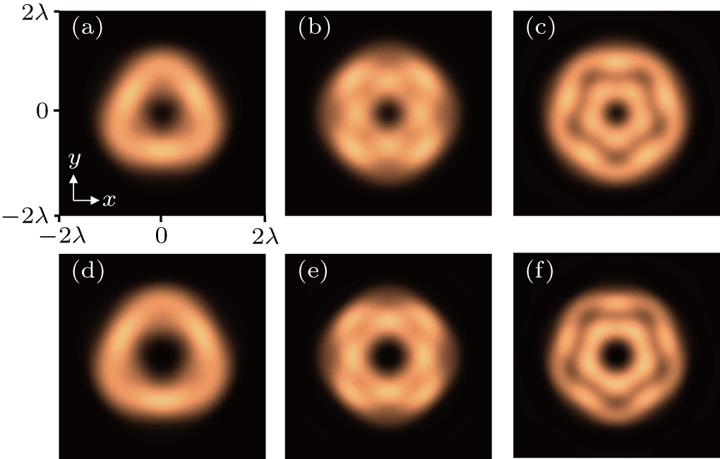
To illustrate the profile of the focused beam, the parameters used in the calculation are fixed as follows: , λ =1064 nm, NA=0.95, n0 =1.33, , f=2w0, and the laser power is 100 mW. Figure 1 shows the numerical results of the normalized intensity distribution on the X–Y plane at the focal point when m = 2, n = 3; m = 2, n = 4; m = 2, n = 5; m = 3, n = 4; m = 3, n = 5; and m = 3, n = 6, respectively. From Fig. 1, we can see that the intensity distribution is related to the difference between m and n, i.e., the intensity patterns are alternately dark and bright with q-fold rotational symmetry, where q = n−m+2. It is obvious that the topological structure of the hybrid vector beam can be transferred from the polarized state to an observable intensity pattern.
Fig. 1. Normalized intensity distribution on X–Y plane at the focal point: (a) m = 2, n = 3; (b) m = 2, n = 4; (c) m = 2, n = 5; (d) m = 3, n = 4; (e) m = 3, n = 5; (f) m = 3, n = 6. m and n are the orders of the beams used.
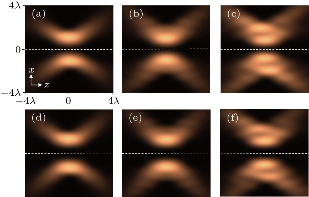
To explore the intensity profile along the propagation direction, we consider the longitudinal profile of the total intensity. Figure 2 illustrates the numerical results on the X–Z plane around the focal point, which indicates that the radial component always has zero amplitude on the z-axis.
Fig. 2. Normalized intensity distribution on X–Z plane around the focal point: (a) m = 2, n = 3; (b) m = 2, n = 4; (c) m = 2, n = 5; (d) m = 3, n = 4; (e) m = 3, n = 5; (f) m = 3, n = 6. m and n are the orders of the beams used.
When we calculate the intensity distribution with λ =532 nm, we obtain the similar intensity patterns as those in Figs. 1 and 2. Although the wavelength affects the size of the focal field and the magnitude of the focal intensity, the pattern of the focal intensity is independent of the wavelength. Therefore, we can conclude that such an intensity distribution is a characteristic of the focused hybrid vector beam. As is known, the intensity distribution affects the optical force, which results in new phenomena. Hence, it is natural to apply such interesting intensity distributions on small absorbing Rayleigh particles to investigate the resulting mechanical effects.
3. Optical force of a tightly focused hybrid vector beam
For absorbing Rayleigh metallic particles, one can use the dipole approximation to calculate the radiation force. The timed-averaged optical force on Rayleigh particles is given by[29,30]
where ε0 is the permittivity of vacuum, ε is the relative permittivity, and a is the radius of a spherical particle, which is much smaller than the wavelength λ. From Eq. (9), the optical force can be divided into two parts. The first term is known as the gradient force , and is proportional to the gradient of intensity. The second term can be easily identified as the radiation pressure , which is proportional to the real part of the Poynting vector. By substituting Eqs. (6)–(8) in Eq. (10), we can obtain the components of the optical force analytically. In this paper, we consider absorbing gold particles with radius 50 nm ( at 1064 nm, at 532 nm)[32] in the calculation.
3.1. Trapping by transverse optical force
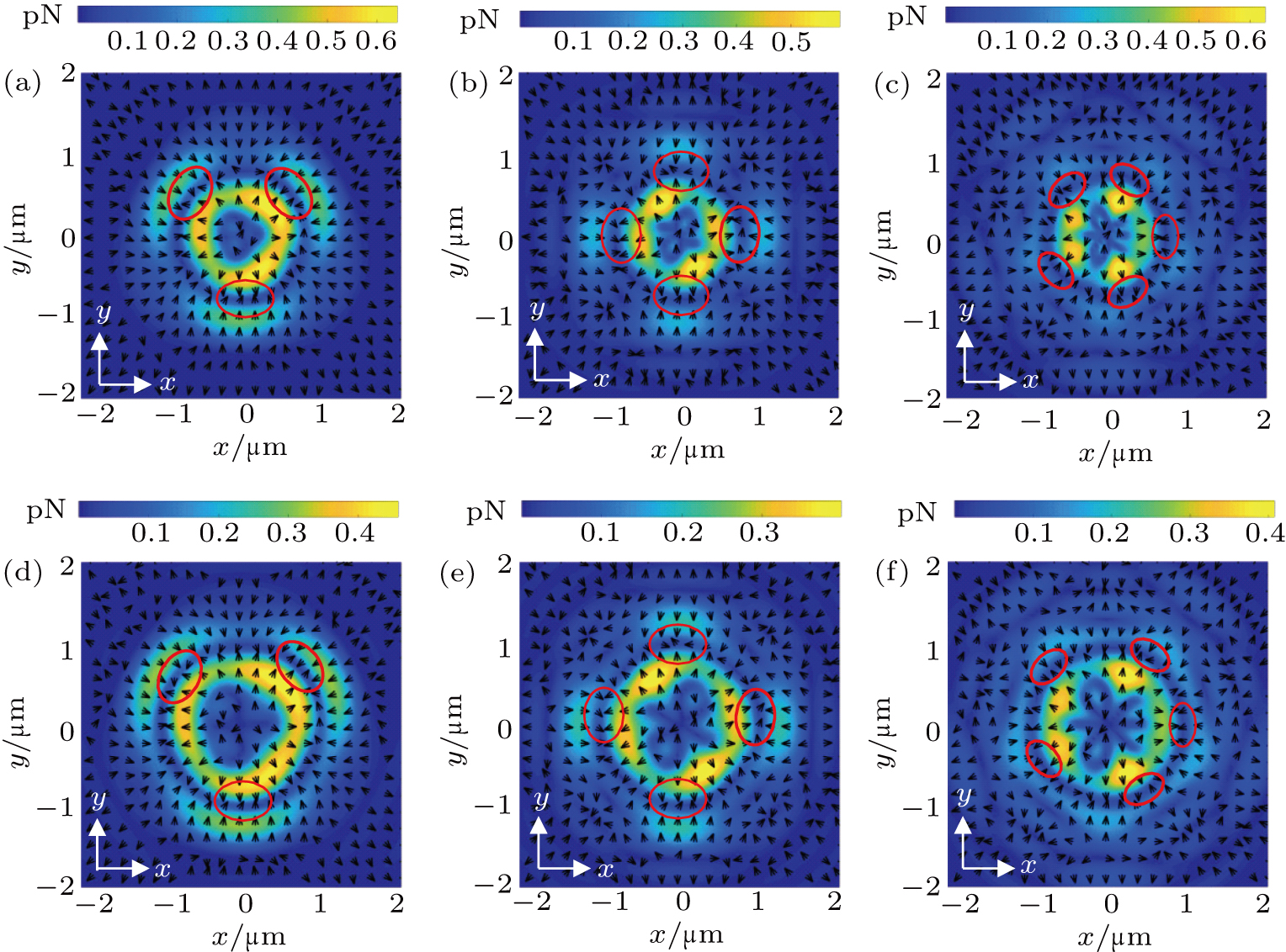
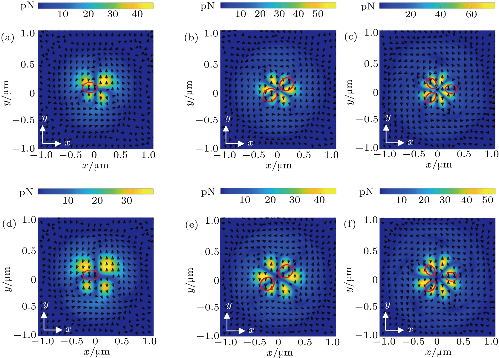
First, we consider the particles to be confined in the X–Y plane. We use the optical parameters mentioned in Section 2, with λ = 1064 nm, and also adopt the cases of m = 2, n = 3; m = 2, n = 4; m = 2, n = 5; m = 3, n = 4; m = 3, n = 5; and m = 3, n = 6, respectively, to illustrate the transverse optical forces. The magnitude and direction distributions of the transverse force are shown in Fig. 3. We can find that the trapping of particles is mainly determined by the difference between n and m. Specifically, in the case of m = 2, n = 3 or m = 3, n = 4, the transverse trapping force is mainly concentrated in the three regions marked by the red circles in Figs. 3(a) and 3(d), which implies that particles could be confined in these sites. In the case of m = 2, n = 4 or m = 3, n = 5, the particles would be trapped in four petal-like regions (Figs. 3(b) and 3(e)). As for m = 2, n = 5 or m = 3, n = 6, the particles would be confined in five petal-like regions (Figs. 3(c) and 3(f)). It can be concluded that the number of trapping positions is equal to n−m=2, which corresponds to the q-fold rotational symmetry of the intensity pattern. In any case, the metallic Rayleigh particles could be confined in multiple regions, i.e., multiple trapping could be realized.
Fig. 3. Magnitude and direction distributions of the transverse force for 1064 nm: (a) m = 2, n = 3; (b) m = 2, n = 4; (c) m = 2, n = 5; (d) m = 3, n = 4; (e) m = 3, n = 5; (f) m = 3, n = 6. The red circles denote the trapping positions. m and n are the orders of the beams used.
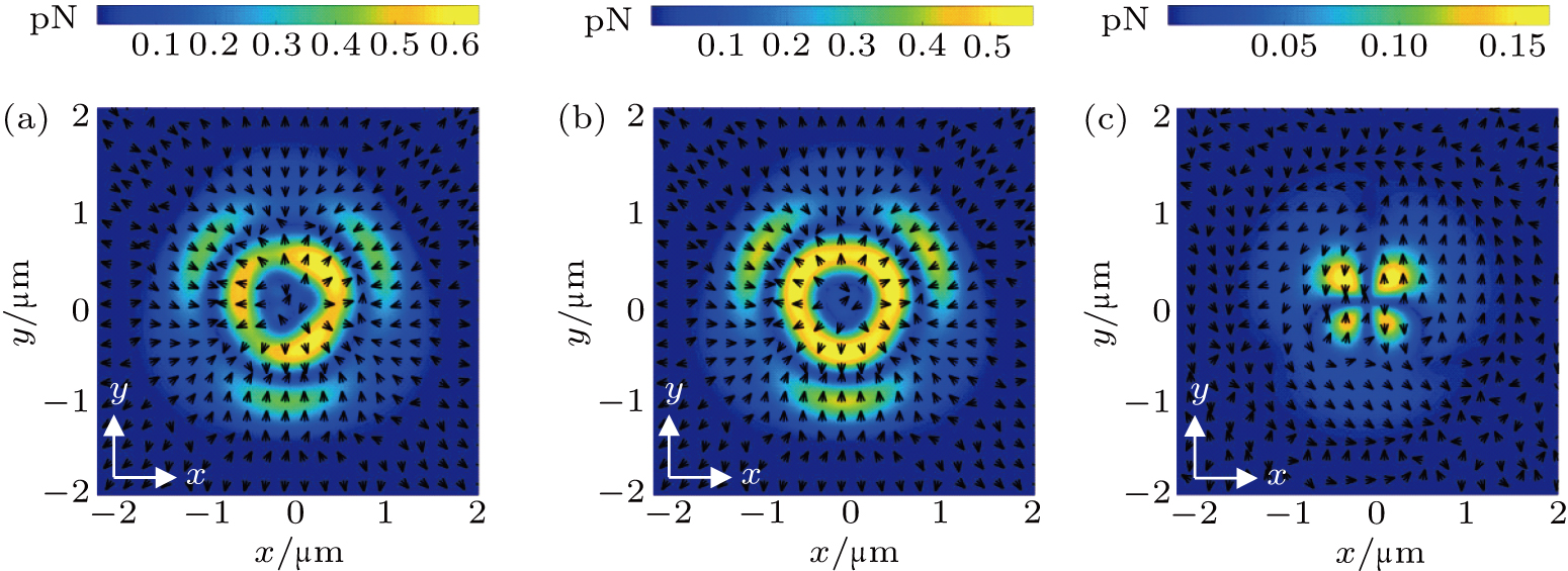
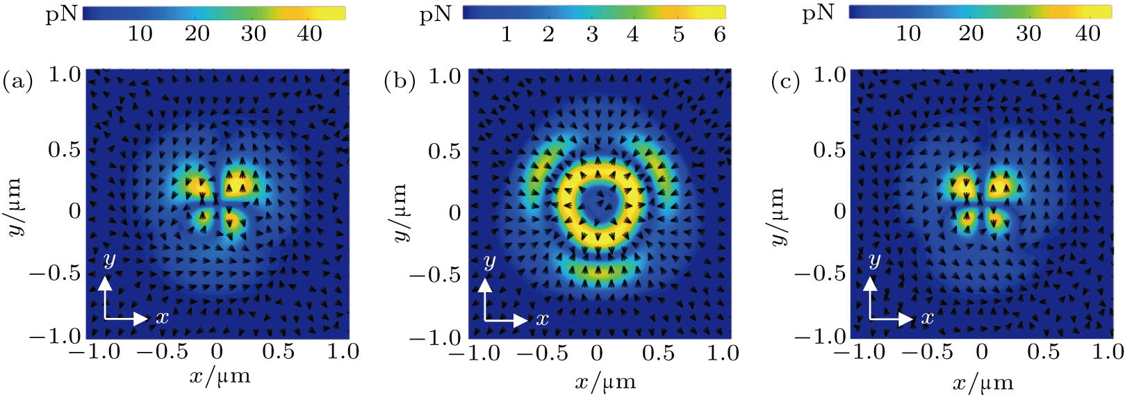
Taking the case of m = 2, n = 3 as an example, we illustrate the transverse force and its components in Fig. 4. We find that the magnitude of the gradient force is much larger than that of the scattering force (see the color bars in Fig. 4). The gradient force is mainly determined by the intensity distribution, whereas the scattering force has little relation with the intensity distribution. Therefore, the total optical force with λ = 1064 nm relies on the intensity pattern. It is observed that the case of m = 2, n = 3 exhibits a three-fold rotational symmetry for both the force distribution (see Fig. 3(a)) and the intensity pattern (see Fig. 1(a)). This is also true for the other cases, e.g., the cases of m = 2, n = 4 and m = 3, n = 5 exhibit a four-fold rotational symmetry; the cases of m = 2, n = 5 and m = 3, n = 6 exhibit a five-fold rotational symmetry.
Fig. 4. Components of the transverse force when m = 2, n = 3 for 1064 nm. (a) Total force, (b) gradient force, (c) scattering force. m and n are the orders of the beams used.
Next, we investigate the influence of the wavelength on the optical force. We replace the wavelength of 1064 nm by 532 nm, which results in relative permittivity changing. Without loss of generality, we leave other parameters unchanged, and recalculate the transverse force, as shown in Fig. 5. This figure manifests a force distribution that is quite different from that of λ = 1064 nm in Fig. 3. However, the mechanism of particle trapping is still determined by the difference between n and m. In the case of m = 2, n = 3 or m = 3, n = 4, the particles are confined in one region alone, which is located in the negative x-axis (Figs. 5(a) and 5(c)). In the case of m = 2, n = 4 or m = 3, n = 5, the optical force traps the particles in two regions in a diagonal direction (Figs. 5(b) and 5(e)). In the case of m = 2, n = 5 or m = 3, n = 6, the particles are trapped in three regions. Therefore, it is clear that multiple trapping could be realized in the case of 532 nm also. However, unlike for the wavelength of 1064 nm, the number of trapping positions is equal to n − m.
Fig. 5. Magnitude and direction distributions of the transverse force for 532 nm: (a) m = 2, n = 3; (b) m = 2, n = 4; (c) m = 2, n = 5; (d) m = 3, n = 4; (e) m = 3, n = 5; (f) m = 3, n = 6. The red circled regions mark the trapping positions. m and n are the orders of the beams used.
To find the reason for the difference in the optical force for wavelengths of 1064 nm and 532 nm, we present the force components in the case of m = 2, n = 3 for the wavelength of 532 nm in Fig. 6. Even though the direction of each force component is similar to that for λ = 1064 nm, the total force is quite different, because the scattering force is comparable to, or even greater than, the gradient force (see the color bars in Fig. 6). From Eqs. (10) and (11), it can be seen that the gradient force is mainly determined by the real part of permittivity, while the scattering force relies on the imaginary part of permittivity. In the case of λ = 1064 nm, because the real part of permittivity is much larger than the imaginary part, the contribution of the gradient force dominates. However, for the case of λ = 532 nm, as the imaginary part is comparable to the real part, the contributions of the scattering force could not be neglected. The change in the wavelength changes the real and imaginary parts of permittivity, and hence, the total force exhibits different magnitude and direction distributions. This phenomenon can provide a basis for combining optical forces at different wavelengths to explore richer application scenarios in multiple trapping.
Fig. 6. Components of the transverse force in the case of m = 2, n = 3 for 532 nm. (a) Total force, (b) gradient force, (c) scattering force. m and n are the orders of the beams used.
3.2. Trapping in three-dimensional space
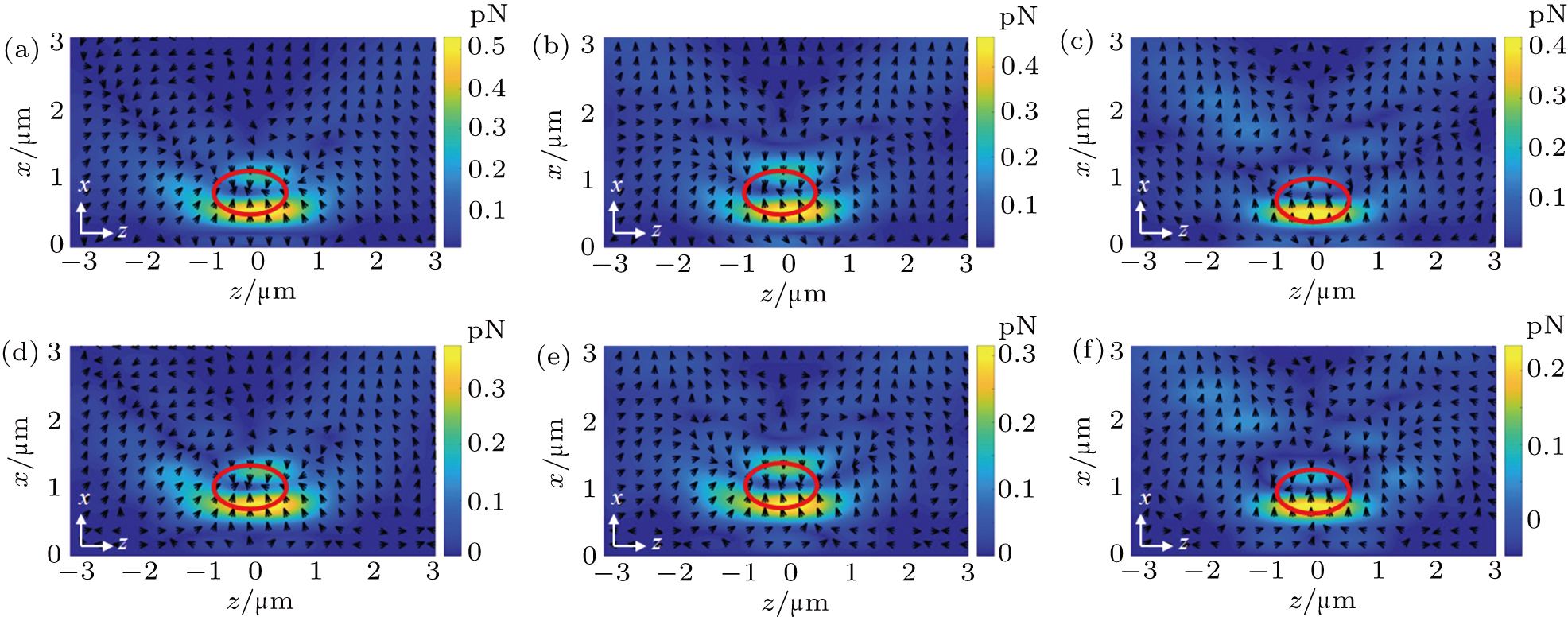
To explore the possibility of multiple tapping in three-dimensional space, we consider the contribution of the longitudinal force. Based on the optical parameters mentioned in Section 2, we plot the force distribution on the X–Z plane, as shown in Figs. 7 and 8. For the wavelength of 1064 nm (see Fig. 7), all the cases show similar longitudinal force distributions, which can be interpreted using the intensity distribution shown in Fig. 2. It is clearly seen that all particles can be gathered around the focal plane. Therefore, in three-dimensional trapping, at the position where the transverse plane is stably captured, stable capture in the longitudinal direction can be established by the longitudinal optical force. Meanwhile, we should stress that the transverse force plays a key role in confining and organizing particles, while the longitudinal optical force shows little effect on distributing particles.
Fig. 7. Force distribution on X–Z plane for the cases of 1064 nm: (a) m = 2, n = 3; (b) m = 2, n = 4; (c) m = 2, n = 5; (d) m = 3, n = 4; (e) m = 3, n = 5; (f) m = 3, n = 6. The red circles denote the trapping positions. m and n are the orders of the beams used.
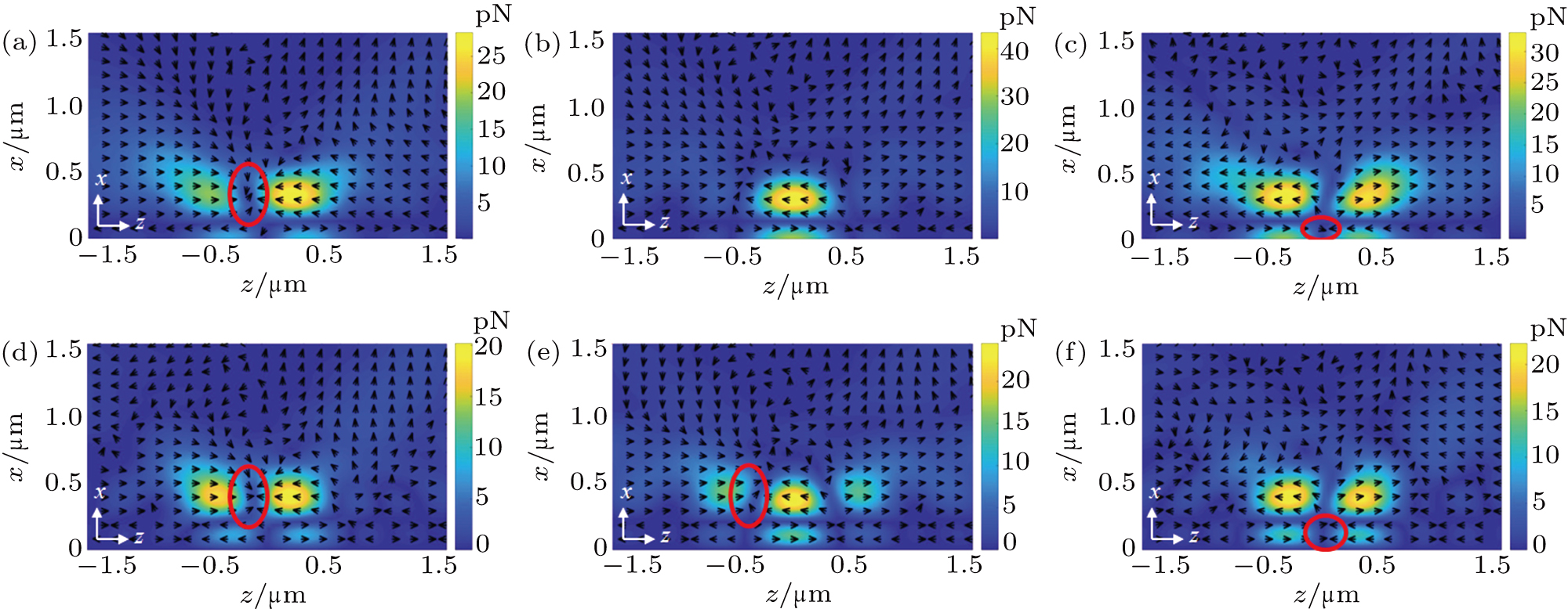
For the case of 532 nm, the scattering force can not be neglected, so the longitudinal optical force shows different trapping positions from the case of 1064 nm. Combining Fig. 5 with Fig. 8, it can be observed that the longitudinal optical force drags the particles to the vicinity of the focal plane instead of the focal plane, and then, the transverse force distributes the particles to multiple sites. That is, three-dimensional multiple trapping can also be established. Specifically, the capture locations of the longitudinal force are determined by the topological charges m and n. For m = 2, n = 3 (Fig. 8(a)), m = 3, n = 4 (Fig. 8(d)), or m = 3, n = 5 (Fig. 8(e)), the particles are pulled near the z-axis. For m = 2, n = 5 (Fig. 8(c)) or m = 3, n = 6 (Fig. 8(f)), the particles are dragged to the z-axis. It is worth to note that the case of m = 2, n = 4 could hardly trap particles (Fig. 8(b)), because one of the opposite directional forces is so small that it performs a unidirectional force along the z direction.
Fig. 8. Force distribution on X–Z plane for the cases of 532 nm: (a) m = 2, n = 3; (b) m = 2, n = 4; (c) m = 2, n = 5; (d) m = 3, n = 4; (e) m = 3, n = 5; (f) m = 3, n = 6. The red circles denote the trapping positions. m and n are the orders of the beams used.
Finally, we estimate the trapping stability to verify if the optical trapping could overcome the kinetic energy of the Brownian motion of particles. A classically accepted criterion is , where , α is predefined in Eq. (11), Emax is the maximum filed on particles, T is the environment temperature, and kB is the Boltzmann constant. At T = 300 K, the values of Rthermal for the previous cases are found to be less than 10−32. Therefore, Brownian motion could be suppressed in our case, and the Rayleigh particles could be trapped stably.
4. Conclusion
In summary, we employed a tightly focused hybrid vector beam to realize multiple trapping. By numerically analyzing the transverse force and its components, we revealed the mechanism of multiple trapping. A point of particular interest is that the positions and number of optical trapping sites could be controlled by the wavelength and topological charges m and n of the input beam. Furthermore, we found that multiple trapping could be extended to three-dimensional space if we considered the contribution of the longitudinal force. Our method makes particles organization simpler and more controllable. We expect our work to enrich the perspective on the interaction between laser beams and particles, and provide further effective applications in the fields of nanoparticle and living biological cell manipulation. In the future, we will explore structure fields further to achieve multiple trapping by a single beam.


